STUDY ON THE PROPERTIES OF PARTS MANUFACTURED USING FUSED DEPOSITION MODELING (FDM)
ANWAR NAIMI BIN ARSAT
i
SUPERVISOR DECLARATION
“I hereby declare that I have read this thesis and in my opinion this thesis is sufficient in terms of scope and quality for the award of the degree of
Bachelor of Mechanical Engineering (Design and Innovation)”
Signature: ………
FUSED DEPOSITION MODELING (FDM)
Anwar Naimi Bin Arsat
This thesis is submitted as
partial fulfillment of the requirement for the award of Bachelor of Mechanical Engineering (Design & Innovation)
Faculty of Mechanical Engineering Universiti Teknikal Malaysia Melaka
iii
DECLARATION
“I declare this thesis is on my own work except for summary and quotes that I have mentioned its sources”
Signature: ………..
Name of Author: Anwar Naimi Bin Arsat
v
ACKNOWLEDGEMENT
First thing first, I would like to express my gratefulness to the great Creator, Allah S.W.T. on completing this undergraduate project successfully.
Apart from the efforts of me, other acquaintances are giving so much encouragement and supports on completing this undergraduate project. I wish to express my sincere appreciation to my helpful supervisor, Ir. Dr. Mohd Rizal bin Alkahari from Faculty of Mechanical Engineering, for all the tremendous supports, guides, and motivations. Without his support, this thesis will never been better than this. My millions thank also goes for both my beloved parents; Salmah bte Mohamed and Arsat bin Samsudin. Thank you so much for the endless support that they have given me and this thesis will be nothing without their blessings.
Last but not least, the group of people who willingly sacrifice their own quality time for the sake of true friendships, my colleagues and housemate, Muhammad Afdhal bin Nazan, Muhammad Syazwi bin Mohd Faudzee, and Nur Irsyad bin Mohamad Thani for helping and guiding me and contributing on giving quality ideas.
ABSTRACT
vii
ABSTRAK
Tujuan penyelidikan ini adalah untuk mengenal pasti kualiti komponen yang dihasilkan dengan menggunakan kaedah model pengendapan terlakur (FDM). FDM ialah salah satu teknik yang digunakan dalam pembangunan prototaip dengan menggunakan pendekatan fabrikasi tambahan. Mesin FDM yang digunakan dalam eksperimen ini adalah mesin pencetak 3D Mini Kossel dan mesin pencetak Cube Pro. Proses parameter adalah kepadatan cetakan, corak cetakan , pilihan luaran, sudut raster, ketebalan lapisan dan jarak corak. Eksperimen memberi tumpuan lebih kepada jarak corak kerana kedua-dua mesin FDM mempunyai ketersediaan untuk mengubah suai parameter ini. Kualiti bahagian-bahagian yang dihasilkan telah dicapai dari segi kekasaran permukaan, kekuatan tegangan dan keliangan. Kekasaran permukaan, kekuatan tegangan dan data keliangan masing-masing diperolehi dengan menggunakan Roughness Tester TR200, mesin Instron Floor Mounted dan Inverted Microscope. Keputusan menunjukkan kenaikan parameter jarak corak akan menurunkan kekuatan tegangan. Jarak corak juga mempengaruhi nilai keliangan dan kekasaran spesimen ujian.
TABLE OF CONTENT
CHAPTER TITLE PAGE
SUPERVISOR DECLARATION i
DECLARATION iii
DEDICATION iv
ACKNOWLEDGEMENT v
ABSTRACT vi
TABLE OF CONTENT viii
LIST OF TABLES xi
LIST OF FIGURES xii
LIST OF ABBREVATIONS xiv
LIST OF APPENDICES xv
1 INTRODUCTION 1
1.1 Background 1
1.2 Problem Statement 2
1.3 Objectives 2
ix
CHAPTER TITLE PAGE
2 LITERATURE REVIEW 3
2.1 Introduction 3
2.2 Fused Deposition Modeling 4
2.3
2.2.1 Acrylonitrile-Butadiene-Styrene (ABS) 5
2.4 Experimental Design Process 6
2.5 Process Parameters 7
2.5.1 Build orientation 8
2.4. 2.5.2 Tool path generation 9
2.6 Mechanical Properties of Material 11
2.7 Experiment Setup 13
3 METHODOLOGY 14
3.1 Introduction 14
3.2 Sample Preparation 14
3.3 Slic3r Software 16
3.2.1 3.3.1 STL preparation 24
3.4 FDM 3D printer 25
3.4.1 Mini Kossel 3D printer 26
3.4.2 Cube Pro 3D printer 32
3.5 Surface Roughness 33
3.6 Porosity Test 34
3.7 Tensile Test 36
3.8 Test Specimens 37
4 RESULTS & DISCUSSIONS 38
4.1 Tensile Test 38
4.1.1 Tensile Data 40
4.1.2 Tensile Result 41
4.2 Surface Roughness Test 43
4.3 Porosity Test 44
5.2 RECOMMENDATIONS 50
REFERENCES 51
xi
LIST OF TABLES
TABLE TITLE PAGE
2.1 FDM parameters and their level 10
2.2 Moduli and strength of material 12
2.3 Some mechanical properties with different orientation 13
3.1 Specimen dimension for thickness 15
3.2 The description of geometry function Interface 19 3.3 The description of color, build, print and help interface 20
3.4 The description for figure 3.9 and 3.1.1 21
3.5 The description for setting tab and printer configuration 22
3.6 Build setting interface 23
3.7 FDM machine comparison 26
3.8 All parts of Mini Kossel 3D printer 26
4.1 Tensile strength data 40
4.2 Elastic modulus data 41
4.3 Average roughness data 43
4.4 Porosity data 45
LIST OF FIGURES
FIGURE TITLE PAGE
2.1 Fused deposition modeling process 4
2.2 ABS polymer and its functionality 5
2.3 Effects of FDM parameters on tensile and flexural strength of test specimen
8
2.4 Build direction of specimen for tensile test (X, Y and Z). 9
2.5 Parameter of tool path 10
2.6 Test specimens and dimensions (ASTM D 638) 13
3.1 Dimension drawing based on types 15
3.2 Sample specimen is design by using CAD software 16
3.3 Build direction for the specimens 17
3.4 Slic3r software interface 17
3.5 Interface tabs 18
3.6 CAD files function 19
3.7 Geometry functions 19
3.8 Color, build, print and help 20
3.9 Zoom and view 21
3.1.1 Prints paths 21
3.1.2 Setting tab & printer configuration 22
3.1.3 Build setting 23
3.1.4 Test specimen is prepare from Cube Pro software 24
xiii
3.1.6 Cube Pro 3D printer 32
3.1.7 Inside view of Cube Pro 3D printer 32
3.1.8 Example of measurement of surface roughness 33
3.1.9 Arrow indicate pat of roughness measured 33
3.2 Inverted microscope 34
3.2.1 Image J interface 34
3.2.2 Digital weight balance and graduated cylnder 35 3.2.3 INSTRON floor mounted and clamped specimen 36
3.2.4 Bluehill software 37
3.2.5 Test specimen printed by both FDM machine 37
4.1 Tensile Specimen after test 39
4.2 Stress-strain graph 39
4.3 Graph of tensile strength 42
4.4 Graph of young’s modulus 42
4.5 Graph bar chart of average roughness 44
4.6 Microstructure magnification 45
4.7 Original images and image measured 45
4.8 Bar chart graph of porosity 46
4.9 Effect of pattern spacing on porosity 47
LIST OF ABBREVATIONS
ABS = Acrylonitrile-Butadiene-Styrene
ASTM = American Society for Testing and Materials CAD = Computer Aided Design
FDM = Fused Deposition Modeling FEA = Finite Element Analysis PLA = Polylactic-Acid
xv
LIST OF APPENDICES
NO TITLE PAGE
CHAPTER 1
INTRODUCTION
1.1 BACKGROUND
2
1.2 PROBLEM STATEMENT
In fused deposition modeling the part’s mechanical properties depend mainly on process parameters such as the material depositing orientation, the filament flow rate, the raster's separation, raster angle, pattern spacing and the extrusion temperatures. This final year project investigates the plastic material used in FDM manufactured parts and to determine the quality of parts where the process parameter is being optimized.
1.3 OBJECTIVES
The objectives of this project are:
1. To investigate the mechanical properties of parts manufactured using FDM.
2. To study the influence of processing parameters on mechanical properties.
3. To improve the existing FDM machine and compare its influence on parts properties
1.4 SCOPE OF PROJECT
For this project, there are three scopes in order to achieve the project objectives:
1. The project study the effects of pattern spacing on mechanical properties 2. The project utilizes both Mini Kossel and Cube Pro 3D printer
mechanical properties.
CHAPTER 2
LITERATURE REVIEW
2.1 INTRODUCTION
4
2.2 FUSED DEPOSITION MODELING
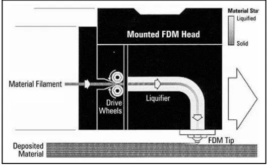
[image:21.595.183.449.302.468.2]Rapid prototyping (RP) technologies have continuously evolved over time. There are many RP technologies existed. FDM is one of the technologies used to produce prototype from plastic material. Acrylonitrile butadiene styrene (ABS) is an example of plastic filament used to make the prototype by laying path of the molten state of the filament onto a print bed layer by layer from the base to the top (Raut et al., 2014). Figure 2.1 show the process of FDM.
Figure 2.1: Fused deposition modeling process (Ahn S. H. et al., 2002)
The physical procedure of manufacture, an ABS filament is nourished through a heated component and turns to be semi-liquid. The filament is then nourished through the tip of the nozzle and stack onto the mostly built part. Since the filament is in semi- liquid state, the newly deposited material stack with adjacent material that already been extruded (Ahn S. H. et al., 2002). The FDM head then
acrylonitrile, butadiene, and styrene. They were created with the harmony of hardness and softness by improving the brittleness, which is the disadvantage of polystyrenes, through addition of a rubber component while maintaining hardness and fluidity, which are the advantages of polystyrenes. Figure 2.2 show the ABS polymer and its functionality.
Figure 2.2: ABS polymer and its functionality (Charles A. H., 2002)
6
2.4 EXPERIMENTAL DESIGN PROCESS
There are eight steps to complete an experimental design process. Each step must be follow in order to obtain the good conclusion of the experiment. The experimental design begins by determining the goal for the experiment. This is to set the objective of the experiment what leads to desired result. The goal must be straightforward and clear so that an experiment strategy can be developed. If the experiment is ended in success or failure, there is a plan of action need to be taken.
After the goal has been set, a measure of success must be defined. The feature of the process or the product must be metric and refer to an intrinsic. The critical part of meeting the goal set is by the responses of a large number of responded.
After step one and two is completed, we must make a rough estimation in order to verify the feasibility involve. By using the power of calculation, information that are gather can be determine whether any is reasonable with the number of trials. If there is larger amount of noise present in the process, the amount of trial required to see a change in the desired parameter.
The next step is to make a precise estimation of the designing the experiment. In order to conduct the experiment, the design of the experiment must be constructed. To obtain the response variable the control variable must be identified first hand.
After all the design experiment is complete with the variable involve, the experiment are conducted. The experiment is a task in resource management in order to obtain the data. The experiment must be complete as efficiently as possible in order to achieve an accurate data.
prediction from several responses.
Lastly after all steps are completed, the result produce must take action. Compare the result whether it is related with the goal set in the first step. Determine whether the experiment is a success or a failure. The experiment result of the experiment must be documentation for future use as a reference.
2.5 PROCESS PARAMETERS
There are several process parameters such as part build orientation and tool path parameters like layer thickness, pattern spacing, raster angle, raster width and air gap.In FDM, one of the critical factor is to select the buildup orientation of the model since it affects the different areas of the model like main material, support material, built up time, total cost per part and most important the mechanical properties of the part (Raut et al., 2014). The investigation done by (Jaimin et al.,