COMPARATIVE STUDY OF ENERGY-EFFICIENT FLUORESCENT LAMPS (COMPACT FLUORESCENT LAMP)
NAZRULHISHAM ZAIDAN
This Report Is Submitted In Partial Fulfillment of Requirements For The Degree Of Bachelor in Electrical Engineering (Power Electronics And Drives)
Fakulti Kejuruteraan Elektrik Universiti Teknikal Malaysia Melaka
ii
―I hereby declared that I have read through this report and found that it has comply The partial fulfillment for awarding the degree of Bachelor of Electrical Engineering
(Power Electronics and Drives).‖
Signature : ... Supervisor’s Name : EN. MD. HAIRUL NIZAM BIN TALIB
iii
―I hereby declared that this report is a result of my own work except for the excerpts that have been cited clearly in the references.‖
Signature : ... Supervisor’s Name : NAZRULHISHAM BIN ZAIDAN
iv
To Mom and Dad
Your prayers keep me moving forward Lecturers
Fill my heart with the truth and knowledge Beloved friends
Make my world happens Every Muslims
v
ACKNOWLEDGEMENT
In the name of Allah, The Most Gracious, The Most Merciful. Peace be upon the Messenger of Allah, Muhammad s.a.w, his companions (r.a) and followers until the Judgement Day. Thanks to Allah, with His blessing, this final project is successfully delivered.
In this opportunity, I would like to express my gratitude to my supervisor, Mr.Hairul Nizam B. Talib for all the guidance, ideas, support and encouragement that he gave to me during doing this project. Without his support, there will be no progression for this project.
Besides, I also would like to express my appreciation to all lecturers that help me especially along this project and my studied in Universiti Teknikal Malaysia Melaka.
vi
ABSTRAK
The comparative study of energy-efficient fluorescent lamps is to prove that the energy-efficient fluorescent lamps products in the market can save energy and money as claimed. This project will achieve by 2 sections which is hardware and software simulation.
In hardware simulation, the model of basic home lighting is designed. All the data that is needed will take using the measuring equipment such as ammeter, Fluke Quality Analyzer and oscilloscope.
In software simulation, all data will taken by using PsPise software. To do this research, 3 brands of energy-efficient fluorescent lamps is selected. The 3 brands of energy-efficient fluorescent lamps is from:
Philips
Osram
Best
vii
ABSTRACT
Projek Comparative study of energy-efficient fluorescent lamps ini dijalankan adalah untuk membuktikan sama ada dapat menjimatkan tenaga dan kewangan seperti yang didakwa oleh setiap syarikat pembuat lampu . Projek ini akan dijalankan dalam 2 bahagian iaitu simulasi dan pengambilan data menggunakan instrumen tertentu.
Dalam bahagian perkakasan, model asas pendawaian lampu di rumah akan direka dan digunakan untuk pengambilan data menggunakan intrumen tertentu seperti ammeter, Fluke Quality Analyzer dan osiloskop.
Dalam bahagian perisian, semua data akan diambil menggunakan perisian Pspice. Dalam melaksanakan penyelidikan ini, tiga jenama dari berlainan syarikat pembuat dipilih. Tiga jenis lampu yang dipilih adalah:
Philips
Osram
Best
viii
LIST OF CONTENT
CHAPTER TITLE PAGE
SUPERVISOR’S CONFORMATION
TITLE PAGE i
CONFESSION ii
DEDICATION iii
ACKNOWLEDGEMENT iv
ABSTRACT v
ABSTRAK vi
LIST OF CONTENT vii
LIST OF TABLE xii
LIST OF FIGURE xiii
LIST OF ABBREVIATION xvi
LIST OF APPENDIX xvii
I INTRODUCTION
1.1 Project Objectives 1
1.2 Project Scope 1
1.3 Problem Statements 2
1.3 Report Outline 2
II LITERATURE REVIEW
ix
Cathode Fluorescent Lamps 4
2.1.1 Theoretical Analysis Of The Preheating Process 4 2.1.2 Theoretical Analysis Of The Steady-State
Operation 6
2.2 Self Oscillating Circuit for CFL 10W 6 2.2.1 Circuit & System Description 6
2.2.1.1 Half Bridge Inverter 7
2.2.1.2 Startup Phase 7
2.2.1.3 Ignition Phase 8
2.2.1.4 Burn Phase 8
III THEORITICAL ANALYSIS
3.1 Introduction 11
3.2 Electronic Ballast Circuit 12
3.2.1 Voltage Fed Half Bridge Ballast 12 3.2.1.1 Variation on Voltage fed half bridge
circuit 13
3.2.1.2 The circuit operation 13 3.3 Benefit of using Electronic Ballast 14
3.3.1 Increased Light Output 15
3.3.2 Flicker Elimination 15
3.3.3 Audible Noise Elimination 15
3.3.4 Lower Ballast Power 16
3.3.5 Extended Lamp Life 16
3.3.6 Versatile Lamp Control 16
3.3.7 Compact And Light Weight 17
3.4 Electronic Ballast Sub-Circuit 17
3.4.1 Rectifier Circuit 18
3.4.1.1 Full-Wave Rectifier 18
x 3.4.1.3 Analysis and Calculation 22
3.4.2 Oscillator Circuit 23
3.4.3 Inverter Circuit 23
3.4.3.1 Center Tapped Half Bridge Inverter 23
3.4.3.2 Circuit Operation 24
3.4.4 Resonant Circuit 24
3.4.4.1 Series Resonant Inverter 26 3.4.4.2 Theoretical Analysis Of The Preheat
Steady-State Operation 26
IV METHODOLOGY
4.1 Planning And Management 31
4.2 Research (Hardware) 31
4.2.1 Fluke Quality Analyzer 32
4.2.1.1 Measuring Lighting Load 33 4.2.2 Hardware Setup Installation And Testing 34
4.3 Research (Simulation) 34
4.3.1 Reconstruction Circuit Design 34
4.4 Calculation Section 37
V RESULT
5.1 Introduction 38
5.2 Philip Electronic Ballast Measurement Result 38 5.2.1 Philips Rectifier Voltage And Current 38 5.2.2 Philips Inductor Voltage And Current 39 5.2.3 Philips Filament Voltage And Current 40 5.2.4 Philips Lamp Voltage And Current 41
5.2.5 Philips Frequency 43
xi 5.2.7 Philip Total Harmonic Distortion 44 5.2.8 Philips Power consumption 46
5.3 Simulation Result 48
5.3.1 Philips Input Power 48
5.3.2 Philips rectifier 49
5.3.3 Philips Resonant Circuit 50
5.3.3.1 Inductor L1 Voltage 50
5.3.3.2 Capacitor C2 Voltage 51
5.3.3.3 Inductor L1 Current 52
5.3.3.4 Capacitor C1 Voltage 53
5.3.3.5 Capacitor C1 Current 54
5.3.3.6 Voltage Across Lamp 55
5.3.3.7 Current Across Lamp 56
5.3.3.8 Lamp Inrush Current 57
5.3.3.9 Lamp Active Power 57
5.3.3.10 Total Current Harmonics Distortion 58
5.4 Calculation 60
VI ANALYSIS AND DISCUSSION
6.1 Introduction 61
6.2 Simulation Analysis 61
6.2.1 Combination Waveform 61
6.3 Measurement Analysis 64
6.3.1 The Effect of C1 Electronic Ballast 64
6.3.2 Crest Factor 65
6.3.3 Power Factor 65
6.3.4 Circuit Frequency Larger Than Resonant
Frequency 68
6.3.5 Total Harmonic Distortion 69
xii 6.4 Analysis Between Measurement, Simulation And
Calculation Result 71
6.4.1 Rectifier 72
6.4.2 Inductor Voltage 73
6.4.3 Power Consumption 73
VII CONCLUSION AND SUGGESTION
7.1 Conclusion 75
7.2 Recommendation 76
REFERENCES 78
xiii
LIST OF TABLE
NO TITLE PAGE
4.1 The Value Of All Important Component Using For Simulation 36 5.1 Simplified Result From The Hardware Measurement 47
5.2 Total Current Harmonics Distortion Data 58
5.3 Simulation Result From Three Brands 59
5.4 Calculation Result From All Three Brands 60
6.1 Relationship between THD and Power Factor and Crest Factor 66 6.2 Relationship between THD and Lamp Operating Frequency 71 6.3 Comparison between Measurement, Calculation and Simulation
Result of Output Rectifier 72
6.4 Comparison between Measurement, Calculation and Simulation
Result of Inductor 72
6.5 Comparison between Measurement, Calculation and Simulation
xiv
LIST OF FIGURE
NO TITLE PAGE
2.1 Fluorescent Lamp Model during Pre-heat Process 4
2.2 Complete Circuit During Preheat Process 5
2.3 Simplified Circuit During Preheat Process 5
2.4 Fluorescent Lamp Model during Steady-State Operation 6
2.5 Block Diagram of experiment circuit 6
2.6 Experiment Circuit 10
3.1 Series-resonant parallel-loaded half-bridge inverter 11
3.2 Voltage Fed Half Bridge Ballast 12
3.3 Variation on Voltage fed half bridge 13
3.4 Block Diagram of Electronic Ballast 18
3.5 Full Wave Rectifier Circuit and Waveform 19
3.6 Positive half-cycle rectification 19
3.7 Negative half-cycle rectification 19
3.8 AC, half-wave and full wave rectified signals 20
3.9 Buffer capacitor 20
3.10 Half Bridge Inverter 24
3.11 Series Resonant Waveform 25
3.12 Series Resonant -Peak Waveform 26
3.13 Equivalent Circuit of Electronic Ballast and Fluorescent Lamp 27
4.1 Basic Home Wiring 32
4.2 Fluke Quality Analyzer 32
xv
4.4 The Process of Reconstruction Circuit 35
4.5 Rectifier Circuit for Electronic Ballast Used in Simulation 36 4.6 Overall Circuit for Electronic Ballast Used in Simulation 36
4.7 Flow Diagram Of The Project. 37
5.1 Rectifier Voltage And Current Data Measured From Fluke Quality
Analyzer 38
5.2 Rectifier Voltage And Current Waveform Measured From Fluke
Quality Analyzer 39
5.3 Inductor Voltage and Current Data Measured From Fluke Quality
Analyzer 39
5.4 Inductor Voltage And Current Waveform Measured From Fluke Quality
Analyzer 40
5.5 Filament Voltage And Current Data Measured From Fluke Quality
Analyzer 40
5.6 Filament Voltage And Current Waveform Measured From Fluke
Quality Analyzer 41
5.7 Lamp Voltage And Current Data Measured From Fluke Quality
Analyzer. 41
5.8 Lamp Voltage Waveform Measured From Fluke Quality Analyzer 42 5.9 Lamp Current Waveform Measured From Fluke Quality Analyzer 42 5.10 Frequency for the Philip electronic ballast from the measurement. 43 5.11 Inrush Current for the Philip electronic ballast from the measurement. 43 5.12 Inrush Current Waveform Measured From Fluke Quality Analyzer 44 5.13 Philip Total Harmonic Distortion from the measurement. 44 5.14 Philip Total Current Harmonic Distortion Waveform Measured From Fluke
Quality Analyzer 45
5.15 Philip Total Harmonic Distortion Diagram Measured From Fluke Quality
Analyzer 45
5.16 Power consumption for the Philip electronic ballast from the
measurement. 46
xvi
Analyzer 46
5.18 Waveform of Philips Input Power 48
5.19 Waveform of Rectifier Output 49
5.20 Voltage across Inductor Waveform 50
5.21 Voltage across Capacitor C2 Waveform 51
5.22 Inductor Current across Waveform 52
5.23 Voltage across Capacitor C1 Waveform 53
5.24 Capacitor C1 Current Waveform 54
5.25 Voltage across Lamp Waveform 55
5.26 Lamp Current Waveform 56
5.27 Lamp Inrush Current Waveform 57
5.28 Lamp Active Power Waveform 57
5.29 Total Current Harmonics Distortion Waveform 58
6.1 PHILIPS Circuit Simulation During Preheat and Steady-State Process 63 6.2 OSRAM Circuit Simulation During Preheat and Steady-State Process 63 6.3 BEST Circuit Simulation During Preheat and Steady-State Process 64 6.4 Analysis of Crest factor for BEST electronic ballast 66 6.5 Analysis of Crest factor for PHILIPS electronic ballast 66 6.6 Analysis of Crest factor for OSRAM electronic ballast 67 6.7 Analysis of Phase Angle between Voltage and Current Supply for
BEST electronic ballast 67
6.8 Analysis of Phase Angle Between Voltage and Current Supply for
PHILIPS electronic ballast 68
6.9 Analysis of Phase Angle Between Voltage and Current Supply for
OSRAM electronic ballast 68
6.10 Line Voltage and Line Current Of Typical Electronic Ballasts 70
6.11 Simplified Circuit 70
xvii
LIST OF ABBREVIATION
DC Direct Current
AC Alternative Current
ANSI American National Standard Institute IC Integrated Circuit
xviii
LIST OF APPENDIX
NO TITLE PAGE
A Fluke Quality Analyzer Method 80
B OSRAM Measurement Result 86
C BEST Measurement Result 96
D OSRAM Simulation Result 105
E BEST Simulation Result 116
F PHILIPS Calculation Result 127
G OSRAM Calculation Result 136
H BEST Calculation Result 144
I Electronic Ballast Circuit Using Integrated Circuit 152 J Components Used In Electronic Ballast Circuit Using Integrated
xix
CHAPTER I
INTRODUCTION
Electronic ballasts for fluorescent lamps have been extensively used in lighting systems because of their advantages over conventional magnetic ballasts, namely, reduced volume and weight, higher efficiency, higher lamp efficacy (lumens per watts ratio, due to the high operating frequencies), absence of audible noise, absence of stroboscopic effect [1]
1.1 Project Objectives
a. To obtain the design, construction and operation of the energy-efficient fluorescent lamp including all electronic parts/circuits for selected brand
b. To collect the main characteristic/data of the energy-efficient fluorescent lamps such as resistor, inductor, capacitor, efficiency, starting voltage and current and luminance
c. To make the comparison between the calculation and simulation results
1.2 Project Scope
xx a. Three brands of electronic ballast circuit including:
i. Philips ii. Osram iii. Best
b. Voltage fed half bridge ballast circuit
c. 4 mains circuit of electronic ballast including:
i. Rectifier Circuit ii. Inverter Circuit iii. Resonant Circuit
1.3 Problem Statements
Manufacturers of the lamp claim that the light produce by themselves are energy saving and there are no prove that can support this theory. There is nobody that makes a research individually to support that theory. May be this is because the costumer believe that the company always did the testing and developing for that product all the time at the factory.
The costumer also think that all energy-efficient fluorescent lamps can saving their money and energy without think maybe there are an effect by using it. In fact, not all the energy-efficient fluorescent lamps can provide all the terms that is claimed.
1.4 Report Outline
xxi review of this project. This chapter reviews the related work that has been done by other people
Some theory of this project will be discussed including the electronic ballast circuit and some explanation about the circuit operation. is in chapter 3.. Chapter 5 is the main part of this report. It has four main sections which are:
a. Hardware implementation /Measurement Result b. Simulation Result
c. Calculation Result
xxii
CHAPTER II
LITERATURE REVIEW
2.1 Setting the Preheating and Steady-State Operation of Electronic Ballasts, Considering Electrodes of Hot-Cathode Fluorescent Lamps [5]
The thesis is present a new methodology of the pre-heat and steady-state operation electronic ballast by using hot-cathode fluorescent lamp. In this thesis, the circuit using is series-resonant half bridge inverter (voltage half bridge).
2.1.1 Theoretical Analysis Of The Preheating Process
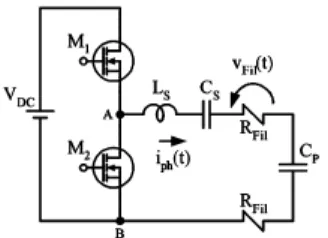
xxiii A new lamp model has been developed to represent the variation of the as a function of time, considering the injection of a current with constant rms value through the electrodes [6]. Figure 2.1 shows the graphic representation of the lamp model, during the preheating process.
During the preheating, the gas column of the lamp is considered as an open-circuit in agreement with the lamp model. Moreover, the equivalent resistances of the filaments are relatively low when compared to the total impedance of the circuit. Therefore, it is possible to neglect their values in the analysis of the circuit shown in Figure 2.1. This assumption is very important because it allows a significant simplification in the analysis of the circuit.
[image:23.612.249.413.384.503.2]According to these assumptions, the equivalent circuit of the electronic ballast and fluorescent, during the preheating, can be represented by Figure 2.2.
[image:23.612.269.385.576.653.2]xxiv
2.1.2 Theoretical Analysis Of The Steady-State Operation
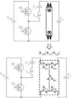
The analysis is the theoretical determination of the voltage which is applied to the lamp electrodes, during steady-state operation. Therefore, an accurate lamp model is required for the representation of the gas column, and especially the electrodes. Due to this fact, the lamp model presented based on the set of resistance shown in Figure 2.3, is considered suitable for this analysis, because it can provide good estimates of the equivalent resistances of the filament [7].
2.2Self Oscillating Circuit for CFL 10W
[image:24.612.269.391.106.273.2]2.2.1 Circuit & System Description
Figure 2.4: Fluorescent Lamp Model During Steady-State Operation
[image:24.612.123.543.604.668.2]