MODEL ANALYSIS AND LABORATORY
EXPERIMENTS OF STRENGTHENING DIAGONAL
WALL PANELS IN CONCRETE STRUCTURES
Yenny Nurchasanah
1*, Muhammad Ujianto
11
Universitas Muhammadiyah Surakarta, Engineering Faculty
A.Yani Street, Tromol Pos 1, Pabelan, Kartasura, 57102
*[email protected]
Abstract
Walls, even though being included in non-engineering building element, actually have the
strength and stiffness. In this study, the wall elements will be analyzed regarding the influence
in a system of reinforced concrete frame. The other side of this research is the adoption of
high-rising building technology in the use of shear wall elements into earthquake-safe homes.
This technology is to prevent the wall from quick collapse when exposed to seismic forces are
by strengthening the areas diagonally. Diagonal area is an area where there will be the
greatest shear force effects, and it is characterized by the appearance of cracks or even
splitting on the diagonal area. The modeling of reinforced concrete structures is applied to
SAP2000 to open frame and frame with concrete panels as filler. This is modeled as bracing
representing an area of wall. There are 37 test objects of open frame and frame with wall
concrete panels as filler (100x50x7), with diagonal reinforcement/bracing of the group of
steel reinforcing. SAP2000 analysis results indicate that the structure with wall panels have a
higher value than the capacity of open frame structure. Laboratory experimental data with
compression test showed increased values up to
215.36% on the frame with wall panel, an
increase of
271.99% on the frame wall panels with diagonal steel reinforcement. Flexural test
showed increased values up to
37.73% on the frame with wall panel and an increase of
260.76%
on the frame wall panels with diagonal steel reinforcement. The addition of diagonal
reinforcement elements is conducted to divide the force received by the wall and to increase
the strength of the wall and the stiffness of the structural system.
Keywords: concrete wall panel, compressive strength, diagonal reinforcement, flexural
strength, stiffness
Presenting Author’s biography
1.
Introduction
Earthquake improving technology.
Earthquake is one form of the natural disasters in recent years that we have seen occurring in the country. Earthquake is also considered as a devastating natural disaster that has claimed tens of thousands of lives of Indonesian society. Countless material damages incurred by natural disasters, especially earthquake, occured almost equally in the Indonesian archipelago.
Fig. 1. Construction of a brick wall in residences that collapsed in the quake
The earthquake that occurred in Yogyakarta on May 26, 2006 at a scale of 6.2 SR caused heavy damage to buildings. Dead people are mostly found inside buildings and homes made of brick construction.
Non-structural components include all components of the building that are not part of the building structure. They include the building's exterior, the interior of the building, and the building includes wall filler. The technology to prevent walls from collapsing in the event of earthquake is done through the strengthening of certain areas diagonally. Diagonal area is an area where there will be the greatest shear force effects, which are characterized by the appearance of cracks or even division on the diagonal area. The diagonal positioning of strengthening is intended to prevent cracks in the event of earthquake. When earthquake hit, causing cracks that are formed diagonally since the wall was drawn toward earthquake epicenter. If the direction of motion of fracture in the earth shakes up the wall to the front and to the rear, the diagonal reinforcement serves to hold the wall to prevent it from abrupt collapse.
Further, the flexibility of the type of material to be used as diagonal reinforcement is expected to hold the wall. Small fragments of wall material may fall when the quake hits. However, with the strengthening, it is expected that larger fraction of wall materials do not collapse abruptly. At least, those who are in the room will still have a chance to evacuate out of the room. A material used as diagonal reinforcement can be taken from the environment around the house, which is the easiest and cheapest way to obtain in their environment.
From that background, it is necessary to preliminary analysis of the behavior of reinforced concrete structures of wall panels. The research is conducted in the form of investigation of the behavior and the capacity of the frame structure with wall panels as filler modeling in SAP2000 program. Analysis of laboratory experimental regarding the compressive strength and flexural strength is done through testing of compressive strength and flexural strength wall panels in the structure of frame.
2.
Literature Review
Earthquake Resistance Building Design Philosophy
SAP2000
SAP2000 program is the development of SAP (Structure Analysis Program) made by Prof. Edward L. Wilson of the University of California at Berkeley, US around 1970. The program is able to perform the structural analysis calculations static/dynamic, during a cross-sectional design of reinforced concrete and steel structures, SAP2000 also provides a method interface that graphically simple to use the finalization of the structure analysis. Analysis and design of structures in SAP2000 begins with determining the structure of the model followed by the determination of the cross section of structural elements, design loading, analysis models, analysis of deformation of the structure, showing internal forces, and checks Voltage Elements.
Wall
Walls are vertical part of the building and serve to limit the space to another space and also serve as the recipient of the load. According to SNI 03-3430-1994, wall consists of two kinds, namely a brick wall (non-structural) and the wall structure. The brick wall is a wall made of concrete-block arrangement, which is attached to each other with mortar to form wall areas. Meanwhile, the wall structure is a wall that is planned, calculated, and used to support the weight of gravity and lateral loads.
Non-Structural Building
Non-structural components are components in buildings that do not support these components or they can be called as additional components. These components can be eliminated because they do not support the building. Non-structural components can also enhance the aesthetic value of the building. Non-structural components are divided into multiple systems, such as wall systems, floor systems, installation of water and electrical systems, doors and windows.
Concrete panels Wall
Wall panels are one of the non-structural components of a building. In general, walls are made of red bricks coated with mortar, the large volume and specific location of the buildings needs special treatment, such as in the area of the earthquake and the high rise building. The making of wall from red bricks is done in the open field, but it will have many bad impacts on the building, such as time inefficiency, wasteful labor, has its self-weight which is quite large and dangerous during an earthquake. Therefore, to overcome the shortage of red bricks walls needed to manufacture wall components, it is important to discover substitute materials that are better than the red bricks, with the replacement of precast concrete made. Since concrete has high compressive strength, weather resistance, abrasion resistant, easy maintenance and relatively cheap price, indirectly, these properties are also attached to the wall of concrete panels.
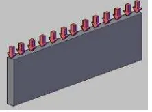
Compressive Strength Test Wall Panels
The testing the compressive strength of a wall panel is conducted by giving the load on the specimen surface to crack. According to SNI 03-4164-1996, the value of compressive strength of wall is the compressive force applied to wall pairs of each compressed sectional area of the wall.
Fig. 2. Load schemes in Compressive Strength Test Wall Panel
Flexural Strength Test Wall Panels
4165-1996, the value of flexural strength force on the wall is the wall pairs per unit sectional area of the bended wall.
Fig. 3. Load schemes in Flexural Strength Test Wall Panel
3. Research Method
Design of Mixed Concrete
The concrete mixture is composed of water, cement, fine aggregate, and coarse aggregate with maximum diameter of 10 mm. Mix design uses water-cement ratio of 0.5.
Test object Modeling
Test specimens are divided into two groups; they are the group of materials and structural components of the wall panels. Group of materials consist of 5mm x 5mm cube mortar test with 5 samples, and 5 cylinders test object ∅15cm and 30cm of height with 5 samples. As for the reinforcing steel, the researchers prepared 5 test specimens for each diameter and type of reinforcement steel. The group test of wall using a panel of wall structure with the dimensions of B x H x T is 1000x500x70mm.
Fig. 4. Configuration with a group of diagonal reinforcement steel bars
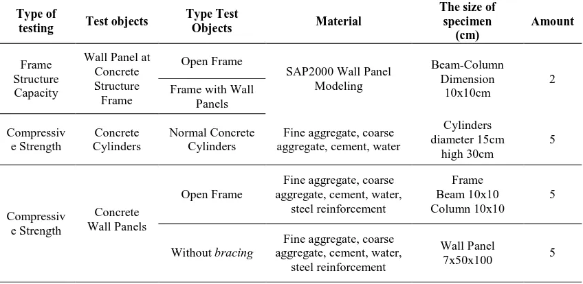
Table 1. Details of Model and Experimental Laboratory Test Objects Type of
testing Test objects
Type Test
Group of reinforcing steel bracing dp6 Steel stirrup 2dp4
Concrete cover 1cm
100
Type of
testing Test objects
Type Test
Open Frame aggregate, cement, water, Fine aggregate, coarse steel reinforcement
Structure Test Equipment Component
The test object is installed on the bottom of Loading Frame, which was previously given higher steel bearings and locking mounted on the left and right side to prevent it from moving. At the top part of the specimen, the researchers installed some bearings made of iron plate with wood on the top part, and gave lubricant between the pads. Hydraulic jack is mounted just above the specimen to provide monotonic load in one direction. To measure the magnitude of the applied load, the researchers used reading load, maximum load capacity 25 ton, which is placed between the specimen and the hydraulic jack. Tools and loading frame are adjusted to the size of the specimen.
4.
Data Analysis
SAP2000
After modeling the structure, loading calculation, and inputting the data into SAP2000 program, the data will be obtained through internal forces on the beams and columns that have been modeled. Internal forces data are used to design flexural beam and column design capacity. Based on the analysis in SAP2000 structure, a structure with a wall has better ductility value and capacity base shear is higher than the open frame structure. The structure with wall has better behavior compared to the open frame structure. Stiffness and strength of the wall influence the reinforced concrete structure.
Wall Panels Compressive Strength
Table 2. Wall Panels Compressive Strength
Wall Panels Flexural Strength
As presented in Table 3, it is known that the average of flexural strength of open frame wall panels at 0.660 MPa, while the average of flexural strength without the diagonal wall panels is at 0.909 MPa; showing an increase of 37.73%. The average of flexural strength of wall panel with a diagonal reinforcement is 2.381 MPa; showing an increase of 260.76% from the open frame wall panels, and increased bending strength of 161.94% of the average flexural strength without reinforcement diagonal wall panels reinforcing steel.
Table 3. Wall Panels Flexural Strength
No Type Wall Panel
The results of the modeling analysis panel walls with diagonal reinforcement of reinforced concrete structures with SAP2000 show changes in the value of a higher capacity compared to the structure without diagonal reinforcement. Laboratory experimental evaluation shows that there is an increase in the value of the capacity of the wall panels with diagonal steel reinforcement compared to wall panels without diagonal reinforcement. Diagonal reinforcement material may improve the brittle cracks of the wall and the destruction becomes more ductile. An increase in the compressive strength and flexural strength in the wall due to the reinforcement of the diagonal area of the test specimen is added to the reinforcement which contributes to the strength of the structure.
References
[1] ACI Committee 318. Building Code Requirements for Reinforced Concrete (ACI 318-02). American Concrete Institut, Detroit, 2002.
[2] ASTM. Standard Test Methods forCyclic (Reversed) Load Test for Shear Resistance of Walls for
Buildings. Designation: Vol 405, E 2126 – 02a, 2003.
[3] FEMA 306. Evaluation of Earthquake Damaged Concrete and Masonry Wall Buildings, Basic
Procedures Manual. 555 Twin Dolphin Drive, Suite 550 Redwood City, California, 1998.
[5] Y. Nurchasanah. Force Distribution in the main bars of Reinforced Concrete Coupling Beams
with Diagonal Reinforcement. Jurnal EcoRekayasa, Pasca Sarjana - UMS, Vol. 3, N0. 2, 2007. [6] Y. Nurchasanah. Ductility Behavior of Reinforced Concrete Coupling Beams with Diagonal
Reinforcement Between Deform type with CRT Bar Type. Jurnal Gelagar, Fakultas Teknik –
UMS, Vol. 17 No.02, 2006.
[7] R. Park, Paulay T.. Reinforced Concrete Structure, Seventh Edition. John Willey & Sons Inc. Canada, 1975.
[8] P. T. Priestley M.J.N. 1992. Seismic Design of Reinforced Concrete Structure and Massonary
Building, Third Edition. John Willey & Sons Inc. Canada.