UNIVERSITI TEKNIKAL MALAYSIA MELAKA
EVALUATION AND SENSITIVITY ANALYSIS FOR SELECTING
THE BEST DESIGN OF AUTOMOTIVE FENDER USING ANALYTIC
HIERARCHY PROCESS (AHP)
By
MUHAMMAD ASYRAF BIN ABDUL JALIL
B051110244
900731045549
FACULTY OF MANUFACTURING ENGINEERING
UNIVERSITI TEKNIKAL MALAYSIA MELAKA
BORANG PENGESAHAN STATUS LAPORAN PROJEK SARJANA MUDA
TAJUK: Evaluation and sensitivity analysis for selecting the best design of
automotive fender using Analytic hierarchy process (AHP)
SESI PENGAJIAN: 2014/2015 Semester 1
Saya MUHAMMAD ASYRAF BIN ABDUL JALIL
mengaku membenarkan Laporan PSM ini disimpan di Perpustakaan Universiti Teknikal Malaysia Melaka (UTeM) dengan syarat-syarat kegunaan seperti berikut: 1. Laporan PSM adalah hak milik Universiti Teknikal Malaysia Melaka dan penulis. 2. Perpustakaan Universiti Teknikal Malaysia Melaka dibenarkan membuat salinan
untuk tujuan pengajian sahaja dengan izin penulis.
3. Perpustakaan dibenarkan membuat salinan laporan PSM ini sebagai bahan pertukaran antara institusi pengajian tinggi. atau kepentingan Malaysia sebagaimana yang termaktub dalam AKTA RAHSIA RASMI 1972)
(Mengandungi maklumat TERHAD yang telah ditentukan oleh organisasi/badan di mana penyelidikan dijalankan)
i
DECLARATION
I hereby, declared this report entitled “Evaluation and sensitivity analysis for selecting the best design of automotive fender using Analytic Hierarchy Process (AHP)” is the results of my own research expect as cited in references.
Signature : ………..
Author’s Name : ………..
APPROVAL
This report is submitted to the Faculty of Manufacturing Engineering of UTeM as a partial fulfillment of the requirements for the degree of Bachelor of Manufacturing Engineering (Manufacturing Design) ( Hons.). The member of the supervisor is as follow:
iii
ABSTRAK
Memandangkan keputusan yang tidak sesuai terhadap konsep reka bentuk di peringkat
awal pembangunan sentiasa membawa kepada penglibatan kos yang besar dan akhirnya ke
arah memacu komponen pra-matang atau kegagalan produk. Projek ini memberi
penekanan kepada keputusan serentak menggunakan Proses Hierarki Analisis (AHP) pada
peringkat reka bentuk konseptual untuk membantu pereka dalam membuat keputusan yang
betul dalam proses pembangunan produk. Pembangunan fender automotif telah dipilih
sebagai kajian kes untuk menggambarkan Proses Analisis Hierarki (AHP) kaedah adalah
cara terbaik dalam pemilihan konsep reka bentuk yang terbaik. Selain itu, pilihan Expert
Choice akan digunakan untuk penilaian dan analisis sensitiviti konsep reka bentuk. Selain
itu, pilihan perisian Expert Choice 11.5 digunakan untuk penilaian dan analisis sensitiviti
konsep reka bentuk. Untuk menunjukkan rangka kerja pemilihan konsep reka bentuk yang
dicadangkan itu, lima konsep reka bentuk yang berbeza telah dipertimbangkan. Keputusan
menunjukkan bahawa Design Concept 5, DC5 dengan peratusan keutamaan tertinggi
28.5% adalah reka bentuk fender automotif terbaik berbanding dengan konsep reka bentuk
yang lain. Penilaian terakhir konsep reka bentuk yang diperolehi dengan melakukan 4
senario analisis kepekaan dan analisis menunjukkan bahawa terbukti DC5 adalah reka
ABSTRACT
Considering inappropriate decisions on design concept at the early stage of development
always lead to huge cost involvement and ultimately drive towards premature component
or product failure. The project emphasize on simultaneous decision using analytical
hierarchy process (AHP) at the conceptual design stage to assist designers in making the
right decisions during the development process of products. The development of
automotive fender was chosen as a case study to depict Analytical Hierarchy Process
(AHP) method is the best way in selection the best design concept. AHP is also used to
identify the factors that influence the conceptual design. Besides that, Expert choices
software is used for evaluation and sensitivity analysis the design concept. To demonstrate
the proposed design concept selection framework, five different design concepts were
considered. The results revealed that Design Concept 5, DC5 with highest priority
percentage 28.5% is the best automotive fender design compared to other design concepts.
The final judgment of the design concept is gained by performing 4 scenarios of the
sensitivity analysis and the analysis showed that is proven DC5 is the best design for
v
2.2 Fender Process Development 7
2.3 Suitable Criteria for Automotive Fender 8
2.3.1 Safety 8
2.3.2 Performance 10
2.3.3 Stylist 11
2.3.4 Cost 12
2.3.5 Weight 13
2.4 Analytic Hierarchy Process (AHP) 13
2.5 Basic Principles of AHP 14
2.6 Substructure Analytical Hierarchy Process 15
2.7 Development a Hierarchy Model 16
2.11 Summary 21
CHAPTER 3: METHODOLOGY 22
3.1 Method of Research 22
3.2 Stage 1: Research and Finding Phase 25
3.3 Stage 2: Methodology phase 26
3.4 Stage 3: Concept Development and Analysis Phase 28
3.4.1 Finding Suitable Criteria 28
3.4.2 3D Scanning: Platinum Faro Arm 29
3.4.3 Sketching automotive fender 31
3.4.4 Analytical Hierarchy Process analysis 32
3.5 Stage 4: Result phase 34
CHAPTER 4: METHOD SELECTION PROCESS USING AHP 35
4.1 Method of Analysis Hierarchy Process 35
4.1.1 The Problem 36
4.1.2 Hierarchy Model 38
4.1.3 Pairwise comparison matrix 40
4.1.4 Perform a judgment of pairwise comparison 40
4.1.5 Synthesizing the pairwise comparison 40
4.1.6 Perform the consistency 41
4.1.7 Step 3-6 are performed for all levels in hierarchy model 44
4.1.8 Develop Overall Priority Ranking 50
4.1.9 Result of selection 52
CHAPTER 5: RESULT AND DISCUSSION 53
5.1 Results 53
5.2 Discussion 55
5.2.1 Endorsement through sensitivity analysis 55 5.2.2 Endorsement through Finite Element Analysis (FEA) 57
CHAPTER 6: CONCLUSION 59
6.1 Recommendation 60
vii
LIST OF TABLES
TABLE TITLE PAGE
Tables 2.5 Scale for pair-wise comparison 14
Tables 2.6 Advantages and disadvantages of AHP 16
Tables 2.7 Example case study use Analytical Hierarchy Process 19
Table 4.1 Automotive fender data 36
Table 4.2 Pairwise Comparison of Criteria with Respect to Overall Goal 40
Table 4.3 Synthesized Matrix for the Criteria 41
Table 4.4 Calculation to Get a New Vector 42
Table 4.5 The Consistency test for the Criteria 43
Table 4.6 Synthesized Matrix for SF Sub-Criteria 44
Table 4.7 Calculation to Get a New Vector for SF Sub-Criteria 44
Table 4.8 The Consistency test for SF Sub-Criteria 44
Table 4.9 Synthesized Matrix for P Sub-Criteria 45
Table 4.10 Calculation to Get a New Vector for P Sub-Criteria 45
Table 4.11 The Consistency test for P Sub-Criteria 45
Table 4.12 Consistency test for Alternative SF EA 46
Table 4.13 Consistency test for Alternatives SF CZ 46
Table 4.14 Consistency test for Alternatives P AR 47
Table 4.15 Consistency test for Alternatives P S 47
Table 4.16 Consistency test for Alternatives ST 48
Table 4.17 Consistency test for Alternatives C 48
Table 4.19 The Consistency test for all Alternatives 49
Table 4.20 The Consistency test for all Alternative 51
Table 4.21 Overall Priority Vectors for Sub-Criteria with Respect
to the Criteria 51
Table 4.22 Overall Priority Vector for the Alternatives with Respect
to the Criteria 52
Table 4.23 Result of Selection 52
Table 5.1 Priority percentage 53
Table 5.2 Comparison priority percentage between MS Excel
and Expert Choice 55
Table 5.3 The results obtained by simulated four scenarios 57
Table 5.4 Result Factor of Safety between existing design
ix
LIST OF FIGURES
FIGURE TITLE PAGE
Figure 2.1 example first automotive car fender with long and width design 5
Figure 2.2 Cadillac V8 Phaeton is the first car that designed sweeping
fender lines and side-mount spares spread 6
Figure 2.3 Renault Frigate one of example car using pontoon fender after
the introduction from Earl and Cadillac 6
Figure 2.4 Automotive fender manufacturing process 7
Figure 2.5 Example car momentum change 10
Figure 2.6 Change of drag coefficient of car 12
Figure 2.7 Example of hierarchy of criteria 15
Figure 2.8 An example hierarchy model for the selection of
design concept 17
Figure 3.1 Project Flow Chart 24
Figure 3.2 Research and finding flow process 25
Figure 3.3 Methodology flow process 27
Figure 3.4 Element of the PDS 29
Figure 3.5 Platinum Faro Arm equipment 30
Figure 3.6 Process flow chart of 3D scanning process 31
Figure 3.7 Sketching flow chart 32
Figure 3.8 Flowchart for AHP analysis 33
Figure 4.1 Hierarchy model for automotive fender conceptual design 39
Figure 5.2 Priority ranking calculated by Expert Choice 54
Figure 5.3 The sensitivity graph of main criteria 56
Figure 5.4 The sensitivity graph of the main criteria with respect to
the goal when score of weight is increased by 26.9% 56
xi
LIST OF ABBREVIATIONS
AHP - Analytical Hierarchy Process
AR - Aerodynamic
MCDM - Multi-Criteria Decision Making
MS - Microsoft
P - Performance
PDS - Product Design Specification
QFD - Quality Function Deployment
RI - Random Index
S - Stiffness
SF - Safety
TOPSIS - Technique for Order of Preference by Similarity to Ideal Solution
TRIZZ - Theory of Inventive Problem Solving
xiii
N The consistency test for all alternatives 79
O Overall Priority for Sub criteria with respect to
CHAPTER 1
INTRODUCTION
The design methods generated by academia have potential to ensure efficiency in team design and help to improve the designing products result (Eder, 2008). This chapter describes the general ideas of research studies which involve Analytic Hierarchy Process (AHP) method as the main decision tool that a used for evaluating and analysis the best design of automotive fender. Basically, there are four main sections in this chapter which is the project background, problem statement, the research objective and lastly is the research scope. All main sections will be detailed descriptions.
1.1 Background
2
The Analytic Hierarchy Process (AHP) method was selected as the decision making tool in order to select the best design of automotive fender. This method was developed by Thomas Saaty in 1970. AHP is a decision making system using a mathematical model. AHP supports in determining priority criteria by evaluating multiple pairwise comparisons of each criterion. Besides that, this method is a framework for making decisions on complex issues to ease and accelerate the decision-making process by solving problems into parts, organize these parts, or variables in a hierarchy, members of the numerical value of the consideration subjective importance of each variable and synthesize these considerations to create a variable that has the highest priority and act to give effect to the results of conditions (Hsiao, 2002). Thus, a research in selecting the best design for automotive fender would be discussed in this report.
1.2 Problem Statement
The best conceptual design automotive fender is important to produce quality product. The conceptual design selection in car body panel requires specification in order to fulfill the customer needs and production line requirement. It’s a difficult task to determine the most optimum decisions on conceptual design. It is because many factors much be considerate in selection process. Inaccurate decision of selection design in product may cause redesigned the product.
1.3 Objective
The primary objective of this study is to determine the best automotive fender using Analytic Hierarchy Process. The specific objectives are:
a. Identify the factors that influence the conceptual design.
b. To conduct sensitivity analysis for verify the selection process using expert choice.
1.4 Scope of project
4
CHAPTER 2
LITERATURE REVIEW
This chapter provides the preliminary reviews for the research method of fender making approach. The literature review was clarified sustainability associated this research study. The method has been selected as the decision method in an attempt to select the best design of automotive fender is Analytic Hierarchy Process (AHP). Besides that, clear explanations of automotive fender in evaluation and sensitivity criteria analysis for selecting the best design are clearly discussed throughout this chapter.
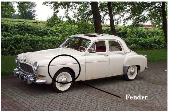
2.1 History of Automotive Fender
Figure 2.1: example first automotive car fender with long and width design (Heacock, 2014).
After that, the front and rear automotive fender and designed following to frame line. This design became preferred style for more formal cars in early 1900s. By the 1910s just about every car built in America and Europe had some form of fender designed following the body frame.
About in 1920s, American manufacturer had achieved a near equal level of engineering refinement and reliability in their products but the fender, running board and mudguards are separate components and all very much the same in appearance. According to Harley Earl, if the front fender rearward and added a recess at the bottom, the spare tire mount can be added. So, in 1927 Harley Earl brought style sweeping fender lines and side-mount spares spread to the entire Cadillac line. Example of fender designed by Harley Earl depicts in Figure 2.2.
6
Figure 2.2: Cadillac V8 Phaeton is the first car that designed sweeping fender lines and side-mount spares spread (Heacock, 2014).
About in 1933s, Earl and Cadillac introducing the pontoon fender with the original fender has been redesigned it skirted fender. Pontoon fender is the ultimately the precursor of modern automotive styling. Pontoon fender are designed more width and uninterrupted length of a car. From this design, the developer car can reduce the weight of the car. Figure 2.3 depicts the example of Pontoon fender.
Figure 2.3: Renault Frigate one of example car using pontoon fender after the introduction from Earl and Cadillac (Heacock, 2014).
Fender
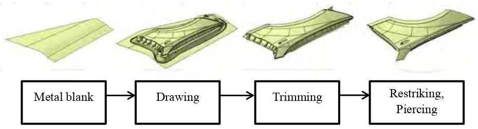
2.2 Fender Process Development
Usually automotive fender made up from sheet metal. There are four main manufacturing process of automotive fender. Figure 2.4 shows the steps of automotive fender manufacturing process.
Figure 2.4: Automotive fender manufacturing process (You et al., 2011)
The first operation in automotive fender manufacturing is drawing. The metal blank is drawn without wrinkles or cracks. The second operation is trimming. The sheet metal cut into fitting size and shape with using trimming mold. The most essential factor in this operation is trim cutter and scrap cutter position in a combination that empowers sheet metal scrap to consequently drop and be removed after trimming. In third operation, the sheet metal is formed into a desired shape also known as restriking. This activity refers to folding at any angle and is normally determined by a cam for wide areas. The last operation is piercing. When restriking had done, the position of a hole can move or gap shape can deform during shaping (You et al., 2011).
Metal blank Drawing Trimming Restriking,
8
2.3 Suitable Criteria for Automotive Fender
Just through from design can attract people to buy the product. It proves that the design is the most important process that should be on every product. Design presents your public image and dictates perceptions.
Most modern automotive fenders are designed aerodynamic. Today, automotive fenders are designed to be light, strong and unhurt passenger. The selection for the best design for automotive fender depends on some following factors:
2.3.1 Safety
The scale of deaths due to accidents is increasing every year, it is important to design safety in automotive fender. In order to have safe automotive fender, these are suitable sub-criteria for safety.
i. Energy absorb
Side impacts likewise require more attention in that there is significantly less crash zone for absorbing energy in the side of the cars compared to the front and rear structures (Strother et al., 1998), and will cause the cars user sit almost within the crash zone with always causes critical injuries (Wang et al., 2005).
Front cars are susceptible to collision during driving. The potential collision more present in high speed driving. In that respect, it is therefore necessary to design the absorb energy automotive fender to reduce the risk of injury to the occupants. So, automotive fender build with absorb energy is good to reduce the high impact collision.
ii. Crumple zone
Crumple zone also known as crush space is a structural feature mainly used in automobiles design. It’s designed for purpose to absorb the energy from the impact during car collision. According to a British Motor Insurance repair Research Centre study, mostly vehicle impact occurs 65% were front impacts, 25% rear impacts and 10% side impacts. It depicts that front part automotive have an important role to serve as crumple zone and enable it to absorb energy. This project more focuses on designing crumple zone in automotive fender (Raiciu, 2009).