UNIVERSITI TEKNIKAL MALAYSIA MELAKA
Manufacturing Process Selection for Automotive Bumper Fascia Using
Analytical Hierarchy Process
This report submitted in accordance with requirement of the Universiti Teknikal Malaysia Melaka (UTeM) for the Bachelor Degree of Manufacturing Engineering
(Manufacturing Design) (Hons.)
by
INTAN LIYANA BT. ISMAIL B050810132
891222-14-5750
UNIVERSITI TEKNIKAL MALAYSIA MELAKA
BORANG PENGESAHAN STATUS LAPORAN PROJEK SARJANA MUDA
TAJUK: Manufact uring Process Select ion for Aut omot ive Bumper Fascia Using Analyt ical Hierarchy Process
SESI PENGAJIAN: 2011/ 12 Semest er 2
Saya INTAN LIYANA BT. ISMAIL
mengaku membenarkan Laporan PSM ini disimpan di Perpust akaan Universit i Teknikal Malaysia Melaka (UTeM) dengan syarat -syarat kegunaan sepert i berikut :
1. Laporan PSM adalah hak milik Universit i Teknikal Malaysia Melaka dan penulis. 2. Perpust akaan Universit i Teknikal Malaysia Melaka dibenarkan membuat salinan
unt uk t uj uan pengaj ian sahaj a dengan izin penulis.
3. Perpust akaan dibenarkan membuat salinan laporan PSM ini sebagai bahan pert ukaran ant ara inst it usi pengaj ian t inggi.
4. **Sila t andakan (√)
SULIT
TERHAD
TIDAK TERHAD
(Mengandungi maklumat yang berdarj ah keselamat an at au kepent ingan Malaysiasebagaimana yang t ermakt ub dalam AKTA RAHSIA RASMI 1972)
(Mengandungi maklumat TERHAD yang t elah dit ent ukan oleh organisasi/ badan di mana penyelidikan dij alankan)
Int an liyana bt . Ismail
DECLARATION
I hereby, declared this report entitled “PSM Title” is the results of my own research except as cited in references.
Signature : ……….
Author’s Name : INTAN LIYANA BT. ISMAIL
APPROVAL
This report is submitted to the Faculty of Manufacturing Engineering of UTeM as a partial fulfillment of the requirements for the degree of Bachelor of Manufacturing Engineering (Manufacturing Design) (Hons.). The member of the supervisory is as follow:
i
ABSTRACT
ii
ABSTRAK
Projek ini menerangkan pendekatan, berdasarkan proses hierarki analisis (AHP) yang membantu pembuat keputusan atau jurutera pembuatan yang menentukan proses pembuatan yang paling sesuai untuk diambil bekerja dalam sektor perkilangan bumper fasia pada peringkat awal proses pembangunan produk. Masalah dalam pemilihan proses pembuatan juga telah dianggap sebagai keputusan untuk kepelbagaian kriteria disebabkan pelbagai faktor yang mempengaruhi proses pemilihan mesti dipertimbangkan. Salah satu alat kejuruteraan serentak yang boleh dilaksanakan bagi membantu jurutera pengeluaran yang menentukan proses pengeluaran yang paling optimum adalah proses analisis hierarki (AHP). Terdapat 5 jenis proses yang sedang dipertimbangkan iaitu injection moulding (IM), vacuum thermoforming, reactioninjection moulding (RIM), compression moulding(CM), dan blow moulding
(BM).5 jenis proses dipilih untuk mencari yang paling sesuai digunakan dalam
pembuatan bumper fasia yang berasaskan pada 6 pemilihan faktor-faktor utama dan 12 subfactors. Untuk menentukan proses pembuatan yang betul ianya dilakukan berdasarkan konsep AHP melalui 9 langkah. Keputusan menunjukkan bahawa proses vacuum forming adalah proses yang paling sesuai berbanding yang lain kerana ia
iii
DEDICATION
iv
ACKNOWLEDGEMENT
v
LIST OF ABBREVIATIONS, SYMBOLS AND NOMENCLATURE ix
CHAPTER 1: INTRODUCTION 1
1.1 Background of Project 1
1.2 Problem Statement 2
1.3 Objective 3
1.4 Scopes of Project 3
CHAPTER 2: LITERATURE REVIEW 4
2.1 Automotive Bumper 4
2.1.1 Bumper Systems and Components 5
2.1.2 Bumper Fascia 6
2.2 Manufacturing Processes of Bumper Fascia 7
2.2.1 Injection Moulding (IM) 7
2.2.2 Compression Moulding (CM) 8
2.2.3 Reaction Injection Moulding (RIM) 8
2.2.4 Vacuum Forming (VF) 9
2.2.5 Blow Moulding (BM) 9
2.3 Total Design 9
2.3.1 Product Design Core 10
2.4 Analytical Hierarchy Process (AHP) 15
2.4.1 Strengths and Weakness 16
2.4.2 Application 17
2.5 MindDecider Software 17
vi
CHAPTER 3: METHODOLOGY 19
3.1 Introduction 19
3.2 Project Planning 19
3.3 Flow Chart of Project 21
3.4 Conceptual Design Stage 22
3.5 Selection Process Using Analytical Hierarchy Process (AHP) 23
CHAPTER 4: ANALYSIS 24
4.1 Analytical Hierarchy Process (AHP) Methodology 24
4.1.1 Step 1: Define the problem 24
4.1.2 Step 2: Develop a hierarchical framework 25 4.1.3 Step 3: Construct set of pairwise comparison matrix 27 4.1.4 Step 4: Perform judgement of pairwise comparison 27 4.1.5 Step 5: Synthesizing the pairwise comparison 30 4.1.6 Step 6: Perform the consistency analysis 32 4.1.7 Step 7: Step (3-6) are performed for all level in the hierarchy 36 4.1.8 Step 8: Develop overall priority ranking 39 4.1.9 Step 9: Select the best alternative 42
CHAPTER 5: RESULT AND DISCUSSION 43
5.1 Result 43
5.2 Discussion 44
CHAPTER 6: CONCLUSION AND RECOMMENDATION 46
vii
LIST OF TABLES
Table 2.1 The dimensions of the Perodua Viva bumper fascia 12 Table 2.2 Strengths and Weakness of AHP 16
Table 4.1 Candidates of manufacturing process 24 Table 4.2 Scale for pair-wise comparisons 28 Table 4.3 Data used to perform pairwise comparison for the
alternatives 29
Table 4.4 Pairwise comparison of criteria with respect to overall goal 30 Table 4.5 Synthesized matrix for the criteria 32 Table 4.6 Calculation to get new vector 33 Table 4.7 Random index of analytic hierarchy process 35 Table 4.8 The consistency test for the criteria 35 Table 4.9 The consistency test for the sub-criteria (Geometry of Design) 36 Table 4.10 The consistency test for the sub-criteria (Production
Characteristics) 36
Table 4.11 The consistency test for the sub-criteria (Cost Considerations) 37 Table 4.12 The consistency test for the alternatives 38 Table 4.13 All priority vectors for criteria, sub-criteria and alternative 40 Table 4.14 Overall priority vectors for sub-criteria with respect to the
criteria 41
Table 4.15 Overall priority vector for the alternatives with resp ect to the
criteria 41
Table 4.16 Result of selection 42
Table 5.1 Results decision 43
viii
LIST OF FIGURES
Figure 2.1 Automotive bumper system components 5
Figure 2.2Viva’s bumper fascia 6
Figure 2.3 Product Design Core 10
Figure 3.1 Gantt chart for Final Year Project 20 Figure 3.2Flow chart for Final Year Project 21
Figure 3.3 Conceptual design stage 22
Figure 3.3Flow chart for AHP step 23
Figure 4.1 Hierarchical structure for selecting the best manufacturing
process 25
Figure 5.1 Mind Decider software results for the selection of
ix
LIST OF ABBREVIATIONS, SYMBOLS AND
NOMENCLATURE
AHP - Analytical Hierarchy Process
AV - Availability of Equipment and Labour BM - Blow Moulding
CD - Complexity of the Design CM - Compression Moulding CS - Cost Consideration EC - Equipment Cost EM - Ease of Maintenance
ERP - Enterprise Requirement Planning GD - Geometry of the Design
IM - Injection Moulding LC - Labour Cost MS Word - Microsoft Word
MT - Material
PC - Production Characteristics PQ - Production Quantity
SWOT - Strength, weakness, opportunity, threat
SZ - Size
TC - Tool Cost
x TS - Tolerance and Surface USA - United States of America VF - Vacuum Forming
WG - Weight
WT - Wall Thickness
° - Celsius
1
CHAPTER 1
INTRODUCTION
1.1 Background of Project
2
bumper fascia based on 6 main selection factors and 12 subfactors.Determining the right manufacturing process wasperformed based on AHP concept through the nine steps. There is no studied the application of AHP relatedto manufacturing process selection in product developmentprocess. Thus, the main focus of this project is to explore thepotential use of AHP in assisting manufacturing engineers toevaluate and determine the most appropriate manufacturing process for producing automotive bumper fascia atthe early stage of product development process.
1.2 Problem Statement
3
1.3 Objective
In this project, the main objective is to determine the best manufacturing process for automotive bumper fascia production. The specific objectives are as follows:
(a) To identify the factor influence the selection process for manufacture automotive bumper fascia
(b) To verify the results using MindDecider software
1.4 Scopes of Project
The scopes of this project are:
(a) Introduction of AHP, the automotive bumper fascia, and the conceptual design concept
(b) The criteria selection of bumper fascia. (c) The manual steps of the AHP method.
(d) The analysis of AHP method for the bumper fascia selection.
4
CHAPTER 2
LITERATURE REVIEW
2.1 Automotive Bumper
According to Helps (2001a), the main function of a bumper is to protect the car’s body in a collision. There is some difference between American and European practice in assessing performance. In North America, impact requirements for the bumper beam tend to be stringent, but damage to the fascia is not considered in meeting the requirements. Designers usually meet these specifications by making the beam stiff and having the fascia fill a purely decorative role. In Europe, impact requirements are generally less stringent but fascia damage indicates failure of the test. Therefore, the fascia plays a more structural role and material selection is more critical. However, North American car makers are showing signs of moving in the direction of European practice, especially on vehicles in which bumper system are taking on a more active energy management role. The initial move away from metal to plastic front and rear bumper on cars and related vehicles came in the USA, where bumper design is now a key styling feature. European manufacturers have followed suit.
5 2.1.1 Bumper Systems and Components
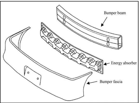
Based on Figure 2.1, the front bumper systems are consisting of fascia, energy absorber and reinforcing bumper beam. For assembling, the energy absorber is positioned between fascia and reinforcing bumper beam. The fascia envelopes energy absorber and reinforcing bumper beam in the assembled form. Means are desirable provided to fixedly attach the energy absorber to the bumper beam such as bolts and nuts. Fascia is maybe formed from a thermoplastic material which, preferably, has a finished surface and may be amenable to finishing utilizing conventional vehicle painting and/or coating techniques. As stated, generally, the fascia will envelop both the energy absorber and reinforcing bumper beam such that neither of thecomponentsis visible once they are attached to the vehicle. The fascia may be attached to the bumper beam or other part of the vehicle.
6 2.1.2 Bumper Fascia
Bumper fascia for each car is normally different in design and material.
2.1.2.1Design of Bumper Fascia
An automobile bumper fascia is a component, which contributes to vehicle crashworthiness during frontor rear collisions. According to Suddin et al. (2004), to
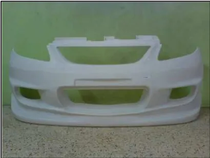
reduce air resistance when the car is moving, the bumper fascia has a ′′C′′ profile as the aerodynamic design for the fascia. The thickness of the bumper fascia is based on the idealthickness of the fascia of most passenger cars.The bumper fascia was determined with a smoothouter surface. By using the bolts and nuts, the bumper fascia needs to mount to the bumper bracket. Figure 2.2 shows the bumper fascia for Viva’s car model.
Figure 2.2: Viva’s bumper fascia
2.1.2.2Material of Bumper Fascia
7
mineral reinforcement to impact higher stiffness. Bumper fascias are considered to be a market where reactor-made TPOs are likely to have a promising future. An ultra-thin wall grade of reactor made TPO is being used in the bumper fascia of Ford’s 2000 Sable model, offering more stiffness and toughness. This is the first instance of the commercial use of reactor-made TPOs in an ultra-thin wall, directly paintable bumper fascia for a high volume vehicle. Compared with the compounded TPO it replaces, the reactor-made TPO has lower weight, reduced cost, improved base colour and better paint adhesion.
2.2 Manufacturing Processes of Bumper Fascia
There are five candidates of manufacturing processes for bumper fascia. The candidates are injection moulding (IM), compression moulding (CM), reaction injection moulding (RIM), vacuum forming (VF), and blow moulding (BM).
2.2.1 Injection Moulding (IM)
8 2.2.2 Compression Moulding (CM)
Compression moulding can be used to process both thermoplastics and thermosets, although its use with the latter material but it is not all common. This is because, with the thermoplastics, the mould would need to be alternatively heated, to shape the materials, and cooled top permit ejection from the mould cross linking materials, on the other hand, may be ejected at the high mould temperature. The major advantages of compression moulding are that it is a simple process with a little waste and particularly suitable for material that cross-link during processing. By the nature of process there are no parts where prematurely cured material can get trapped and cause prolonged down-time. Basically the system consists of matched male and female dies which are heated to temperatures between 125°-200°C. A pre-weighed charge of the material to be moulded
is placed between the two mould halves and these are then closed. Under the heat and pressure, the polymeric material plasticises, flows to the shape of the mould and become cured (Swift and Booker, 2003a).
2.2.3 Reaction Injection Moulding (RIM)
9 2.2.4 Vacuum Forming (VF)
Thermoforming processes all involve forcing a heat-softened sheet of material into or over a mold, then allowing it to cool and assume the mould shape. The mould shape for this complex thermoformed part is cooled internally to speed production. In vacuum forming, the plastic sheet is clamped and heated. A vacuum is then applied beneath the sheet, causing the atmospheric pressure to draw the sheet down against the cavity of the mold. When the plastic touch the wall of the moulds, it cools. Vacuum forming is the most widely used of the thermoforming processes. It can be used effectively even for fairly large product such as bumper fascia (DuVall, 1996c).
2.2.5 Blow Moulding (BM)
Blow moulding offers the advantage of manufacturing moulded parts economically, in unlimited quantities, with little or virtually no finishing required. It is principally mass production method. The surfaces of the moulding are as smooth and bright, or as grained and engraved, as the surfaces of the mould cavity in which they were processed. The biggest application area is for all types of bottles, but products range from small phials to large tank and bumper fascia is possible (Swift and Booker, 2003b).
2.3 Total Design
10
systematic activity necessary, from the identification of the market/user need, to the selling of the successful product to satisfy the need that encompasses product, process, people and organization.
2.3.1 Product Design Core
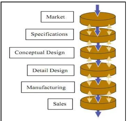
As stated by Torres (2001b), total design may be constructed as having a central core of activities, all of which are imperative for any design, irrespective of the domain. It can be called as a product design core and consist of core as shown in Figure 2.3.
Figure 2.3: Product Design Core (Torres, 2001c)
2.3.1.1Conceptual design