UNIVERSITI TEKNIKAL MALAYSIA MELAKA
AN AUTOMATIC BOTTLING PROCESS SYSTEM FOR
MONITORING AND CONTROL
This report submitted in accordance with requirement of the Universiti Teknikal Malaysia Melaka (UTeM) for the Bachelor Degree of Engineering Technology
(Industrial Power) (Hons.)
by
MUHAMAD FAIDHI ZAKWAN BIN ZANAL ARIFIN B071210009
900707-08-5049
UNIVERSITI TEKNIKAL MALAYSIA MELAKA
BORANG PENGESAHAN STATUS LAPORAN PROJEK SARJANA MUDA
TAJUK: AUTOMATIC BOTTLING PROCESS SYSTEM FOR MONITORING AND CONTROL
SESI PENGAJIAN: 2015/16 Semester 2
Saya MUHAMAD FAIDHI ZAKWAN BIN ZANAL ARIFIN
mengaku membenarkan Laporan PSM ini disimpan di Perpustakaan Universiti Teknikal Malaysia Melaka (UTeM) dengan syarat-syarat kegunaan seperti berikut:
1. Laporan PSM adalah hak milik Universiti Teknikal Malaysia Melaka dan penulis. 2. Perpustakaan Universiti Teknikal Malaysia Melaka dibenarkan membuat salinan
untuk tujuan pengajian sahaja dengan izin penulis.
3. Perpustakaan dibenarkan membuat salinan laporan PSM ini sebagai bahan
SULIT
TERHAD
TIDAK TERHAD
(Mengandungi maklumat yang berdarjah keselamatan atau kepentingan Malaysia sebagaimana yang termaktub dalam AKTA RAHSIA RASMI 1972)
(Mengandungi maklumat TERHAD yang telah ditentukan oleh organisasi/badan di mana penyelidikan dijalankan)
(TANDATANGAN PENULIS)
Alamat Tetap:
341 Lorong Taman Long Jaafar
iii
DECLARATION
I hereby, declared this report entitled “Automatic Bottling Process System for Monitoring
and Control” is the results of my own research except as cited in references.
Signature : ………
Name : ………
iv
APPROVAL
This report is submitted to the Faculty of Engineering Technology of UTeM as a partial fulfillment of the requirements for the degree of Bachelor of Engineering Technology (Electrical Technology Department) (Hons.). The member of the supervisory is as follow:
v
ABSTRACT
vi
ABSTRAK
vii
DEDICATIONS
viii
ACKNOWLEDGMENTS
First of all, I would like to thank for ALLAH for the strength and blessing until I get to here. In this project I had the opportunity to learn new skills and enhance their knowledge. I would like to congratulate Mr. Shahrudin Bin Zakaria for giving guidance and advice will never fail to make a success of this project. His guidance gives a huge role to fulfill this project.
Special thanks also I dedicate to Universiti Teknikal Malaysia Melaka for providing equipment like and information sources that assisted my studies until finish my projects. My sincere appreciation to the lecturers of Faculty Engineering Technology who put in their effort always nurtures and guides us with useful advices. Thank you for willing to share those experiences that really helps me.
ix
TABLE OF CONTENTS ... ix
LIST OF FIGURES ... xiii
LIST OF TABLE ... xiv
LIST OF SYMBOLS AND ABBREVIATIONS ... xv
CHAPTER 1 ... 1
1.0 Introduction ... 1
1.1 Background ... 1
1.2 Problem Statement ... 2
1.3 Objective Study ... 2
1.4 Scopes of Study ... 2
CHAPTER 2 ... 3
2.0 Introduction ... 3
2.1 Synopsis of Journal ... 3
x
Volume Selection ... 4
2.1.3 Implementation of Sensor Network for Automation of Bottle-Capping Assembly Station Using IEEE 802.15.4 ... 5
2.1.4 Application of PLC for Arranging Bottle in Beer Filling Production Line... 5
2.1.5 Temperature Controlling Design Based on VB and PLC... 5
2.1.6 Automatic Multivariate Liquid Filling System & Conveyor Control Using PLC & SCADA ... 6
2.1.7 Conveyor control and sorting module controlled by programmable logic controller ... 7
2.1.8 The Principle of Programmable Logic Controller and its role in Automation.7 2.1.9 GUI Based Remote ON/OFF Control and Monitoring Single Phase Lamp Using Microcontroller ... 8
2.1.10 Development of Monitoring System by Serial Port Based on VB Software and electronic Communication ... 8
CHAPTER 3 ... 10
3.0 Introduction ... 10
3.1 Project Flow ... 10
3.2 Block diagram of the project... 12
3.3 Hardware Development ... 13
3.3.1 Conveyor system ... 13
3.3.2 Power window motor ... 14
3.3.3 Programmable Logic Controller (PLC) ... 14
3.3.4 Power Supply ... 15
xi
3.3.6 Inductive Proximity Sensor ... 16
3.3.7 Pump System ... 17
3.3.8 Actuator ... 18
3.3.9 Communication port ... 18
3.3.9.1 RS232 Serial cable ... 19
3.4 Software Development ... 19
3.4.1 Programming Using Visual Basic ... 20
3.4.2 CX-Programmer ... 21
3.4.2.1 Ladder Logic ... 22
3.4.2.2 OR Operation ... 22
3.4.2.3 AND Operation ... 23
3.4.2.4 NOT Operation ... 23
CHAPTER 4 ... 25
4.0 Introduction ... 25
4.1 The Software Development ... 25
4.1.1 Design of Visual Basic ... 25
4.1.2 Source Code ... 27
4.1.3 MSComm Setting in visual basic ... 27
4.1.4 Design of Ladder Diagram ... 28
4.1.5 CX-Programmer Setting ... 29
4.1.6 Overall System ... 30
4.2 Hardware Development ... 30
xii
4.3.1 PC to PLC GUI Communication ... 31
4.3.2 ULN2803 circuit ... 32
4.4 Data time analysis ... 33
CHAPTER 5 ... 35
5.0 Introduction ... 35
5.1 Summary of Project ... 35
5.1.1 Summary of Project ... 35
5.1.1.1 Summary of Project ... 35
5.2 Achievement of Objectives ... 36
5.3 Problems Faced During Implementing Project ... 36
5.4 Discussion ... 36
5.5 Suggestion for Future Work ... 37
APPENDIX A ... 39
APPENDIX B ... 40
xiii
LIST OF FIGURES
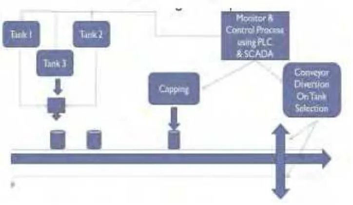
Figure 2.1: Block Diagram of the Process ... 6
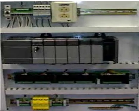
Figure 2.2: Control Panel with PLC(grey element in the centre). ... 7
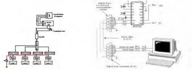
Figure 2.3: Hardware development GUI and Connection with Max232 with computer ... 8
Figure 3.1: Flowchart to Implement the Project ... 11
Figure 3.2: Block Diagram of the Project ... 12
Figure 3.3: Conveyor System ... 13
Figure 3.4: Power Window ... 14
Figure 3.5: PLC CP1E ... 15
Figure 3.6: Power Supply ... 15
Figure 3.7: Mechanical relay ... 16
Figure 3.8: Inductive Proximity Sensor ... 17
Figure 3.9: Aquarium Pump ... 17
Figure 3.10: CD-ROM ... 18
Figure 3.11: RS232c with RS232 made ... 19
Figure 3.12: Visual Basic 6 ... 20
Figure 3.13: Code Form ... 20
Figure 3.14: Graphic section form ... 21
Figure 3.15: CX-Programmer Software ... 21
Figure 3.16: Relay circuit ... 22
Figure 3.17: Ladder Logic circuit ... 22
Figure 3.18: Relay circuit ... 23
Figure 3.19: PLC Ladder logic circuit ... 23
Figure 3.20: Relay Circuit ... 24
Figure 3.21: Ladder Logic ... 24
Figure 4.1: FCS Calculation Coding ... 27
Figure 4.2:MSComm Setting ... 27
Figure 4.3: CX-Programmer comm setting ... 29
Figure 4.4: ULN2803 ... 32
Figure 4.5: Complete Serial Port interfacing circuit... 32
Figure 4.6: Illustration graph on data collection... 33
Figure 4.7: Graph of average value ... 34
xiv
Table 2-1: Synopsis of Journal ... 3
Table 4-1: Description of GUI ... 25
Table 4-2: Ladder Diagram ... 28
Table 4-3: Ladder Protection and Interrupt ... 29
Table 4-4: Control Box sequence ... 30
xv
LIST OF SYMBOLS AND ABBREVIATIONS
PLC = Programmable Logic Controller
VB6 = Visual Basic 6
PC = Personal Computer
GUI = Graphical User Interface
I/O = Input or Output
1
CHAPTER 1
INTRODUCTION
1.0 Introduction
Industrial bottling process with automation become more useful and famous among industrial world reduces the need human work. Automation plays important role closed loop system. Increasingly on world economy automation plays an important role. Automation is suitable to all type of beverage. The production will cover all complete filling and packaging process.
1.1 Background
In new era of industrial, automation is important to build fast machines by human needs. Seeing from industrial phenomena is increase like competition among Industries Company. Automation is likely can be used in many sector to develop. A prototype about bottle filling system is controlled using programmable Logic Circuit (PLC) and the process is monitored while also controlled using Visual Basic (VB).
2
1.2 Problem Statement
i. Most of the filling machine in the market is not fully automatic. This machine requires human assists to operate properly.
ii. No proper monitoring when a predicted condition happens.
iii. Some workers not know with ladder diagram so cannot monitored properly iv. If something happen during process the need to go and shut down the
operation at the machine
1.3 Objective Study
The objectives of this project are:
i. To develop a user friendly system by using Visual Basic as the monitor and control on computer
ii. To design a filling bottle system controlled by PLC
iii. To design a system that can fill the bottle with liquid where the specified quantity.
1.4 Scopes of Study
This project is primarily concerned with every phase to develop an automatic liquid filling machine. For the first phase, it starts with collecting information about the project in terms of problem statement, objective and scope. Scope should explain the objective in more detail and in accordance to the concept.
Scopes of this project are:
i. Using Visual Basic coding which is easy to use as monitor and to control the operation of the bottling process.
ii. The GUI is use to monitored the process and control the operation.
iii. Design and development ladder diagram using Omron CX-Programmer software iv. Interface PLC CP1E with visual basic 6 to make simple GUI system with low cost.
3
CHAPTER 2
LITERATURE REVIEW
2.0 Introduction
This chapter discussed about the literature discourse and review of structural analysis and some components used in these projects. Research and reference is use from various source such as journals, internet and previous projects. These items are use as the key for the whole project.
2.1 Synopsis of Journal
In this part, it involve in finding information from journal, websites and textbooks.
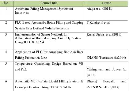
Table 2-1: Synopsis of Journal
No Journal title author
1 Automatic Filling Management System for
Industries
Ahuja et al.(2014).
2 PLC Based Automatic Bottle Filling and Capping
System User Defined Volume Selection
T.Kalaiselvi et al.
3 Implementation of Sensor Network for
Automation of Bottle-Capping Assembly Station Using IEEE 802.15.4
Kunal Utekar et al.(2011)
4 Application of PLC for Arranging Bottle in Beer
Filling Production Line ZHANG Tianxia et al.(2014)
5 Temperature Controlling Design Based on VB
and PLC Yaning sun and Junyu fu,
(2010)
6 Automatic Multivariate Liquid Filling System &
Conveyor Control Using PLC & SCADA
Dheeraj Pongallu and
4
7 Conveyor control and sorting module controlled
by programmable logic controller
G. Sujatha and V.
Perasiriyan (2014).
8 The Principle of Programmable Logic Controller
and its role in Automation.
Avaru Ravi Kiran et al(2013)
9 GUI Based Remote ON/OFF Control and
Monitoring Single Phase Lamp Using
Microcontroller
Mohd Suhaimi B.Sulaiman
et. Al.(2003).
10 Development of Monitoring System by Serial Port
Based on VB Software and electronic
Communication
Yu Tu,Chao Wang, and
Peng Du.(2011).
2.1.1 Automatic Filling Management System for Industries
Ahuja et al. (2014). This paper presents Automatic Filling Management System for industries how to control the process. A sample of bottling process control using programmable logic controller (PLC) and the process is monitored using supervisory control and data acquisition (SCADA). It will tell if there have fault occur.
2.1.2 PLC Based Automatic Bottle Filling and Capping System User Defined Volume Selection
T.Kalaiselvi et al. (2012) according to this journal, it elaborates and explains about how the flow of bottle filling involved placing bottle on the conveyor while the first bottle filling the water at the same time using old version technique . The task will involve any liquid products water even or cold drink. This task will take time and a little bit quite costly.
5
Acquisition) and being control using PLC (Programmable Logic Controllers) which is more flexible, low complexity, low cost and effective, and reduce space taken.
2.1.3 Implementation of Sensor Network for Automation of Bottle-Capping Assembly Station Using IEEE 802.15.4
Kunal Utekar et al. (2011) on his journal represented the implemented smart sensor network to improve the bottling process. The installation period had been reduced and network capacity is increase. PLC is used as a controller and microcontroller as DSDC to protect smart sensor network and available to controlling the data. Interlock Logic use to make sure all mechanical part not easily get damaged while the fault sensor is implementing from the wire break sensing concept.
2.1.4 Application of PLC for Arranging Bottle in Beer Filling Production Line
ZHANG Tianxia et al.(2014) according to his article, to an automatic and efficient production line, the subsection that being control must be optimize. During the first subsection of production lines it will arrange bottle and its need control function to make the flow of the operation smooth. PLC (Programmable Logic Controller) is installing to overcome this automatic problem control in control procedures and system architecture. Monitoring system is create to collect operation status and the design of the program, meanwhile system fault is trace and some control treatment create which to make the automatic and smooth operation of bottling arrangement. Seeing from other state the use of solenoid valve and motor are key to part as design.
2.1.5 Temperature Controlling Design Based on VB and PLC
6
temperature and upload the temperature when sensor sense. The actual temperature can be real-time display on monitor. The whole process is controlling using visual basic the programming real-time control the temperature monitoring system.
Conveniently entitles send and receive data via serial ports. MSComm is design approach to process communications event communications these process. Timely response and high reliability.
2.1.6 Automatic Multivariate Liquid Filling System & Conveyor Control Using PLC & SCADA
Dheeraj Pongallu and Prof.S.R.Suralkar(2014)Bottling plants control volume of the filling operation. In industry many PLC & SCADA system that been implemented. PLC & SCADA software interface PC to processing plants and control and monitoring between computer and hardware. Process prototype had been make using sensor, motor, relays, serial communication and PLC device. The work consists tree section, first section filling process, second conveyor process and last capping section.
Figure 2.1: Block Diagram of the Process
7
logic controller
This paper was developed by G. Sujatha and V. Perasiriyan (2014). It used PLC to investigate a conveyor sorting module controlled. In industrial conveyor plant the conveyor sorting plant module is necessary. The conveyor belt are mounted so that the object mounted on first conveyor will fall on second conveyor. It can be applied to sort the objects in depends to the size and the conveyor will stop if the sequence is wrong.
2.1.8 The Principle of Programmable Logic Controller and its role in Automation.
Avaru Ravi Kiran et al(2013).Purpose of PLC is requiring “on/off” control. There are used in many industries and device. The designation consist several input with output arrangement, PLC input and output recognize in “high” and “low” logical state. PLC read in analogue input or digital input. Then it the output generate in analogue and digital to automation system. PLC can connected in many ways to personal computer such as RS232, RS-485 or RS-422.
8
2.1.9 GUI Based Remote ON/OFF Control and Monitoring Single Phase Lamp Using Microcontroller
Mohd Suhaimi B.Sulaiman et. Al.(2003). Controller and monitoring now is an important field these days. From the electric power to the distribution grid based on automation, data acquisition and control equipment. Microcontroller is used because low cost to control hardware. Automation like control system and monitoring introduce to help people from hazardous working phenomena. This technology is efficient and more flexible.
Figure 2.3: Hardware development GUI and Connection with Max232 with computer (Source: http://www.enggjournals.com)
2.1.10 Development of Monitoring System by Serial Port Based on VB Software and electronic Communication
10
METHODOLOGY
3.0 Introduction
This chapter will discuss how the methodology works. Some aspect should be used while develop this process. This aspect will divide into several parts and important to overcome the project objective. Furthermore, the parts that consist are materials use, hardware and software relate.
3.1 Project Flow


