DESIGN OF 0.92 GHZ ARTIFICIAL MAGNETIC
CONDUCTOR FOR METAL OBJECT DETECTION IN RFID
TAG APPLICATION WITH LITTLE SENSITIVITY TO
INCIDENCE OF ANGLE
1
M. ABU, E. E. HUSSIN, A. R. OTHMAN, FAUZI. M. JOHAR, NORHIDAYAH M. YATIM,
2ROSE. F. MUNAWAR
1
Universiti Teknikal Malaysia Melaka, Faculty of Electronic and Computer Engineering 2Universiti Teknikal Malaysia Melaka, Faculty of Manufacturing
E-mail:[email protected], [email protected], [email protected], [email protected],
[email protected], [email protected]
ABSTRACT
In this paper, the new structure of Artificial Magnetic Conductor is presented. The AMC is designed to overcome the failure of detecting the RFID tag when placed near to the metal based object. It is too complicated to design an AMC at low frequency due to limitation of size and bandwidth. In this paper, the 0.92 GHz AMC is designed with different sizes and shapes of slots inserted into the square PEC patch. The size of single unit cell of this AMC is 45.5 mm x 45.5 mm. The AMC is designed in stacked layer to increase the bandwidth of single unit cell. The optimized AMC at 0.92 GHz frequency, had increase the performance of dipole antenna by return loss = -21.8 dB, gain = 3.0 4dB and directivity = 5.149.
Keywords: Artificial Magnetic Conductor, RFID, Metal object detection
1. INTRODUCTION
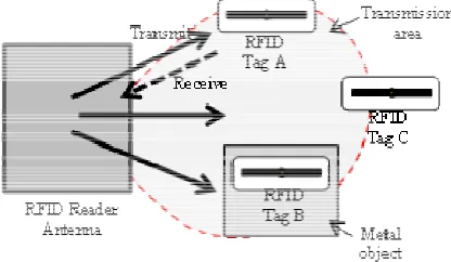
Radio Frequency Identification, RFID is not new in the world of technology today. In 1945, the idea of activating a device from outside source has been invented for military by retransmitting the radio wave into audio information. Today, the emergence of RFID technology system has makes work easier. The use of RFID can be seen in various sectors such for baggage handling, tolling system and also an anti-theft system. The basic of RFID system consists of one reader, one antenna and some piece of tags. The tag can be an active or a passive type. For passive-type tag, the size is smaller than the active-type because it has no battery attached. The communication between the reader and tag is called backscattering modulation. The reader’s antenna will transmit the electromagnetic wave into all directions. Any tag within that transmitting area will be activated by this electromagnetic wave. Then, wave will be retransmitted back to the reader. RFID system allows two-way communications between the reader and tag. Therefore, the system needs at least one device to monitor and operate the read and write process. Some add a speaker (to produce ‘beep’ sound) or LED (to emit light) to indicate
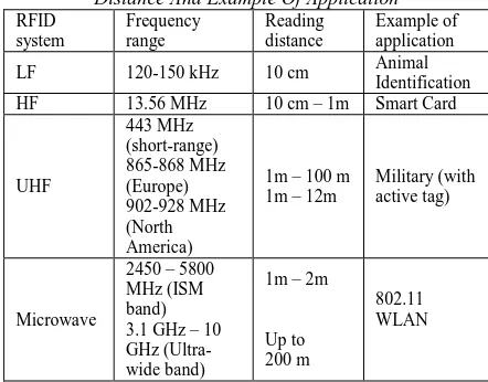
successful read and write process for each tags. The RFID system frequency operated from 120 kHz to 10 GHz. Higher frequency systems can support longer reading range but the tag size will exceedingly bigger. Table 1 shows the list of RFID frequencies and the reading distance as provided in the market.
is placed within transmission area of reader’s antenna. Therefore, the transmitting and receiving process happens. Tag B is placed outside of the transmitting area so it will stay in active. Even that Tag C in the transmitting area, the persistence of a metal plate at the back of tag had reflected all the transmitted electromagnetic wave. Therefore, Tag B and Tab C failed to operate. The problem for Tag C is due to the existence parasitic capacitance between tag and metal object. Therefore, the gain and efficiency of the tag will decrease causing total malfunction to the system. Besides, the reading distance between tag and reader also will be decrease. To overcome this problem, the tag needs to be placed at distance of quarter- wavelength apart from the metal object to reduce the suppression of surface wave. Another method is by placing the dielectric material layer at the back of the RFID tag [1-3].
Figure 1: The Communication Of RFID Tags
Artificial Magnetic Conductor, AMC is one of metamaterial structure that is designed to increase the performance of an antenna [4-6]. The use of AMC had been proved to increase the gain of the antenna by reducing the undesired back radiation and mutual coupling. In this paper, AMC will solve the problem of RFID Tag positioned on metal object. The AMC will be applied as the ground plane to redirect the radiation reflected by the metallic object. The AMC structure/design consists of AMC patch, substrate and ground layer. The AMC patch and ground layer are made by perfect electric conductor, PEC. The PEC is a material that exhibits an intrinsic electric conductivity that will reflect the incidence wave to other directions. The reflection phase of the PEC material characterized at ±180˚ while for AMC (at resonant) characterized at ±90˚ phase at free space.
Most of the RFID tag in the market is designed as dipole-type antenna. By applying AMC at the antenna ground plane may increase the gain and
reduce the backscattered / mutual coupling caused by the metal object. Result of comparison between four types of AMC in paper [7] stated that the mushroom-like EBG surface gives better bandwidth and gain performance than others AMC design when placed on a low-profile antenna at 2.45 GHz. This is due to the existence of via hole that connects the patch to the ground plane. However, this AMC structure is complex and the fabrication process is more complicated. The AMC behaves as in-phase reflection between the incidence and reflected electric field. The artificial term in AMC is used instead of the Perfect Magnetic Conductor because PMC is not exists in nature. However, AMC satisfy the physical character of PMC at certain frequency band [8].
In this paper, the AMC will be designed at low frequency 0.92 GHz by using Rogers R03010 design to reduce the dimension of the AMC but the bandwidth is reduced. In [10], two types of miniaturized AMC proposed with increased bandwidth value. Yet, the structure is very complex.
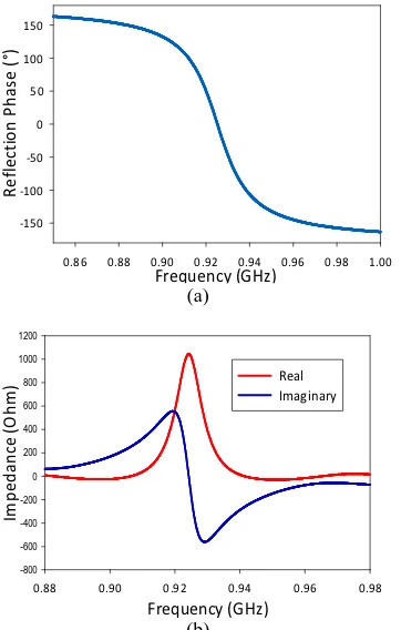
and thickness = 1.28 mm. From the simulation result of single cell AMC in Figure 2(a), the reflection phase falls on 0.9147 GHz and 0.9366 GHz at 90° and -90° respectively. Figure 2(b) shows the real and imaginary impedance of AMC. AMC is expected to have very high real impedance at resonance.
Frequency (GHz)
0.86 0.88 0.90 0.92 0.94 0.96 0.98 1.00
R
0.88 0.90 0.92 0.94 0.96 0.98
Im
Figure 2: (A) Design Structure (B) Reflection Phase And (C) Surface Impedance Of Square AMC
3. STACKED WAFER AMC AT 0.92 GHz
In this part, new AMC structure is designed to reduce the dimension of the basic square AMC. By applying slots into the first layer of PEC patch can helps to reduce the resonant frequency of AMC. Thus, the new structure will be designed with multiple slots with different size and shapes. Figure 3 shows the process of adding slots into the new design. The final structure is illustrates as in Figure 3(e). Firstly, slots with 1 mm x 2 mm is inserted and arranged in Figure 3(a). For the structure in Figure 3(a), three different sizes of slots are presented. The spacing between each slot is same for each square side. The reflection phase graph in Figure 4 shows that by applying different size of reduced from 0.93 to 0.88 (3.78%). Step three, one horizontal rectangular slot with dimension of 2 mm x 7 mm is inserted to each side of the AMC as in Figure 3(c). The decrement of frequency is about 0.96%. Next, four ‘plus’ shaped slot is inserted as in Figure 3(d). Now, it causes additional reduction of frequency to 1.64%. For the last step, one slot will be inserted to the center of AMC. Two types of slots will be discussed. First, for the square slot in Figure 3(e), the frequency decrement is very small (0.22%). Plus it causes more bandwidth reduction to 12.05%. For ‘plus’ shaped slot in Figure 3(f), it give more frequency decrement to 2.54%. Figure 4(c) shows the graph of square and plus shaped slot applied to the center of AMC. Through the shape modification in Figure 3, the bandwidth had reduced from 2.25% to 1.86%. In order to increase the bandwidth, some modification will be made to the thickness of the AMC.
(a) (b) (c)
(d) (e) (f)
as in Figure 5(b). Now the bandwidth increases to 2.04%. For the structure in Figure 5(c), 2 layer of AMC is stacked on the ground plane. The thickness is increase to 2.665 mm. Calculated bandwidth for stacked layer AMC is increased to 3.86%. Figure 6 shows the simulation result for thickness modification illustrated in Figure 5.
Frequency (GHz)
0.86 0.88 0.90 0.92 0.94 0.96 0.98
R
0.80 0.82 0.84 0.86 0.88 0.90 0.92 0.94 0.96 0.98
R
0.76 0.78 0.80 0.82 0.84 0.86 0.88 0.90 0.92
R
Figure 4: Reflection Phase Of Wafer AMC With (A) Different Of Slots Size (B) Addition Slot As In Figure
3(A) And (B), (C) Square And Plus Shaped Slot
Figure 5: Thickness Modification (A) Single Layer, (B) Substrate With Double Thickness (C) Stacked Layer
Frequency (GHz)
0.86 0.88 0.90 0.92 0.94 0.96 0.98 1.00
R
Figure 6: Thickness modification of AMC
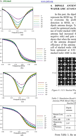
3. ANGLE OF INCIDENT
Frequency (GHz)
0.88 0.90 0.92 0.94 0.96 0.98
R
0.88 0.90 0.92 0.94 0.96
M
0.88 0.90 0.92 0.94 0.96
R
Figure 7: (A) Magnitude And (B) Reflection Phase Of Square AMC (C) Magnitude And (B) Reflection Phase Of
Stacked Wafer AMC.
4. DIPOLE ANTENNA AND STACKED
WAFER AMC AT 0.92 GHz
In this part, the dipole antenna will be used to represent the RFID tag. The purpose of this paper is to overcome the problem of metallic object detection in RFID, so it required non-complex dipole antenna design. Table 3 shows the detailed result for optimized stacked AMC at 0.92 GHz. The use of wafer stacked AMC to the back of the dipole antenna had increased the return loss value (in negative side) and gain of the antenna. The table shows that when the metal plate is applied, the gain of the antenna dropped to -13.60 dB and the efficiency of the antenna become poor. The single cell of stacked wafer AMC designed in part 3 has been optimized at 0.92 GHz. The structure of stacked wafer AMC is shown in Figure 8.
Figure 8: 3 X 1 Stacked Wafer AMC Optimized At 0.92 Ghz
Table 2: Simulation Result For Dipole Antenna, Dipole Antenna With Metal Object And Dipole Antenna With
antenna, it not just overcomes the problem cause by the metal object, but it also increase the performance of the antenna itself.
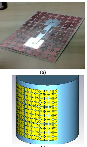
The prototype of the wafer stacked AMC is shown in Figure 9. The fabrication process is very simple and not requires higher cost. Using the RFID reader from the market, the reading distance of the AMC is measured. First, the distance for RFID is measured and the highest distance for RFID tag is measured at 5 meters. Then, the metal plate is placed at the back of the RFID tag. The RFID reader produces no sound even that the tag is placed very near to the reader’s antenna. When, the stacked AMC is placed between the RFID tag and metal plate, the longest reading distance is measured at 2.5 meters.
(a)
(b)
Figure 9: The Prototype Of Wafer Stacked AMC Applied To RFID Tag On (A) Flat And (B) Curve Surface
5. CONCLUSION
For the conclusion, the use of AMC is proved to provide shielding to the antenna from the metal object. In this paper, the new structure of wafer stacked AMC has been proposed for RFID application at 0.92 GHz frequency. The substrate used in this paper is a bendable type so it can be applied to limited bending curve surface.
ACKNOWLEDGEMENT
The authors wish to thank the Centre for Research and Innovation Management (CRIM) of Universiti Teknikal Malaysia Melaka (UTeM) for the support of this work under the grant number of PJP/2012/ FKEKK (27B) S01030.
REFRENCES:
[1]. D. Yan, Q. Gao and N. Yuan, “Strip-Type AMC Structure and Analysis to Its Band-Gap Characteristics” Progress in Elecromagnetics Symposium 2005,pp. 505-509, Aug. 2005. [2]. E. Carrubba, A, Monorchio, and G. Manara
“Artificial Magnetic Surface for Circular Polarization Movemenent” Microwave and Optical Technology Letters, Vol 5, pp.1782-1786, Aug 2010.
[3]. M Elena de Cos, Yuri Alvarez and Fernando Las-HEras, “Design and Characteristics of Planar Artificial Magnetic Conductor in the RFID SHF Band” Proceeding of Forth European Conference on Antenna and Propagation 2010, pp. 1-5, Apr 2010.
[4]. Ramona Cosmina Hadarig, M. Elena de Cos, and F. Las-Heras, “UHF Dipole-AMC Combinationfor RFID Applications”, IEEE Antennas And Wireless Propagation Letters, VOL. 12, pp: 1041-1044, 20013.
[5]. Haider R. Raad, Member, IEEE, Ayman I. Abbosh, Student Member, IEEE, Hussain M. Al-Rizzo, and Daniel G. Rucker, “Flexible and Compact AMC Based Antenna for Telemedicine Applications”, IEEE Transactions On Antennas And Propagation, Vol. 61, pp: 524-531, 2013.
[6]. B. S. Cook, Student Member, IEEE, and A. Shamim, Member, IEEE, “Utilizing Wideband AMC Structures for High-Gain Inkjet-Printed Antennas on Lossy Paper Substrate”, IEEE Antennas And Wireless Propagation Letters, Vol. 12, pp: 76-79, 2013.
[8]. Y. Liu, K.M.Luk, H.C.Yin, “A RFID Tag Metal Antenna on A Compact HIS Substrate” Progress in Electromagnetic Research Letter, Vol 18, 2010, pp:pp:51-59.
[9]. S. Barbagallo, A. Monarchio and G. Manara “Small Periodicity FSS Screens with Enhanced Bandwidth Performance” Electronic Letters, Vol 42 No 7, 2006.
[10]. M. Abu, K.A. Rahim, “Single-band and Dual-band Artificial Magnetic Conductor Ground Planes for Multi-band dipole Antenna”, Radioengineering, Vol 21 No. 4, 2012, pp: 999-1006.
[11]. M. Abu, M. K. A. Rahim, “Single-band Zigzag Dipole Artificial Magnetic Conductor”, Jurnal Teknologi UTM, Penerbit Universiti Teknologi Malaysia, pp. 19-25, 2012.
[12]. M. Hosseini, A. Pirhadi, and M. Hakkak, “A Novel AMC With Little Sensitivity To The Angle Of Incidence Using 2-Layer Jerusalem Cross FSS”, Progress In Electromagnetics Research, PIER 64, pp: 43-51, 2006.
![Figure 3(a)Figure 3(b)on AMC is important to find out the AMC stability. The study in angle of incidence of plane wave In [13], the Jerusalem cross patch metallization](https://thumb-ap.123doks.com/thumbv2/123dok/510163.57852/4.612.93.292.182.639/figure-figure-important-stability-incidence-jerusalem-patch-metallization.webp)