SIMULATION OF AN ARTICULATED ROBOT ARM
MUHAMAD FAZRUL BIN MD ZAIN
UNIVERSITI TEKNIKAL MALAYSIA MELAKA
SIMULATION OF AN ARTICULATED
ROBOT ARM
Report submitted in accordance with the partial requirements of the Universiti Teknikal Malaysia Melaka for the Bachelor of Manufacturing Engineering
(Robotics and Automation) With Honors
By
MUHAMAD FAZRUL BIN MD. ZAIN
Faculty of Manufacturing Engineering
UTeM Library (Pind.1/2007)
UNIVERSITI TEKNIKAL MALAYSIA MELAKA
BORANG PENGESAHAN STATUS LAPORAN PSM
JUDUL:
Simulat ion of an art iculat ed robot arm
SESI PENGAJIAN: Semest er 2 (2007/ 2008)
Saya Muhamad Fazrul Bin Md Zain
mengaku membenarkan laporan PSM / t esis (Sarj ana/ Dokt or Falsaf ah) ini disimpan di Perpust akaan Universit i Teknikal Malaysia Melaka (UTeM) dengan syarat -syarat kegunaan sepert i berikut :
1. Laporan PSM / t esis adalah hak milik Universit i Teknikal Malaysia Melaka dan
penulis.
2. Perpust akaan Universit i Teknikal Malaysia Melaka dibenarkan membuat salinan
unt uk t uj uan pengaj ian sahaj a dengan izin penulis.
3. Perpust akaan dibenarkan membuat salinan laporan PSM / t esis ini sebagai bahan
pert ukaran ant ara inst it usi pengaj ian t inggi. 4. *Sila t andakan (√)
SULIT
TERHAD
TIDAK TERHAD
(Mengandungi maklumat yang berdarj ah keselamat an at au kepent ingan Malaysia yang t ermakt ub di dalam AKTA RAHSIA RASMI 1972)
(Mengandungi maklumat TERHAD yang t elah dit ent ukan oleh organisasi/ badan di mana penyelidikan di j alankan)
(MUHAMMAD HAFIDZ FAZLI B MD
FAUADI)
Cop Rasmi:
Tarikh: _______________________
i
DECLARATION
I hereby, declare this report entitled “Simulation of An Articulated Robot Arm” is the result of my own research except as cited in the references.
Signature : ………..
ii
APPROVAL
This report submitted to the senate of UTeM and has been accepted as partial fulfillment of the requirements for the degree of Bachelor of Manufacturing Engineering (Robotic and Automation) with Honor. The members of the supervisory committee are as follow:
………. En Muhammad Hafidz Fazli Bin Md Fauadi
iii
ABSTRACT
iv
ABSTRAK
v
ACKNOWLEDGEMENT
Alhamdulillah, praise to God, with the deepest sense of gratitude of the Almighty ALLAH who gives strength and ability to complete this project and thesis as it today.
First of all, I would like to express my unlimited gratitude to my family who has constantly been supportive throughout the project development. They have been the ones gave me strength working on this project until its completion. I am very grateful having them in my life.
I would like to express my sincere appreciation to my project supervisor, Mr. Muhammad Hafidz Fazli bin Md. Fauadi for his support, advices and guidance in finishing this project.
vi
DEDICATION
TABLE OF CONTENTS
1.2. Problem statement ………..………..4
1.3. Objectives ……….4
1.4. Scope ………...……….5
1.5. Conclusion…..……….…..5
2. LITERATURES REVIEW………6
2.1 Introduction to robots………6
2.1.1. Types of robots ………..6
2.2. Articulated robot.………..………...………..8
2.2.1. Control of the articulated robot….……….……….………...9
2.2.1.1. Non-servo controller………….…….……….…9
2.2.1.2. Servo-controller………10
2.2.2. Robot Application………….………...……….……11
2.2.3. Design Consideration………14
2.3. Integration With Computer System ………...……….15
2.3.1. Microcontroller……….………15
2.4. Programming of Robot Arm ……….……….17
2.4.1. High level programming language.………..18
2.4.2 Low-level programming language………...……19
2.4.3 Visual Basic………...………...20
2.5Robot Designing Tools………...……… 20
2.5.1 Mechanical - Solidworks ………….………..…..…20
2.5.2 Microcontroller- PicBasic Pro Compiler ……….21
2.6Previous Development ……….………22
2.6.1 Articulate Inspector Arm………..22
2.6.2 Review………..………25
3.0 METHODOLOGY……….…….26
3.1Introduction………...……….26
3.2Research and Study tool….………...………...………..26
3.2.1 Journal, Book and Thesis……….………….27
3.2.2 Articles, Manual and Magazines………...…………...27
3.2.3 Internet……….27
3.3Project Planning...………...……..28
3.4Product Selection………...……….30
3.4.1 Hardware……….……….30
3.4.1.1Printed Circuit Board……….…………...30
3.4.1.2Programmable Interface Controller…………..………30
3.4.1.3PIC 16F84A MCU...………31
4.2 Material Selection……….37
4.3 Servo Motor Selection………..41
4.4 Computer Interface………...…42
4.5 Result………...…….43
5.0 DISCUSSION……….45
5.1 Introduction……….….45
5.2 Discussion……….45
5.2.1 Prototype Building……….………..45
5.2.2 Robot Simulation ………..…...46
5.2.3 Visual Basic Inter Facing ……….………49
6.0 CONCLUSION………...…57
6.1 Conclusion………....57
REFERENCES……….58
1
CHAPTER 1
INTRODUCTION
1.1 Background
Nowadays in the industry, we can see a lot of robots are used to replace the man power. The use of the robot can increased the production as well as lowering the labor requirement. Robot had been created for almost 90 years ago. In the year of 1920, a Czechoslovakian name Karel Capek introduced the word robot in the play of R.U.R. - Rossum's Universal Robots. The word comes from the Czech robota, which
means tedious labor. [1],[2].
2
‘An automatically controlled, reprogrammable, multipurpose, manipulator programmable in three or more axes, which may be either, fixed in place or mobile for use in industrial automation applications.’
Then, it follows by the first programmable paint-spraying mechanism which is designed by Americans Willard Pollard and Harold Roselund for the DeVilbiss Company. In 1942, Isaac Asimov publishes Runaround, in which he defines the Three Laws of Robotics as follows:
1. A robot may not injure humanity or, through inaction, allow humanity to come to harm. (This was added after the initial three laws.)
2. A robot may not injure a human being, or, through inaction, allow a human being to come to harm.
3. A robot must obey the orders given it by human beings except where such orders would conflict with the First Law.
4. A robot must protect its own existence as long as such protection does not conflict with the First or Second Law.
A typical robot will have several, though not necessarily all of the following properties [20]:
• Is not 'natural' in which it has been artificially created. • Can sense its environment.
• Can manipulate things in its environment.
• Has some degree of intelligence or ability to make choices based on
the environment or automatic control / preprogrammed sequence. • Is programmable.
• Can move with one or more axes of rotation or translation. • Can make dexterous coordinated movements.
3
Even countries have different definitions of what it means to be a robot. For example the Japanese Industrial Robot Association (JIRA) defines six classes of robot [20]:
• Manual - Handling Devices actuated by an operator. • Fixed Sequence Robot.
• Variable-Sequence Robot with easily modified sequence of control. • Playback Robot, which can record a motion for later playback.
• Numerical Control Robots with a movement program to teach it tasks manually.
• Intelligent robot: that can understand its environment and able to
complete the task despite changes in the operation conditions. Whereas the Robotics Institute of America (RIA) defines only four [20]:
• Handling devices with manual control.
• Automated handling devices with predetermined cycles.
• Programmable, servo-controlled robots with continuous of point-to-point trajectories.
• Capable of Type C specifications, and also acquires information from the environment for intelligent motion.
4 1.2 Problem statement
Nowadays robotic arm are variously use in the industrial. Thus the robotic arms become more complex but still a very useful device to replace human in executing industrial task. But the more complex courses difficult problem to deal or to settle it. For this project, the problem is the mechanism of articulated robot arm itself. Beside, the project also looks into the complexity of the serial servo controller circuit board that will be developed. The part also play an important role in the movement of the robot arm, example are the motor that will be use to drive the arm, the material to build the arm, and what kind of the movement that the robot arm capability of. After finish the robot, it comes to create the programming the robot. What will the software that will be use to create the program and can it integrate with the computer systems.
1.3 Project objective
The main objectives for this project are;
• To design and develop an articulated robotic arm
To make a prototype of an articulated robot that is similar to the articulated robot that been use in the industry
• To integrate the robot arm with the computer system.
To make a connection between the articulated robot with the computer to make the movement of the robot.
• To execute a task that the robot arm can perform.
5 1.4 Scope of the project
In order to carry out a meaningful project, certain scopes had been define
• The task is to pick a certain object and place it at different point. • Workspace program is used to simulated the robot
1.5 Conclusion
6
CHAPTER 2
LITERATURE REVIEW
2.1 Types of Robot
In the industrial field, robot has been use to do several of work that human cannot do. There are few type of robot that been use in industrial. Below are listed robot type that been use in industrial. Refer Figure 2.1 for Type of robots and 2.2 for Robot arm and possible workspace [4].
• Cartesian robot or Gantry robot:
A robot that has three prismatic (PPP) joint. It widely used for pick and place work, application of sealant, assembly operations, handling machine tools and arc welding.
• Cylindrical robot:
Combine from a rotary joint and two prismatic joint (RPP) to form a cylindrical coordinate system. This kind of robots used for assembly operations, handling at machine tools, spot welding, and handling at die-casting machines.
• Spherical or Polar robot:
7
• SCARA robot:
It’s has two parallel rotary joints to provide compliance in a plane. Most used for task such as pick and place work, application of sealant, assembly operations and handling machine tools.
• Parallel robot:
It's a robot whose arms have concurrent prismatic or rotary joints. One use is a mobile platform handling cockpit flight simulators.
• Articulated robot:
Articulated robots, often called jointed arm, revolute, or anthropomorphic machine. Articulated robots typically contain at least three rotary joints (RRR). It is widely used for performing task such as line assembly operations, die-casting, gas welding, and arc welding and spray painting. The advantages of articulated robot are robot still can achieve deep horizontal reach although articulated robots uses a minimum of floor space and high positioning mobility of the arm allows the robot to reach into enclosures. Besides that, the articulated robot required a higher cost. [7]
8
Figure 2.2 : Robot arm and possible workspace [3]
2.2 Articulated robot arm
There are several types of robotics arm. Some of the types of the robot arm include Cartesian robot/ gantry robot, cylindrical robot, spherical / polar robot and an articulated robot. The articulated robot has three rotary joints (RRR) [1].This feature allows the articulated robot to have a relative large work-space. The articulated robot arm also known as pure spherical or anthropomorphic robot [1]. In this, the most common of jointed configurations, all of the links of the articulated robot are pivoted and hence can move in a rotary or revolute manner. They are perhaps the most common configuration for industrial robots. The major advantage of this design is that it is possible to reach close to the base of the robot and over any obstacles that within its workspace [7],[4]. As shown in Figure 1.7, the upper portion of the arm is connected to the lower portion or the forearm. The pivot point is often referred to as an elbow joint and permits rotation of the forearm in α direction. The upper arm is connected to a base or sometime a trunk. Motion in a plane perpendicular to the base is possible at this shoulder point in the β direction. The base or trunk is also free to rotate, thereby permitting the entire assembly to move in a plane parallel to the base
9
sphere. Any linear movement requires the coordinated motion of all three revolute joints [7]. Refer Figure 2.3 for work space of an articulated robot.
Figure 2.3: Work space of an articulated robot [3].
2.2.1 Control of the articulated robot
These articulated robots have method to control it. There are two general classes of controller; non-servo controlled and servo controller.
2.2.1.1 Non- servo-controlled robots
10
to provide relatively high-speed operation with high degree of reliability and accuracy, but they are limited to performing only simple pick and place operations. Refer Figure 2.4 [3].
Figure 2.4 : Non-servo controlled arm [3]
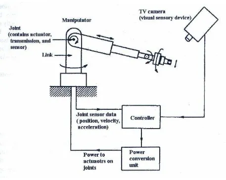
2.2.1.2 Servo-controlled robots
11
Figure 2.5 Servo-controlled arm [3]
2.2.2 Robot Application
12
Figure 2.6 Basic Robot systems
Machine loading, where robots supply parts to or remove parts from other machines. In this type of work, the robot may not even perform any operation on the part, but only a means of handling parts within a set of operation
![Figure 2.1 : Type of robots [4]](https://thumb-ap.123doks.com/thumbv2/123dok/659465.80743/19.595.222.443.506.672/figure-type-of-robots.webp)
![Figure 2.2 : Robot arm and possible workspace [3]](https://thumb-ap.123doks.com/thumbv2/123dok/659465.80743/20.595.100.527.85.325/figure-robot-arm-possible-workspace.webp)
![Figure 2.3: Work space of an articulated robot [3].](https://thumb-ap.123doks.com/thumbv2/123dok/659465.80743/21.595.138.424.150.305/figure-work-space-articulated-robot.webp)
![Figure 2.4 : Non-servo controlled arm [3]](https://thumb-ap.123doks.com/thumbv2/123dok/659465.80743/22.595.136.439.169.356/figure-non-servo-controlled-arm.webp)
![Figure 2.5 Servo-controlled arm [3]](https://thumb-ap.123doks.com/thumbv2/123dok/659465.80743/23.595.158.528.87.314/figure-servo-controlled-arm.webp)