UNIVERSITI TEKNIKAL MALAYSIA MELAKA
DESIGN OF PNEUMATIC GRIPPER FOR COMAU
ARTICULATED ROBOT
This report submitted in accordance with requirement of the Universiti Teknikal Malaysia Melaka (UTeM) for Bachelor Degree of Manufacturing Engineering
(Robotics and Automation) with Honours.
by
FARA NADIA BT MOHD RAFIQ B051110250
920104-11-5374
PROF. DR. BASHIR MOHAMAD BIN BALI MOHAMAD
i
ABSTRACT
ii
ABSTRAK
Laporan projek membentangkan kerja yang dilakukan pada pencengkam pneumatik yang direka untuk COMAU robot di Makmal Robotik, Fakulti Kejuruteraan Pembuatan, UTeM. Objektif projek ini adalah untuk mereka bentuk pencengkam pneumatik dan membangunkan prototaip lembut untuk pencengkam yang direka. Tiga reka bentuk yang telah dicadangkan. Idea-idea ini dibandingkan berdasarkan beberapa kriteria untuk memilih idea yang terbaik. Idea dipilih dibangunkan menggunakan metodologi yang dicadangkan. Idea dipilih telah dibangunkan dengan menggunakan perisian CATIA. Senarai semua bahagian yang perlu direka dan bahagian-bahagian yang standard dibentangkan dalam laporan ini. Lukisan model dan spesifikasi pencegkam telah dibentangkan dengan ukuran yang yang terperinci bagi memenuhi keperluan untuk membangunkan lagi pencengkam. Analisis unsur terhingga (FEA) telah digunakan untuk menganalisis reka bentuk pencengam. Tekanan, anjakan, ubah bentuk dan faktor keselamatan yang diperolehi daripada analisis dan dibentangkan. Kesemua objektif projek yang telah berjaya dicapai. Untuk kerja-kerja masa depan ia dicadangkan untuk mereka-reka, memasang, menguji dan pencengkam direka dan juga memperbaiki reka bentuk pencengkam. Reka bentuk pencengkam perlu diperbaiki (jika perlu) berdasarkan hasil ujian.
iii
DEDICATION
iv
ACKNOWLEDGEMENT
xi
4.1 Solid model of pneumatic gripper 42
4.2 Assembly design of pneumatic gripper 45
4.3 Aluminium Alloy 6061 52
4.4 Solid model of inner jaw 53
4.5 Boundary condition of inner jaw 55
4.6 Static case solution 1 57
4.7 Solid model of outer jaw 62
4.8 Boundary condition of outer jaw 64
4.9 Static case solution 1 66
4.10 Solid model of jaw support 71
4.11 Boundary condition of jaw support 73
xii
LIST OF ABBREVIATIONS,SYMBOLS AND
NOMENCLATURE
COMAU - COnsorsio MAcchine Utensili
CAD - Computer-Aided Design
3D - Third Dimension
CAM - Computer-Aided manufacturing
FEA - Finite Element Analysis
Kg - Kilogram
1
CHAPTER 1
INTRODUCTION
1.1 Introduction
2
3 1.4 Project Scope
a) To design a pneumatic gripper for COMAU Articulated Robot using Computer Aided Design (CAD) software to meet the following requirements:
i. The gripper can handle cylindrical shape of workpieces having diameter up to 50 mm.
ii. The gripper can handle a cylindrical shape of workpieces having weight up to 5kg.
iii. The workpiece will not slip from the gripper fingers
4 are very powerful elements of today’s industry. Different countries have different standards for what they consider a robot. Robotic Institute of America states that a robot is a reprogrammable, multi-functional manipulator that designed to perform tasks that previously done by human. A robot, as a system, consists of the following elements
5
will look more into detail concerning about the articulated robot because this project is based on that type of robot. The next subtopic will briefly explained about the COMAU articulated robot and it’s specifications.
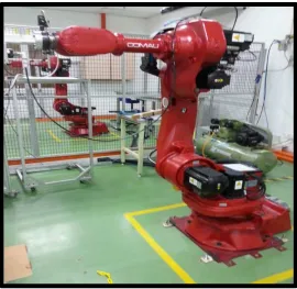
2.1.1 COMAU Articulated Robot
The guideline of the design is made by using the current COMAU Articulated robot manual which is available in laboratory. The COMAU articulated robot used in this research is SMART NS type series 16-1.65 (COMAU Robot Manual, 2005). Smart NS robots occur in various type of application that focused mostly in robotic field. Characteristics of SMART NS family come in highly modular design and referred as the similar operating rules such as in work envelope, payload and reach. Figure 2.1 shows the current COMAU Articulted robot in FKP.
6
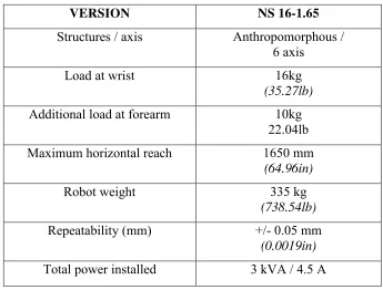
It is very vital to choose the robot application when obtaining the maximum payload. Robot payload is the load or weight for a certain robot arm can lift. Robot payload also refers to the weight of the gripper. Table 2.1 below shows the robot specifications.
7
8
9
2.2 Grippers
Grippers or end effectors are the main component in the robotic system application in order to pick and place object or workpieces within it’s range of axes. So it is important to design the gripper with the first class type of gripper. Omega defines that a gripper is a device that holds an object so it can be manipulated (Omega,2014). The grippers has the power to grip and release the object while some other tasks is performed. Each arm of robot must being constructed with their own degree of freedom (DOF). DOF is meaned by each link and joint must has their limit of size and movement. Moreover, the robot working envelope must be reachable by the DOF of the gripper depend on its angle and configuration of the robot.
2.2.1 Definition and Conceptual Basic of Robot Gripper
The gripper is the only part that has the mechanical contact with the objects and its main functions are to grip objects, hold objects and release objects. Gripping establishes a
10
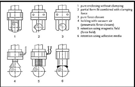
Standard gripper can have two different closing motion which is angular and parallel. The gripper can be categorized into 3 major types which include magnetic gripper, vacuum gripper and mechanical gripper (Rembold, 1990)
Figure 2.4 : Possibilities for prehension of a spherical object (Monkman,2006)
11
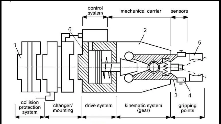
Figure 2.5 : Subsystem of mechanical gripper (Monkman,2006)
Gripper can be equipped with sensors such as shown in Figure 2.5 as a gripping point for supervising the gripping functions. A structured sensor system can supervise the internal state of a gripper( for example, finger distance) and the structure of the environment ( for example, workpiece distance) The functional model of a gripper is modelled as shown in figure 2.6.
Figure 2.6 : Functional model of the gripper Gripper housing