THE EFFECT OF INNER DIAPHRAGMS AND CONTINUOUS SILL SECTION ON
THE STIFFNESS OF AUTOMOTIVE B-PILLAR
ABSTRACT
Tan Chee Fai Mohd. Radzai Said Shamsul Anuar Shamsuddin
Faculty of Mechanical Engineering
(KUTKM)
This paper discusses in detail on the behaviour of T-frame under specific loading obtained experimentally to
investigate the deflection of the vehicle B-pillar. A series of T frame were designed with inner diaphragm at various
location in the sill member in order to investigate the effect of inner diaphragm and non-continuous closed hat
section in the sill member. These two types of specimens were employed to show the effects of different types of sill
member on the stiffness of the overall structure. The finite element analysis and experimental test were carried out
on the in-plane bending. The experimental results were compared with the finite element analysis results to
demonstrate the effectiveness of the inner diaphragm in the automotive 8-pillar. Based on the results obtained from
the experimental work, location of baffles for the specimens do not gives any major influences for in-plane bending
case due to the shape and direction baffles are not .suitable. From the results, the specimen with baffles located at
the weld line is stiffer than the other specimens.
KEYWORDS
Vehicle T-frame, inner diaphragm, continuous closed hat section, experimental methods, finite element analysis
I. INTRODUCTION
The framework of the automotive body structure is comprised of thin walled section members in the formed of overlapping sheet metal fastened by spot-welds. In analysing the structure of the vehicle body, it is assumed that the intersecting angles at which member are joined together, varies according to the external forces. The automotive frame joints are subject to dynamic and static loads. The dynamic 。ョ。ャセウ⦅ゥウ@ can be carried out using matrix methods provided the overall stiffness. The mass distribution is known but it is difficult to find a suitable approach for
damping properties. However, damping effects are less than inertia and stiffness ・ヲヲ・」lセN@ The static analysis can be
Seminar Pencapaian Penyelidikan KVTKM 20l:\5
used to find the force-displacement relationships of the frame joints. Static analysis in general includes the
calculation of deformations and internal forces such as bending moments, torques, bi-moments, longitudinal and shear forces. Experiments and finite element analysis can be used to determine joint rigidity. Although tltis
framework is accounting for only a small part by weight of the entire vehicle but it exert a substantial effect on the response of the vehicle structure.
The effective design of the vehicle T-frame will maximise the safety of the passengers and reduce the vehicle
weight. The automotive industries have been working hard to reduce the vehicle weight in order to achieve better fuel efficiency and to reduce global environmental problems. Furthermore, in improving the safety of passengers in a collision, it will be benefit to decrease the maximum load that occurs during the collision. This can reduce the
level of occupant's injury and control the deformation of the structure to ensure a sufficient safe space for occupani
[9].
Therefore, in order to reduce the vehicle body weight and simultaneously maintaining satisfactory functioo, · performance and engineering reliability, it is extremely important to establish a consistence procedure in analysing and evaluating the frame joint behaviour. Noted that, although the frame joints are only a small part of the entire vehicle, they exert a great influence on the structure system.
The goal of this work is to evaluate the designed of inner diaphragm into the automotive T-frame at several location on continuous sill member. The specimens were employed to show the effects of different location of
baffles and in continuous sill member on the stiffness of T-frame structure. A special mechanical test rig was designed and manufactured in order to test the T-joint. Experimental test and finite element analysis were canied out. The results obtained were analysed.
2. RELATED WORK
There have been numerous researches involving joint stiffness of the automotive body structure related to
thin-walled structures in which the studies are on fastened method, flexible characteristics, collapse behaviour, torsional problems and stress distributions. These studies were conducted since the frame joints give a very important affect on the vehicle response. Moreover, most of the studies found that the s tiffness of the frame joints greatly influenced on the overall stiffness of the vehicle body structure.
McGregor et al. [I] developed a joint design approach for adhesively bonded and spot welded aluminium automotive structures. The approach includes an allowance for joint geometric variables.
manufacturing variability and complex joint loading. An important aspect in the development of the approach to minimise the detail required to model the joints in a full vehicle model. The accuracy of the
149
The Effect Of Inner Diaphragms And Continuous Sill Section On The Stiffness Of Automotive B-Pillar
approach is demonstrated on a simple structure subjected to complex loading, and the use of the approach is
illustrated on a full vehicle.
Sunami et al. [2] performed their analysis on the joint rigidity of the automotive body structure both in
in-pJane and out-of-plane bending of plane joint structures. They have made a fundamental study of the joint
rigidity involving T or L shaped thin walled box beams and examining several factors that caused the rigidity
to be reduced. In their work, they used a theoretical equation; i.e. the theory of shear tiow and the results
confirmed by experimental values. For the in-plane study, they have concluded that the joint rigidity of box beams
depends on the "release" (insufficient constrained condition) and shearing deformation and elongation of joints. From
this study the analysis of fundamental behaviour of joints can be used as a step to plan structural designs. Shannan et
al. [3) did a comprehensive study on the effect of local detail on the stiffness of car body joint. Three joints between
the structural members meeting the roof of a small car were tested for stiffness in the plane of the side frame.
Niisawa et al. [ 4] conducted an analytical method of rigidities of thin-walled beams with spot welding joints and
its application to torsion problems. In their study, they have discussed the elastic properties of the spot welding joints in the transmission of the shearing forces and developed the method based on shear flow theory in introducing the
elastic properties of spot welding joints into the structural analysis of thin-walled beams. Based on this study, they
found that the welding point at the middle station transmits the maximum shearing forces and the torsional rigidities
not only depend on the length of beams but also on the pitch of welding points.
Ishiyama et al. [10) did a study on the collapse behaviour of thin-walled beams under torsional moments. The
collapse tests were made a square and rectangular section tubes (closed section), a hat section beam closed by spot
welding (semi closed section) and channel beams (open section). Based on the geometry of the cross sections and
material properties of the beams, they have discussed the yield and maximum moments in the collapsing process and
clarified the effect of constraints against warping deformation on yielding moment for the channel beams.
Vayas et al. [5] developed a method for calculating the carrying capacity and the deformation characteristics of
the joints. Static and kinematics limit state models were presented which allow the ultimate strength to be
determined from closed formulae.
For the finite element analysis, Shakourzadeh et al. [6] deals with the finite element fuµnulation for the
analysis of space frames. A numerical method is presented to take into account the deformatfon of the joint
connections in linear, non-linear and stability analyses of three-dimensional thin walled beam structure. Moon et al.
[7] presented a joint modelling methodology where the definition and assumptions of the joint are discussed. In addition, the joint stiffness analytical model is proposed using static load test results, also presented the sensitivity
analysis method and a joint stiffness-updating algorithm. To verify these methods, the FE analysis results of a half
size structural model of an automobile with rigid joints and rotational spring joints are compared with experimental
Seminar Pencapaian Penyelidikan KUTKM 200(;
analysis results. Farooque et al. [8] proposed the finite element formulation to incorporates rectangular plate and edge boundary spring elements. The model is then used to determine the punching shear and rotational stiffness of both double chord T-joints and single chord T-joints, thus demonstrating its versatility. The numerical values obtained are in good agreement with the experimental results available in the literature.
3. FUNDAMENTAL ASPECT OF THE SPECIMEN
The specimens were made of cold rolled mild steel. It is consisted of five components, which are the base plate, inner diaphragm (baffles), vertical member, horizontal member (sill) and the jointing member. Once constructed, it formed a T-joint member with 75mm comer radius at the jointing area and with closed hat section
members and spot welded along its flanges as shown in Figure l.
The base plate was a planar sheet with l .2mm thickness in the form of T-shape with 55mm comer radius. The horizontal member is an open hat section with 20mrn flanges over the complete length and having the same
thickness as the base plate. It is connected to the base plate by means of spot welds at the pitch distance of 50mm. Before these two components are connected, the inner diaphragms are connected to their particular
locations in the horizontal member by means of three spot welds at two equal pitches all the way round except エセ・@ one that faces the base plate. This has been plug welded at two equal distances with the base plate. The purpose of having
these holes and extension length is to build a box of cement block at each end so that it can be regarded as fixed ends.
The vertical member is connected to the base plate by means of spot welds. This assembly is connected to a connecting plate with dimensions of 180mrn X l80mrn X lOmm at the top part of the assembly by means of C02 ;11< welding. The purpose of having the connecting plate is to ensure that the vertical member will move as one entity when loads are applied.
The jointing member connects the base plate, vertical or horizontal member by means of spot welds, fillet welds, plug welds and C02 arc welds. Plug welds were used in any area where spot welding electrodes were not
accessible due to the shape of the T-joint. Although the jointing member was designed as a single piece, in real case it was made from three pieces of steel which are joined by one C02 arc welding operation due to the lack of production tools. In production cars the hat section of the sill and 'B' post are formed as oiie pressing. In this attempt, the work tried to simulate this without the facilities of press tools.
3.1 Specimen Design
·It.
1 O'[fnner Diaphragms And Continuous Sill S ection On The Stiffness Of Auto11Wtive B-Pillar fh e E11 ec
In this work, the specimen have been constructed with three parts which used a continuous sill member. The inner diaphragms have been located in-line with the sides of B-pillar (AMl), at the weld line (AM2) and at the outside of the weld line (AM3). The detailed of the specimen is shown in Table 1. Figure 1 shows the parts of the
[image:5.603.83.390.180.400.2]specimen.
Table 1 Specimen types: Continuous Horizontal Member.
Specimen's Identity AMl AM2 · AM3
Location of Baffles 160mm 272mm 40mm
(Left and Right)
Figure 1: Parts of specimen
3.2 Experimental
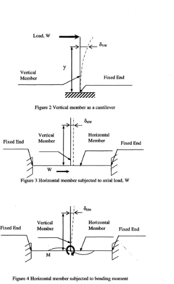
The In-plane bending case was considered in the experimental testing. The load applied at the top part of the vertical member and in parallel with the horizontal member as shown in Figure 2, Figure 3 and Figure 4. The total displacement can be written as:
(1)
152
Load, W
Vertical Member
y
Seminar Pencapaian Penyelidikan KUTKM 2006
)
Fixed End
Figure 2 Vertical member as a cantilever
Fixed End
Vertical Member
. セ@
セ N セ@
I
Horizontal Member
Fixed End
Figure 3 Horizontal member subjected to axial load, W
Fixed End
Vertical Member
M
Horizontal
[image:6.600.149.495.79.645.2]Member Fixed End
Figure 4 Horizontal member subjected to bending moment
Introduction of these rotational assumptions, the experimental and finite element analysis of the stiffness of the
joint can be easily obtained. From experimental test, the total displacement can be measured, while the displacement
153
The Effect Of Inner Diaphragms And Continuous Sill Section On The Stiffness Of Automotive B-Pillar
of each member due to deformation of a beam can be calculated using beam theory or finite element analysis. In addition, the displacement at the loading point can be incorporated in function, which includes the angular stiffness
of the joint.
To conduct the in-plane experimental testing, a mechanical test rig was designed and manufactured. The test rig was built to be flexible and accurate. The test rig was equipped with tensile gauge, turnbuckles, a clamping set,
Dexion frame and dial gauges.
4. RESULTS
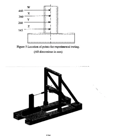
In-plane bending, 4 interest points were measured at the specimen. These points were labelled by W, X, Y and
z
(see to Figure 5). Figure 6 shows the in-plane bending experiment .on the test rig.I
w
Iセi@
460 I r
x
II
_,
360 セ@
y
260
-z
-i
145 セ@
i
[image:7.597.81.459.280.724.2]---1---MMMMMMMMMMMMMセMMMMMMMMMMMMMMM
Figure 5 Location of points for experimental testing. (All dimensions in mm)
Seminar Pencapaian Penyelidikan KUTKM 2 006
Figure 6 The in-plane bending experiment on the test rig
4.1 In-Plane Bending Test Result for Specimen AMl
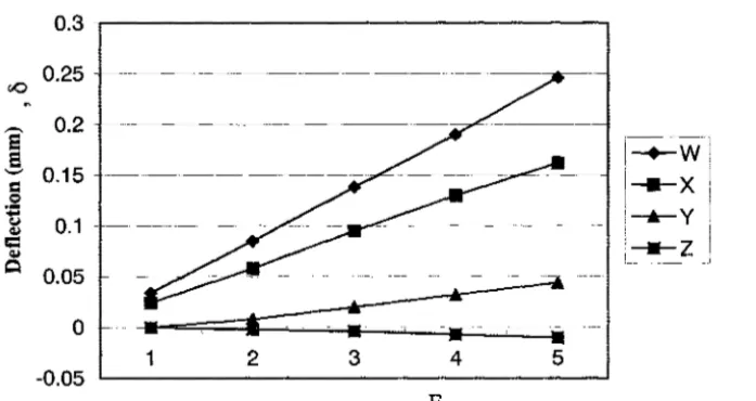
[image:8.606.129.478.299.484.2]Specimen AMl is a continuous sill member with the baffles located at the weld line i.e. 160 mm left and right from the centreline of the T-joint. The linear of displacement with load occurred at point W, X, Y and Z is shown in
Figure 7.
0.3 - . - - - .
0.25
,___ 0.2
セ@
=
0.15 0:e
Q,Ic
Q,I
セ@ 0.05
0
-1 2 3 4 5
-0.05 _..__ _ _ _ _ _ _ _ _ _ _ _ _ _ _ _ _ _ __.
Loads (N) 'F
Figure7 Deflection vs. load (Linearity Displacement)
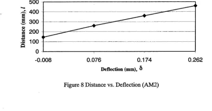
4.2 In-Plane Bending Test Result for Specimen AM2
This specimen is a continuous sill member with the baffles located at the outside' of the weld lines i.e. 272llJlll left and right from the centreline. The experimental results for AM2 as shown in Figure 8. Figure 8 show the
deflection versus distance (location), where it is constructed based on maximum load applied.
t O'f/nner Diaphragms And Continuous Sill Section On The Stiffness Of Automotive B-Pillar
'{/leE!fec
500 LNNNMMセセセセセセセセセセセセセセセセセセセMMMML@
,,.:; 400
e
,§,
300セ@
セ@ 200 KMMセMMM]@
セ@セM 100
s
0 MAMセセセセセセセセセセセセセセセセセセセセセMMMA@
-0.008 0.076 0.174 0.262
Deflection (mm), b
Figure 8 Distance vs. Deflection (AM2)
4.3 In-Plane Bending Test Result for Specimen AM3
The specimen is a continuous sill member with the baffles located in-line with the vertical member, i.e. 40mm
left and right from the centerline. he experimental results for AM2 as shown in Figure 9. The graph of deflection
versus distance (location) is constructed based on the maximum load applied. Figure 9also shows that negative
displacement existed at the joint region, i.e. point Z. This is the bowing effect due to compression.
500 セセセセセセセセセセセセセセセセセセセMGiMᆬMMセセ@
セ@
e
400!
300GI
セ@ 200
=
!!l
100セ@ PKMセセセセMNLNMセセセセセセセセセセセセセセセMMQ@
セPNPPX@ 0.084 0.189 0.268
[image:9.595.50.397.65.246.2]Deflection (mm) , b
Figure 9 Distance vs Deflection (AM3)
156
Seminar Pencapaian Penyelidikan KUTKM 2006
4.4
Deflection of Vertical Member and Joint Region of Continuous Sill Member
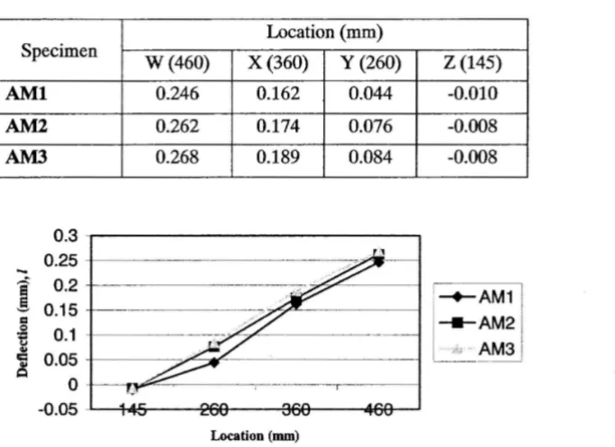
[image:10.597.136.478.161.409.2]The results obtained based on 900 N longitudinal load to specimen Type 1 can be seen in Table 2 and Figure 10.
Table 2 Deflection of vertical member and joint region Type 1
Location (mm) Specimen
w
(460)x
(360) y (260)z
(145)AMI
0.246 0.162 0.044 -0.010AM2 0.262 0.174 0.076 -0.008
AM3 0.268 0.189 0.084 -0.008
0.3 0.25
i
0.2g
0.15=
Q
0.1
tZ
セ@
0.05
=
セ@1
-.-AM1 I
QMM] M Zセ i@
Q
0 -0.05
Location (mm)
Figure 10 Deflection of vertical member and joint region of continuous sill member (Unit: mm)
Based on Table 2 and Figure 10, it suggested that,
a. Location of baffles on a continuous sill member does not give any major influence on the in-plane bending
case. However, among these specimens, the specimen with baffles located at the weld line is stiffer than the baffles located with the side of B-pillar.
b. No matchbox effect occurred in these types of specimens.
5. FINITE ELEMENT ANALYSIS
The modelling of the specimen has been carried out to simulate the actual joints of a vehicle. The entire finite element (FE) consisted of four main parts i.e. base plate, vertical member, horizontal member and inner diaphragm
(baffles) were modelled. The model was created using square corner (i.e. no comer radii) in order to reduce the process time.
157
E·fFect Of Inner Diaphragms And Continuous Sill Section On The Stiffness Of Automotive 8-Pillar [he '))'
The model were constructed using thin shell element without considering the solid modelling since the
thickness of the plate is I .2mm which thin enough to neglect the thickness effect. A mapped meshed were used throughout the construction of the model in order to get better accuracy. Moreover the model is free from irregular
shape. A four nodded simple rectangular elements were used for mapped the meshing.
The top surfaces of the vertical member were constrained using rigid element so that it can be moved as a
unit when the loads were applied . The base plate and both vertical member and horizontal member were
connected by means of beam element (representing spot welds) at the pitch distance of 50mm. The inner
diaphragm are connected to their particular location in the horizontal member by means of three beam
elements at two equal pitches all the round. Both ends of the horizontal member were fully restrained from
any degree of freedom, which represent as fixed ends. Two point forces were located along the edge (on the
nodes) of the top surface of the vertical member (i.e. facing the direction of the force). 900 N forces were used
for in-plane bending case. The longitudinal force of 900 N was applied at the top of the vertical member.
5.1 Finite Element Results
For the Finite Element (FE) analysis, the locations for the measurement are quite similar to the location in manual
testing. The locations for measurement were slightly deviates from because the location of the nodes is quite
difficult to be on the same position. In this Finite Element (FE) analysis, tolerance of ±5mm has been given for the locations of the measurement.
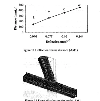
ModelAMl
The results obtained from the FE analysis are shown in Figure 11. The deformed model is shown Figure 12. It
can be seen that the joint region of the vertical member and the centre region of the horizontal member were largely
deformed.
158
ModelAM2
-
セ@ 400e
,§,
300セ@
200セ@
100Q
0.016
Seminar Pencapaian Penyelidikan KUTKAf Rセ@
0.077 0.16 0.244
[image:12.613.178.499.85.407.2]Deflection (mm)' b
Figure 11 Deflection versus distance (AMl)
Figure 12 Stress distribution for model AMl
The stress distribution appeared in model AM2 is quite similar to AMl when longitudinal of 900N was applie< the top of the vertical member. The results as shown in Figure 13, the graph shows no negative displacerr occurred and therefore no occurrence of local bending at the particular point of measurement. High stress appe2 to be along the flanges at the corner radii region.
[image:12.613.216.449.101.280.2]'[he Effect Of Inner Diaphragms And Continuous Sill Section On The Stiffness Of Automotive B-Pillar
ModelAM3
-8
400!
300.セ@
セ@ 200
.s
"'
Q
1000.009 0.075 0.161 0.248
[image:13.598.108.362.75.206.2]Deflection Hュュセ@ セ@
Figure 13 Deflection versus distance (AM2)
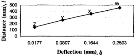
The results obtained from FE analysis for AM3 are shown in Figure 14. The stress for AM3 is concentrated along
the flanges in the comer radii region. The model AM3 have baffles located in-line with the vertical line, therefore it prevents the model from being largely deformed at the center region. However, it starts deformed immediately after
the right baffle.
-!
300B
200セ@ 100
..
i!:j
• :-a 0 KMMMMMNMMMMMMLNNMMMMMMMMセ@
Q
0,0177 0.0807 0.1644 0.2503
[image:13.598.122.350.377.470.2]Deflection (mm), セ@
Figure 14 Deflection versus distance (AM3)
5.2 Deflection of Vertical Member and Joint Region of Continuous Sill Member
The results obtained based on 900N longitudinal load applied to T-flames in FE analysis are presented in Table 3 and Figure 15.
Table 3 Deflection of vertical member and joint region (Unit: mm)
Location
w
x
yz
AMI 0.244 0.160 0.077 0.016
AM2 0.248 0.161 0.075 0.009
AM3 0.250 0.164 0.081 0.018
[image:13.598.112.349.629.677.2]Seminar Pencapaian Penyelidikan KUTKM 2 006
"°
ゥZセ ᄋセ⦅Z[
] セ@
-e
o.3t
l
セ@ PNPセ@
Z M MMᄋ セ
M MM
-- - --- --143.6 261.2 358.9 456.6 Location (mm)
' --+-AM1 i
!-AM2 i
[ セ@ AM3
!
[image:14.610.147.418.88.196.2]l _ __ _ __ __ .o
Figure 15 Deflection of vertical member and joint region of continuous sill member (Unit: mm)
Based on Table 3 and Figure 15, the following are the pre-conclusion that can be drawn.
a. Model AMl is stiffer than the other two models. However as the locations of measurement is nearer to the joint area, model AM2 shows that it is the stiffest among the models
b. No 'match box' effect occurred.
6. CONCLUSIONS AND DISCUSSION
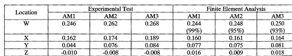
The results obtained from experimental analysis and finite element analysis is shown in Table 4.
Table 4 Displacement of vertical member due to longitudinal load of 900N
Location Experimental Test Finite Element Anal 'Sis
AMl AM2 AM3 AMI AM2 AM3
w
0.246 0.262 0.268 0.244 0.248 0.250(99%) (95%) (93%)
x
0.162 0.174 0.189 0.160 0.161 0.164y 0.044 0.076 0.084 0.077 0.075 0.081
z
-0.010 -0.008 -0.008 0.016 0.009 0.018From Table 4, it can be seen that the results obtained from FE analysis gave deflection within the range of 93%
to 99% of the experimental test. The results are acceptable; however, if the quality of the specimens were good
(experimental test) or if the 'arc welding' were considered at the joint region in FE analysis, the results might be in
good.
There are differences of the results in both analyses especially at point Z. From FE analysis, there are no negative displacement occurred at point Z (i.e. no occurrence of local bending). These results seem to be
contradicted with the results obtained from the experiment test but the reason can be found in the quality of the
specimens. In the experimental test, the specimens have undergone an arc welding operation, which might have
161
[image:14.610.41.509.437.527.2]The Effect Of Inner Diaphragms And Continuous Sill Section On The Stiffness Of Automotive B-Pillar
reduced the strength of the specimen at the joint region. The results show that specimen AMI is stiffest model and AM2 is stiffer than AM3. The results show that spot welds are far from yield stress and there do not give major influences on the experimental test.
Based on the results obtained from the experimental work, location of baffles for the specimens has no influences for in-plane bending case due to inappropriate shape and direction baffles. However, the specimen with baffles located at the weld line is stiffer than the other specimens.
ACKNOWLEDGMENTS
The author gratefully acknowledges the financial support from Kolej Universiti Teknikal Kebangsaan Malaysia.
REFERENCES
[I] McGregor, I. J., Nardini, D., Gao, Y. and Meadows, D. J. (1992). Development of A Joint Design Approach for Aluminium Automotive Structures, SAE Technical Paper Series, 922112: 1-13.
(2] Sunami, Y., Yugawai, T. and Yoshida, Y. (1998). Analysis of joint rigidity in plane bending of plane-joint, JSAE Review, 9(2):13-19.
[3] Sharman, P.W. and Al-Harnmoud, A. (1987). The effect of local details on the stiffness of car body joints, International Journal of Vehicle Design, 8(4/5/6):526-537.
[4] Niisawa, J., Tomioka, N. and W. Yi. (1984). Analytical method of rigidities of thinwalled beams with spot -welding joints and its application to torsion problems, JSAE Review, 11(3):45-49.
[5] Vayas, I. and Briassoulis, D. (1993). Behavior of Thin-Walled Steel Frame Joints, Journal of Constructional Steel Research, 24(2): 105-119.
[6] Shakourzadeh, H., Guo, Y. 0. and Batoz, J. L. (1999). Modeling of Connections in the Analyses of Thin-Walled Space Frames, Computers and Structures, 71(4):423-433.
(7] Moon, Y. M., Lee, H. and Park, Y. P. (1999). Development of An Automotive Joint Model Using An Analytically Based Formulation, Journal of Sound and Vibration, 220(4):625-640.
[8] Mirza, F. A., Shehata, A. A. and Korol, R. M. (1982). Modeling of double chord rectangular hollow section T-joints by finite element method, Computers & Structures, 15(2): 123-129.
[9] Shafie, M. H. ( 1998). The effect of non-continuous sill section on the stiffness of B ーゥャャセL@ to sill joints. M. Sc. Thesis, Cranfield University.
[IO] Isiyama, S., Yamamoto, K., Takugi, J., and Mizutani, Y. (1982). Collapse behaviour of thin:..walled beams under torsional moments. JSAE Review, 3(1):4-10.