SA)D , M.R., YU(AZR) , M.Y. and SA)JOD LAU
Hang Tuah Jaya, 76100 Durian Tunggal, Melaka, MALAYSIA. 1
Jalan Ayer Keroh Lama, 75450, Melaka, MALAYSIA. 3
1.0 INTRODUCTION
)mpact energy absorption )EA has been studied by many researchers. Recently Olabi et al. have
reviewed )EA with respect to metallic tube. (owever, very recent paper reviewed by Saijod et al. , on the
composite material. There many types of )EA devices used, one them are a ring subjected to lateral loading. The
energy absorption capacity of a ring under lateral compression was first addressed by Mutchler . Two
different kinematically admissible collapse mechanism that produce the same post-collapse load-deflection characteristic when employing a rigid perfectly-plastic material model were put forward by DeRuntz and (odge
and Burton and Craig . Careful and exhaustive experiments on the crushing of tubes and rings
done by Reddy and Reid led to the formation of a model that is based on the classical elastica theory that
used a rigid linear strain hardening material behaviour, Reid and Reddy . As a result of this analysis,
load-deflection curves were seen in very good agreement with experimental observations. This analysis has since
come to be known as “plastica" after being addressed by several authors starting with Yu and Johnson .
Reddy and Reid examined the behaviour of laterally compressed tubes under transverse
constraints and noticed that the collapse load increased by a factor approximately . and the energy absorbed increased by a factor of in comparison with transversely unrestrained tubes. An excellent review of the energy
absorbing systems, that use the lateral compression of metal tubes is given by Reid , .
Plastic collapse of square tubes compressed laterally between two plates was studied by Sinha and
Chitkara who produced plastic collapse mechanisms. Gupta and Ray have performed experiments
on this-walled empty and filled square tubes laterally compressed by using a rigid platen. They analysed the
problem with the Sinha and Chitkara mechanisms and assumed plastic hinges occurred at only at mid
section of vertical side, while in horizontal side to be elastic bending. These analyses used plastic hinges and
could be modified by replacing plastic hinges with plastic zones Reddy, . Gupta and Sinha have
studied the post-collapse behaviour of square tubes under transverse loads applied by flat short-width indenters as well as considering tubes compressed between an indenter and a rigid platen.
Johnson and Reid cited the energy absorbing devices with hexagonal shapes referring to an article
of Fuse and Fukuda, in Japanese where in hexagonal tubes under quasi-static compression across faces
were studied. The mechanism of collapse has hinges at the side corners and at the centres of loaded faces. Although the collapse load is in good agreement with experiment, the theory overestimates the post collapse loads. No alternatives collapse mechanisms appears to have been considered. The case of hexagonal ring loaded
ABSTRACT
Lateral crushing of hexagonal ring under quasi-static loading were analysed using ABAQUS/Standard Finite Element (FE) Method package. The modes of deformation and load-displacement characteristics were predicted and the same were compared with experimental results. The material modelling of elastic-perfectly plastic and nominal stress-plastic strain were compared. The experimental results found that the quarter model using CPE6H with elastic-perfectly plastic material is good enough to obtain a satisfactory result.
Keywords: Lateral Loading, Finite Element Analysis, Absorbing Mechanism.
across its diagonal has not been studied numerically so far. This paper presents the Finite Element Method to
study the accuracy with experimental results done by Said and Reddy .
2.0 MODELLING OF HEXAGONAL RINGS
Two material models were used for as-received material. First, the nominal stress-plastic strain data from the tensile test were used to describe the material. Secondly, the material was modelled as elastic-perfectly plastic. The results of the two materials were compared. For the annealed material, the nominal stress-plastic strain data from tensile tests were used to adequately model the strain hardening effects. The stress-strain data used are graphically shown in Figure .
(a) (b)
Figure 1: Material properties used in ABAQUS analyses model (a) As-received material, (b) Annealed material.
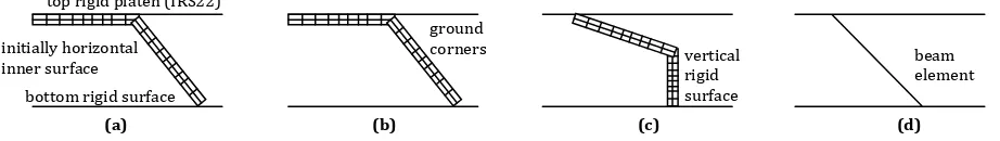
Taking advantage of symmetry about two axes, only one quarter of the ring was modelled. Simple and side constraints lateral compression were examined for both across faces and corners loading. (owever, in this paper, simple lateral compression is only considered. Typical geometry and element mesh for several cases are shown in Figure . The depth of the model considered was mm and thickness was . mm. The case of ground corners in solid elements model Figure b were also examined. Beam elements with quarter, half and full ring model were also used in the case of loading across faces to study the accuracy of ABAQUS/Standard Finite Element code.
(a) (b) (c) (d)
Figure 2: Typical geometry and mesh of quasi-static analysis using ABAQUS with solid and beam elements (a) non-ground corners model
compressed across faces, (b) ground corner model compressed across faces, (c) ground corners model, side constraints and compresses
across faces, (d) beam element model compressed across faces.
2.1 Solid Elements.
Forty eight six-noded elements CPE ( , quadratic plane strain triangle and hybrid made up a quadrant of the specimen without ground corners. )t was found that typically a mesh consisting of mm base by
. mm height triangular element was good enough to accurately predict experimentally results. The
typical mesh for non-ground and ground models is shown in Figures a and b, respectively for the case of simple compression across faces.
The model with ground corner for the case of simple compression across corners is shown in Figure c. The mesh and geometry used to model compression across faces was employed. A rigid surface
element )RS monitored the contact between the flat, horizontal rigid surface top and bottom platen
and the specimen, in the case of simple compression Figure a and b . The rigid platen was modelled as a rigid surface with the *R)G)D SURFACE and located on the top model surface. *SURFACE DEF)N)T)ON option was used to define outer surface of model. The *CONTACT PA)R option then was used to model the contact between the outer surface and rigid platen. The inner surface of the specimen that came into contact with the central rigid platen axis of symmetry was defined by means of an interface element
)RS to avoid penetration. The effect of friction was considered by taking the coefficient of friction,µ as
)n modelling the ground corners, the corner lines were chamfered to thickness, which was the same as side thickness. The typical mesh of ground corners model is shown in Figure b. The corner was modelled with smaller solid elements of CPE (. The element size except at the corners was mm base by
. mm height. The total number of CPE ( elements and nodes were and , respectively, which is
shown in Figure b.
2.2 Beam Elements.
The B beam element used had a three-noded quadratic. Each side wall had elements of mm length, and hence there were elements in the model of full hexagonal ring. A typical quarter model is shown in Figure d for loading across faces. As in the solid element, the rigid platen was modelled as *R)G)D SURFACE, but its location was in mid-section of the hexagonal ring. This three noded quadratic beam element uses Timoshenko beam theory, which allows large strain deformation and includes transverse shear deformation.
3.0 RESULTS AND DISCUSSION
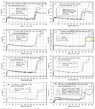
The load-displacement curves are shown in Figure a until Figure h . The deforming meshes are shown in
Figure and Figure for solid elements meanwhileinFigure and Figure is for beam elements.
NOTE : EPP for elastic-perfectly plastic, NSPS - nominal stress-plastic strain, NG - non-ground and G- ground
Figure 3: Load-displacement curve of hexagonal rings laterally compressed across faces (a) Solid elements CPE ( and CPE ( , beam
element B and experiment, (b) Quarter, half and full model, ABAQUS analysis with B element, (c) Elastic perfectly-plastic, nominal
stress-plastic strain material model with ABAQUS and experiment, (d) ABAQUS CPE ( and experiment for annealed material, (e) ABAQUS
m= and m= . and experiment, (f) ABAQUS CPE ( and experiment for NG corners, (g) ABAQUS CPE ( and experiment for G corners,
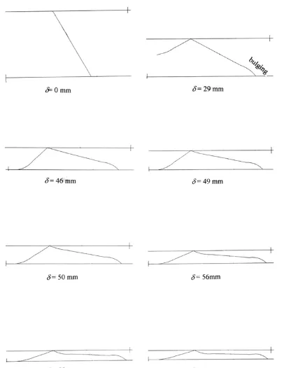
Figure 4: Deformation of a ring non-ground corners compressed across faces predicted by ABAQUS with solid elements CPE ( and
elastic perfectly plastic material.Only quarter of the ring shown.
Figure 5: Deformation of a ring ground corners compressed across faces predicted by ABAQUS with solid elements CPE ( and elastic
perfectly plastic material. Only quarter of the ring shown
Figure 6: Deformation of a ring ground corners compressed across faces predicted by ABAQUS with beam elements B and elastic
Figure 7: Deformation of a ring compressed across faces predicted by ABAQUS with beam elements B and elastic perfectly plastic
material. A full model of the ring shown
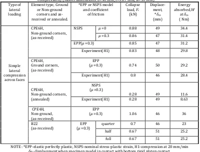
A summary of FEM results of rings compressed across faces is as presented in Table . The summary
results include the collapse load, Fc displacement when the top and bottom ring faces touch, δtb and energy
absorbed, W of experimental results
.
Table 1: A summary of FEM results of lateral compression on hexagonal rings simple lateral compression and side constraints
compression . model dimensions: b= mm, t= . mm, w= mm
NOTE : *EPP-elastic perfectly plastic, NSPS-nominal stress-plastic strain, ( -compression at mm/min
δtb- displacementwhen specimen model in contact with bottom rigid platen contact.
Four parameters are discussed in this section to check the accuracy of FEM. Those are geometric modelling, material modelling, friction and corner grinding effect
(i) Geometric modelling.
a) Solid element CPE6H, CPE4H and beam elements (B22).
Figure a illustrates a comparison of experiment with the load-displacement curves produced by the
and quarter models were used. A coefficient of friction, . was used and the material was assumed to be elastic-perfectly plastic. )t is seen that the curve produced with six noded, quadratic, triangular plane strain hybrid pressure elements type CPE ( is in close agreement with the experiment, the difference < %. Bending in elements is dominant in the CPE ( quadratic element, which is important in the present deformation process. This can also be seen in deforming mesh shown in Figure a-b. This is not the case with the CPE ( model. As a result, load-displacement curve predicted by CPE ( elements overestimates the experiment by about > % at collapse Figure a and the difference gradually decreases to about % when central sections of the ring come into contact with each other. This may be due to the fact that no bending effects are allowed in the bilinear element CPE (, thus enhancing the load. The agreement may be closer with a finer element mesh. On the other hand, beam element B underestimates the experimental results by ranging from about % at collapse and % at the onset of contact. This may be also due to fact that, the beam element is one dimensional and the variables such as stresses, strains are functions of position along the beam axis only.
b) Quarter, half and full models with beam elements.
Figure b shows the load-displacement curves obtained using quarter, half and full ring models
employing beam element B in the ABAQUS package using an elastic-perfectly plastic material model
for all cases. All the models produce identical characteristics except that the inner upper part come into contact with rigid body in the quarter model at a displacement of mm total mm and with the inner lower part in case of half and full ring models, at a displacement of mm. The deformation patterns produced by the quarter and full model analyses are shown in Figure and Figure . A bulging begin to form at the side corners at a displacement of mm in all three cases, it continues until the model is completely crushed. The reason for this bulging is not clear and is not explored. The half and full ring models produced identical behaviours throughout the displacement regime. This analysis indicates that the quarter ring model is good enough to obtain results that agrees well enough with the experiment.
(ii) Material modelling.
a) Elastic-perfectly plastic and nominal stress-plastic strain curve for as-received material.
Figure c shows the two load-displacement curves predicted using the two material models, i.e. elastic-perfectly plastic and nominal stress-plastic strain curve for the case of as-received material along with the experimental characteristic. The analysis was carried out using solid elements CPE ( and non-ground
corners with µ = . . The predictions of the two material models are identical. Table shows that the
collapse load and energy absorbed are the same for both cases. (ence, it may be inferred that the elastic-perfectly plastic model produces results as accurate as the nominal stress- plastic strain curve for the as-received material. This is also good enough to predict the experimental result by using elastic-perfectly plastic model. (owever, the differences between prediction and observation in the elastic region are slightly higher than in the post collapse regime. This might be due to small curvatures at corners and any non-uniformities in thickness in the experimental specimen The deformed shapes predicted with the elastic-perfectly plastic material model are plotted in Figure .
b) A nominal stress-plastic strain curve for annealed material.
Figure d shows the predictions using nominal stress-strain curve for an annealed mild steel ring along with the experimental characteristics. The analysis used CPE ( solid element and non-ground corners in
the model with µ = . . The numerical load-displacement characteristic shows close agreement with the
experimental results. The collapse load, Fc and displacement, δtb where the load begins to steeply increase,
for both cases are the same, which is about . kN and mm, respectively row in Table . There are also no significant differences in the predicted and observed deforming patterns.
(iii) Frictional effects.
The FE model used CPE ( element and non-ground corner case. Nominal stress-plastic strain curve was
used for the as-received material of the ring. Figure e shows the of load-displacement curves with
coefficient of friction values of and . and indicates that friction has negligible effect on the collapse load and has marginal effect maximum of % on the post collapse loads. (owever, in the frictionless model, the inner central faces come into contact at a displacement of mm, mm smaller than that when friction is included. These are shown as points c and c in Figure e.
(iv) Influence of corner grinding.
Figure fandFigure g illustrate the load-displacement curves for rings with non-ground and ground
corners crushed across the faces. CPE ( elements with µ = . are used in the FE analysis, which is
compared with experimental results. The slope of the elastic line in load-displacement curve for ground corners model is closer to the experiment curve, as seen in Figure g. There was a slight blip that appears
in the case of ground corners at about mm displacement on curve at k, as the rigid platen came into
The inner mid face came into contact with the bottom rigid surface at a displacement of mm in ground
case, while in non-ground case this was at mm Figure fandTable . The deforming meshes at these
displacements are shown in Figure and Figure . )n general, the load-displacement curve for non-ground model is slightly higher by a maximum of approximately % compared with experimental curve while for ground cases, they are in close agreement.
4.0 CONCLUSION
Experiment suggests that the elastic-perfectly plastic model produces results as accurate as the nominal stress-plastic strain curve for the as received material and the quarter ring model is good enough to obtain a satisfactory result. )t shows that solid element, CPE ( produced the best results. The friction has negligible effect on the collapse load and has marginal effect on the post collapse loads.
REFERENCES
[
] Burton, R.(. and Craig, J.M. : An )nvestigation )nto The Energy Absorbing Properties Of Metal TubesLoaded )n The Transverse Direction. Thesis for B.Sc., University of Bristol.
[ ] DeRuntz, J.A. and (odge, P.G. : Crushing of a Tube between Rigid Plates. J.Appl. Mech., vol. , pp.
-.
[ ] Fuse, (. and Fukuda, (. : Plastic Deformation Characteristics Of Polygonal Cross Section Cylinders.
Meiji University Department of Engineering, Report No. - , )- , .
[ ] Gupta, N.K. and Sinha, S.K. : Collapse of a Laterally Compressed Square Tube Resting On a Flat Base.
Int. J. Solid Structure, vol. , no. / , pp. - .
[ ] Gupta, N.K. and Ray, P. : Collapse of Thin-Walled Empty And Filled Square Tubes Under Lateral
Loading Between Rigid Plates. International Journal of Crashworthiness, Vol. , No. , pp. - .
[ ] Johnson, W. and Reid, S.R. : Metallic Energy Dissipating Systems. Applied Mechanics Reviews, vol. ,
No. , pp. - .
[ ] Mutchler, L.D. : Energy Absorption in Aluminium Tubing. J.Applied Mech., vol. , pp. - .
[ ] Olabi, A.G., Morris, E. and (ashmi, M.S.J. : Metallic Tube Type Energy Absorbers: A Synopsis.
Thin-walled structure, vol. , pp. - .
[ ] Reddy, T.Y. and Reid, S.R. : Phenomena Associated With the Crushing Of Metal Tubes between Rigid
Plates, International Journal of Solids and Structures, vol. , p. .
[ ] Reddy, T.Y. and Reid, S.R. : Lateral Compression of Tubes and Tube-Systems with Side Constraints.
Int. J of Mech. Sci., vol. , p. .
[ ] Reddy, T.Y. : )mpact Energy Absorption Using Laterally Compressed Metal Tubes. Thesis for PhD,
Department of Engineering, University of Cambridge, England.
[ ] Reid, S.R. : Laterally Compressed Metal Tubes As )mpact Energy Absorber. in Structural
Crashworthiness ed Jones, N. and Wierzbicki, T. Butterworth ,pp. - .
[ ] Reid, S.R. : Metal Tubes as )mpact Absorbers. in Metal Forming and Impact Mechanics ed Reid, S.R.
Pergamon Press , Chapter , pp. - .
[ ] Reid, S.R. and Reddy, T.Y. : Effect of Strain (ardening on the Lateral Compression of Tubes between
Rigid Plates. Int. J. Solid and Structures, Vol. , pp. - .
[ ] Said, M.R. and Reddy, T.Y. : Quasi-Static Response Of Laterally Simple Compressed (exagonal Rings.
Int. Journal Crashworthiness, vol. , No. , pp. - .
[ ] Sinha, D.K. and Chitkara, N.R. : Plastic Collapse of Square Rings. Int. J. Solid. Structure., vol. , no. ,
pp. - .
[ ] Wiesław, B., Pawel, D., Tadeusz, N. and Robert, P. : Application of Composites to )mpact Energy
Absorption. Computational Materials Science, vol. , pp. - .
[ ] Yu, T.X. and Johnson, W. : The Plastica: The Large Elastic-Plastic Deflection of A Cantilever. Acta