Evaluation of a Multilayer Electrostatic Actuator for a Fine Motion
Stage without Precise Balls for Lubrication
ICOMM 2011
No. 35
Mariam Md Ghazaly
1, and Kaiji Sato
21
Mariam Md Ghazaly; Interdisciplinary Graduate School of Science and Engr., Tokyo Institute of Technology, Japan; email: [email protected]•
2
Kaiji Sato; Interdisciplinary Graduate School of Science and Engr., Tokyo Institute of Technology, Japan; email: [email protected]
• corresponding author
ABSTRACT
This paper outlines the basic characteristics and the control performances of a multilayer electrostatic actuator utilized for a fine motion stage without precise balls. The research was undertaken in order to realize a practical and simple multilayer electrostatic actuator that produces high precision motion and sufficient force for a fine motion stage. For this purpose, a two-layer electrostatic actuator was developed and evaluated. Lubrication oils are used as lubricants in order to obtain low friction by maintaining the gaps between the stator and mover layers without precise balls for simplicity and easy maintenance. Each layer of the electrostatic actuator has one electrode, which consists of several beams. The motion characteristics of the electrostatic actuator without precise balls depend on the input signal to the actuator, which consequently influences the frictional effect. First, this paper examines the resultant effects of the driving signals on the motion characteristics. Next, based on the driving signal, the control system for the actuator is designed. The control system includes the PID compensator and the driving signal unit which generates the suitable signal for full working range motion. The actuator exhibits the positioning accuracy better than 15nm.
INTRODUCTION
Fine stages are typically used in systems such as semiconductor manufacturing systems, machine tools and scanning probe microscope systems. Often, these systems require high positioning accuracy in a short positioning time [1]. Furthermore, the designed actuator is preferred to have a simple structure, be easy to maintain and be able to generate relatively low heat. Presently, actuators such as the piezoelectric actuators [2] and the electromagnetic actuators [1] are typically used for fine stages. However, the piezoelectric actuators need hinges for multi degree of freedom (DOF) motions in the fine stage [2]. These hinges result in the overall structure of the actuator being somewhat complex with a large stage size. In addition, hinges lead to greater vibration. Multi-DOF stages without hinges are obtainable using the electromagnetic actuators, which additionally can generate large thrust force. The disadvantage of the electromagnetic actuators is that it generates a higher
heat, which can lead to deformations in objects on the fine stages.
The purpose of this research is to design and develop a simple and user-friendly electrostatic actuator for a fine motion stage. Unlike the piezoelectric actuators, the electrostatic actuators do not require hinges and also produces lower heat than the electromagnetic actuators. Up until today, several types of the electrostatic actuators have been designed. For example, the variable capacitance motors [4,5] and the induction motor [6] utilize precise balls to enable a reduction in the frictional effect and to keep the gap between electrodes [4,6]. A variable capacitance motor was developed by Ghodssi et al [5] in which the gap between the mover and stator layers is maintained with precise microball bearings. All these actuators exhibit good performances, but the use of such precise balls does however lead to a much more complex and costly system. For industrial purposes, it is much more desirable to have a simple structure with ease of maintenance.
In this paper, a multilayer electrostatic actuator which implements lubrication oil without precise balls has been designed and evaluated [7,8]. A brief description of the actuator’s design is provided in Section 2. Section 3 discusses the basic open-loop characteristics of the actuator. Section 4 discusses the control performances of the actuator. Conclusions are summarized in Section 5.
EXPERIMENTAL ELECTROSTATIC ACTUATOR
The electrostatic actuator in this paper is a variable capacitance motor type actuator which is useful for short working range motion. To examine the basic open-loop characteristics and the control performances of a multi-layer electrostatic actuator for a fine stage, a two-layer electrostatic actuator was designed [7,8]. Fig. 1illustrates the side view of the experimental two-layer electrostatic actuator. The actuator consists of electrodes which are alternately stacked together. The electrodes are fabricated using a wire discharge machine. The electrodes are covered with Ethylene thetrafluoroethylene (ETFE) films as isolation films. The ETFE film is used so that the contact condition between the electrode layers causes low friction. To realize a bi-directional motion, voltages V1 and V2 are applied to
applied to the mover shown in Fig. 1. The voltages V1 and V2
are out of phase by π. In this actuator, the working range depends on the pitch of the beam. The working range is 500μm which is determined by the beam pitch. In order to reduce the frictional effect between the electrodes, lubrication oil is used without precise balls for easy fabrication and maintenance. Several silicone oils whose viscosity differs are used as the lubrication oil. Fig. 2 shows the overall view of the experimental setup. The setup includes a digital signal processing system as a controller, two high voltage power amplifiers and a capacitance displacement sensor. The sensor measuring range is 50μm and the evaluation range of the actuator characteristics is smaller than the sensor range. For force measurement, a load cell is used which is replaced with the capacitance displacement sensor. The dynamic model of the actuator can be expressed as Fig. 3. Its model parameters are shown in Table 1. This dynamic model is used for force estimation in Section 3.
Fig. 1: Side view of the two-layer electrostatic actuator
Fig. 2: Overall view of the experimental setup.
OPEN-LOOP CHARACTERISTICS
The motion characteristics of this actuator with lubrication oil but not precise balls are greatly influenced by the applied voltage signal waveform to the actuator due to the attractive force. The long period of the applied voltage between the electrodes hugely reduces the produced thrust force, although the applied voltage produces the thrust force. Therefore, the appropriate signals to drive the electrostatic actuator without precise balls have been examined in detail to ensure the full working range motion [7,8].
In this paper, silicone oils are used as lubricant. Several silicone oils are used with different viscosity in this experimental actuator. The viscosity is considered to
influence lubrication characteristics of the actuator and then change the displacement and force characteristics.
High response is often important for fine stages and influenced by the oil viscosity. It is anticipated that a higher viscosity silicone oil has a higher ability to be maintained inside the gaps thus reducing the frictional effect. Also, it is expected that a lower viscosity silicone oil would be able to provide low damping characteristics in the traveling direction for high response.
Fig. 3. Dynamic model.
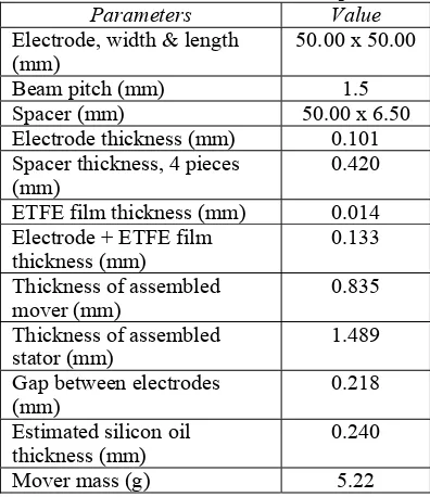
Table 1: Electrostatic actuator’s model parameters Parameters Value Electrode, width & length
(mm)
50.00 x 50.00
Beam pitch (mm) 1.5
Spacer (mm) 50.00 x 6.50
Electrode thickness (mm) 0.101 Spacer thickness, 4 pieces
(mm)
0.420 ETFE film thickness (mm) 0.014 Electrode + ETFE film
thickness (mm)
0.133 Thickness of assembled
mover (mm)
0.835 Thickness of assembled
stator (mm)
1.489 Gap between electrodes
(mm)
0.218 Estimated silicon oil
thickness (mm)
0.240
Mover mass (g) 5.22
A. DISPLACEMENT CHARACTERISTICS
Fig. 4. Influence of silicone oil viscosity on the open-loop step response using a 2kV voltage.
B. FORCE CHARACTERISTICS
In comparison with the electrostatic actuators that are maintained by precise balls, the electrostatic actuator which is only maintained by lubrication oil is greatly influenced by the electrostatic attractive force. The attractive force will change the gap and the frictional effect which consequently influences the horizontal force characteristics of the actuator. In this subsection, the force characteristics of the experimental actuator were analyzed. This action was taken to clarify the effect of the oil viscosity on maintaining the gap between the electrodes and also on the horizontal force characteristics. The effect of the attractive force depends not only on the oil viscosity and but also the applied signal pattern to the electrodes. The change of the gap influences the frictional effect in the force response, although it was not possible to measure the gap directly.
Two different approaches were utilized to assess the force characteristics, that is the force estimation from the open-loop step displacement response (referred to as the estimated force), and the force measurement using a triangular input signal whose period is 1s (referred to as the quasi-static signal force) as discussed in [7,8]. Load cell was used for the force measurement using the quasi-static signal force. The dynamic model in Fig. 3 was utilized using Eq. (1), to determine the estimated force with the least square method. The minimum voltage which can move the mover is named Vmin. The
minimum voltages were measured by applying a stepwise input voltage to the experimental actuator.
(
2 2)
min
V
V
k
F
outputted=
in−
(1)where
Foutputted = Outputted force by the actuator
k = Force gain Vin = Applied voltage
Vmin = Minimum voltage to move the mover
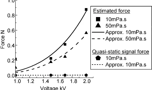
The results in Fig. 5 show the relationship between the input voltage and the thrust force with the 10mPa.s and 50mPa.s silicone oil. Two force derivation approaches are
also shown in this figure. The average force values for each condition are signified by each symbol. Each symbol indicates the average of four experimental results. Each curve was calculated with the Eq.(1) and the least square method, where each of the curves are in agreement with the Eq.(1).
The results shown in Fig. 5 depict that the 10mPa.s silicone oil leads to the production of a much greater thrust force than the 50mPa.s silicone oil for both assessed approaches. On the other hand, even though the lubricant oil with a high viscosity was expected to lower the effect of friction, no specific reduction was observed. Thus, it is clarified that low viscosity oil is better suited for the electrostatic actuator.
Results in Fig. 5 also show that the estimated force is much higher than the quasi-static signal forces. In comparison with the measured force, the displacement of the actuator immediately after the voltage input was used for the estimated force. Thus, the estimated force is least influenced by the electrostatic attractive force which increases the frictional effect between the electrodes The effect of friction is increased by the reduction in the gap attained by the attractive force between the electrodes. In conclusion, the estimated force is decided as the sensible thrust force independent of friction
Fig. 5. Relationship between the input voltage and the thrust force.
C. DRIVING SIGNALS OF THE ACTUATOR
The results in Subsection B suggest that when the period of applying the voltages between the electrodes is elongated, it vastly decreases the thrust force, although it is the voltage that generates the thrust force. Therefore, it is necessary to determine the suitable signals to drive the actuator.
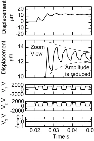
Fig. 6 show the actuator’s displacement response to a periodic rectangular input signal, as introduced in [7,8]. The periodic rectangular input signal is one of the signals that have frequency lower than the control bandwidth. This figure also shows the voltages V1 and V2 which are applied to the
Stator A and Stator B, and also voltage V3 to the mover which
is grounded as shown in Fig. 1. The voltages V1 and V2 are
2μmp-p. This result indicates that the input signal period is
long enough to increase the friction force, which limits the working range of the actuator. This leads to the conclusion that the normal signal is not suitable for the actuator because it limits the working range. Therefore, a suitable signal which is applied in a short period need to be clarified which does not influence the working range of the actuator.
D. DRIVING SIGNAL FOR FULL WORKING RANGE
As described in Subsection C, the long period for applied voltage to the actuator greatly reduces the working range. As a signal to avoid the increase of the frictional effect and to ensure the full working range, the impulse signal has been introduced in [7,8]. The time in the applied signal for the non-zero voltage is shorter than the normal signal for reducing the effect of the attractive force between the electrodes.
The impulse signal is used as the driving signal to ensure the full working range of the actuator. The sampling period of impulse signal is 1ms. The open-loop displacement characteristic using the impulse signal whose duty cycle is (1/5) and the 10mPa.s silicone oil is shown in Fig. 7. This figure depicts that its initial displacement is almost the same as the initial displacement using the normal signal (see Fig. 6); however the displacement's amplitude is kept at approximately 20μmp-p. This signifies that the impulse signal
does not influence the working range of the actuator and is useful for the full working range motion.
CONTROL PERFORMANCES
A.CONTROL SYSTEM STRUCTURE
In this section, the control performances of the electrostatic actuator are examined to show the usefulness of the actuator. Based on the PID controller, a control system was designed so that the system showed high precision positioning results. Fig. 8 shows the block diagram of the control system with the PID controller which includes a linearizer and a driving signal unit. The linearizer is used to cancel the nonlinear characteristics from the input voltage to the thrust force. The driving signal unit is added to translate the linearizer output into the impulse signal. The impulse signal whose duty cycle is (1/5) is used as the driving signal to ensure the full working range motion. The tuned PID controller parameters are Kp=25, Ki=7.5 and Kd=15.
Fig. 6. Displacement response of the actuator to a periodic rectangular input signal using silicone oil with 10mPa.s viscosity.
Fig. 7. Open-loop displacement characteristic with the impulse signal whose duty cycle (1/5) and the 10mPa.s silicone oil.
B.PERFORMANCE EVALUATION
Fig. 8: Block diagram of the control system.
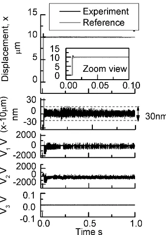
Fig. 9: Positioning result using 10μm step input under impulse signal with 0.5ms control period.
CONCLUSIONS
As a conclusion, this paper briefly provides an overview of the evaluation of a multilayer electrostatic actuator for a fine motion stage without precise balls for lubrication. To clarify the open-loop characteristics of the actuator, the actuator was examined in detail. The effects of the lubrication oil viscosity on the displacement and force characteristics were evaluated. Results of the open-loop characteristics show that low viscosity oil produces a much faster response and large thrust force. For the multilayer electrostatic actuator without precise balls, the suitable driving signals were clarified. The impulse signal was clarified as the suitable signal to ensure the full working range motion of the actuator supported by lubrication oil without precise balls. It has been verified that the impulse signal with the 0.5ms control period assisted in providing a positioning accuracy better than 15nm and with a short rise time less than 0.5ms.
REFERENCES
[1] W. J. Kim et al., “High-precision magnetic levitation stage for photolithography”, Precision Engineering, 1998; Vol. 22: pp. 66–77. [2] C. L. Chu et al., “A novel long-travel piezoelectric-driven linear
nanopositioning stage”, Precision Engineering, 2006; Vol. 30: pp. 85-95.
[3] R.M. Seugling et al., “A six-degree-of-freedom precision motion stage”, American Institute of Physics, 2002; Vol. 73: pp. 2462-2468. [4] Z. G. Zhang et al., “Electrostatically actuated robotic fish: Design and
control for high-mobility open-loop swimming”, IEEE transactions on robotic, 2008; Vol. 24: pp. 118-129.
[5] M. I. Beyaz et al., “Closed-loop control of long-range micropositioner using integrated photodiode sensors”, Sensors an Actuators A, 2009; pp. 187-194.
[6] N. Yamashita et al., “Voltage-induction type electrostatic film motor driven by two- to four-phase ac voltage and electrostatic induction”, Sensors and Actuators A, 2007; Vol. 140: pp. 239–250.
[7] Mariam Md Ghazaly, Kaiji Sato, "Open-loop Characteristics of a Multilayer Electrostatic Actuator for a Fine Motion Stage", Proceedings of the 14th International Conference on Mechatronics
Technology: 2010.
[8] Mariam Md Ghazaly, Kaiji Sato, "Control Performances of a Fine Motion Stage using a Multilayer Electrostatic Actuator without Precise Balls for Lubrication", Proceedings of the 14th International