Open-loop Characteristics of a Multilayer Electrostatic Actuator for a Fine
Motion Stage
Mariam Md Ghazaly*, Kaiji Sato
Interdisciplinary Graduate School of Science and Engineering, Tokyo Institute of Technology,
4259-G2-17 Nagatsuta Midori-ku, Yokohama 226-8502, JAPAN
*Email: [email protected]
Abstract
This paper outlines the open-loop characteristics of a multilayer electrostatic actuator utilized for a fine motion stage without precise balls. The research was undertaken in order to envisage a practical and simple multilayer electrostatic actuator that produces high precision motion and sufficient force for a fine motion stage. For this purpose, a two-layer electrostatic actuator was developed and examined. Lubrication oils are used as lubricants in order to obtain low friction by maintaining the gaps between the stator and mover layers without precise balls for simplicity and easy maintenance. Each layer of the electrostatic actuator has one electrode, which consists of several beams. This paper examines the effects of the lubrication oil viscosity on the displacement and force characteristics in order to clarify the suitable lubrication oil utilized on the actuator. It was found that when using low viscosity lubrication oil, a shorter response time and greater thrust force was observed. Secondly, high dielectric fillers were added to the lubrication oil, and the displacement and force characteristics were then evaluated. The results show that addition of the fillers assisted in producing a shorter response time and a thrust force which was significantly larger. Lastly, the resultant effects of the driving signals on the motion characteristics were evaluated, which concluded with the discussion in the signal selection on demand.
1.
Introduction
Typically, fine stages are often utilized in semiconductor manufacturing systems, machine tools and scanning probe microscope systems which are often desired to have high positioning accuracy in a short positioning time [1]. The fine stages are also desired to generate low heat, have a simple design and be easy to maintain. To date, both piezoelectric actuators [2] and electromagnetic actuators [1] are typically used for those fine stages. However, the main drawback being that the piezoelectric actuators are of a complex structure as they require hinges in order to allow a multiple degree of freedom for the fine stages. Additionally, these hinges become vibration elements. On the other hand, the
electromagnetic actuators produce a greater thrust force and enable a multiple degrees of freedom motion for the fine stages without utilizing hinges. However, the electromagnetic actuators generate high heat [4], which may deform products on the stages and the fine stages themselves.
In this research, the introduction of an electrostatic actuator utilized for a fine stage is discussed. The heat generated by the electrostatic actuators is essentially much lower than that of the electromagnetic actuators. A further benefit is that the electrostatic actuators do not require hinges, whereas the piezoelectric actuator does.
Several types of electrostatic actuators i.e. varying capacitance motors have been developed to date [5,6]. Others include induction motors [7]. For these actuators, precise balls are utilized to reduce the frictional effect and also assist in the maintenance of the gap between the electrodes [5,7]. Ghodssi et al. [6] designed and developed a flexible capacitance motor with the use of micro ball bearings in order to maintain a precise gap between the mover and stator layers. These actuators show good performances, however the drawback with these methods was that these precise balls typically are more expensive and the system becomes more complex. Industrial utilized systems should be simple and easily maintained as well as cost effective.
The purpose of this research is to envisage a multilayer electrostatic actuator for a precise fine motion stage which has a simple structure, is easy to maintain and cost effective. To realize this, a two-layer electrostatic actuator was developed and examined. In order to reduce the frictional effect and to assist in the maintenance of the gap between the electrodes, lubrication oil was used as a lubricant, but without precise balls.
2. Structure of the electrostatic actuator
The type of electrostatic actuator in this research is the variable capacitance motor that is useful for a short working range motion. A general schematic of the actuator’s structure can be found in Fig. 1. The actuator consists of a pair of electrodes that have several parallel beams. As the actuator is of a simplified structure, it is easy to manufacture.
Ground Voltage Electrode stator Electrode Mover
p: Beam pitch
Driving direction Electrode beam Width Leng th Ground Voltage Electrode stator Electrode Mover
p: Beam pitch
Driving direction Electrode beam Width Leng th
Fig. 1. General schematic of the electrostatic actuator.
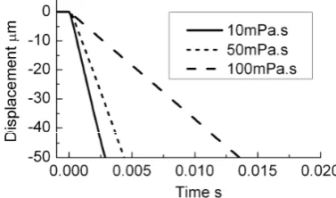
In this paper, the electrostatic actuator was two layered. Fig. 2 shows the side view of the electrostatic actuator that was designed for this research. The figure shows the mover and stator layers as being stacked together. Ethylene thetrafluoroethylene (ETFE) films are wrapped around the electrodes as isolation films. The ETFE film was adopted so that the contact condition between the electrode layers reduces the friction force. To realize a bi-directional motion, voltages namely V1 and V2 are alternately applied to the Stator A and Stator B, whilst the mover is set to zero (grounded). To keep the frictional effect low and to maintain the gap between each electrode, lubrication oil and dielectric film are used. The lubrication oil is utilized instead of the precise balls to allow a simple structure for easy maintenance of the actuator. Table 1 shows the list of the parameters used for the experimental actuator and Fig. 3 shows the dynamic model of the actuator.
The experimental setup is shown in Fig. 4. The setup consists of a capacitance displacement sensor, high voltage amplifiers and a digital signal processing system. This setup is used to measure the displacement characteristics. A load cell is replaced with the capacitance displacement sensor to enable the measurement of force characteristics.
Stator
Mover
ETFE
Film
Electrode
Spacer
(phosphorus
bronze)
Spacer
(polymer)
Lubrication
oil
Plastic
screw
Stator A
(V1)
Stator B
(V2)
Stator
Mover
ETFE
Film
Electrode
Spacer
(phosphorus
bronze)
Spacer
(polymer)
Lubrication
oil
Plastic
screw
Stator A
(V1)
Stator B
(V2)
Fig. 2. Side view of the two-layer electrostatic actuator
3. Open-loop characteristics
3.1. Effect of lubrication oils viscosity
In this paper, silicone oils are used as lubricant. Several silicone oils are used with different viscosity to clarify their effects on the displacement and force characteristics. High response is often important for fine stages and influenced by the oil viscosity. It is anticipated that a higher viscosity silicone oil has a higher ability to be maintained inside the gaps thus reducing the frictional effect. Also, it is expected that a lower viscosity silicone oil would be able to provide low damping characteristics in the traveling direction for high response.
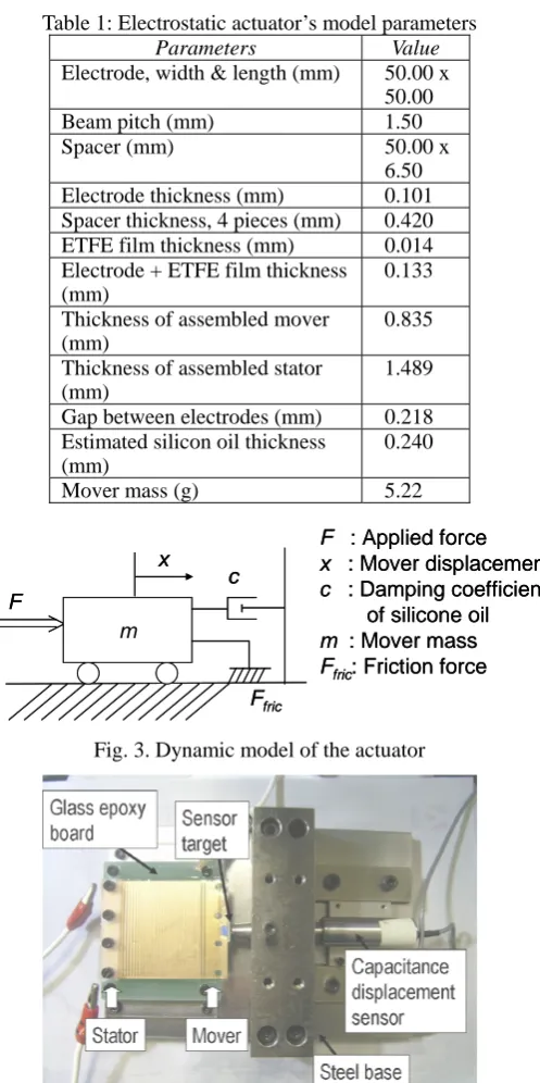
Table 1: Electrostatic actuator’s model parameters
Parameters Value
Electrode, width & length (mm) 50.00 x 50.00
Beam pitch (mm) 1.50
Spacer (mm) 50.00 x
6.50 Electrode thickness (mm) 0.101 Spacer thickness, 4 pieces (mm) 0.420 ETFE film thickness (mm) 0.014 Electrode + ETFE film thickness
(mm)
0.133
Thickness of assembled mover (mm)
0.835
Thickness of assembled stator (mm)
1.489
Gap between electrodes (mm) 0.218 Estimated silicon oil thickness
(mm)
0.240
Mover mass (g) 5.22
m
c F
x
Ffric
F : Applied force x : Mover displacement c : Damping coefficient
of silicone oil
m : Mover mass Ffric: Friction force
m
c F
x
Ffric
F : Applied force x : Mover displacement c : Damping coefficient
of silicone oil
m : Mover mass Ffric: Friction force
Fig. 3. Dynamic model of the actuator
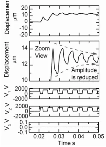
Fig. 5 illustrates the influence of the silicone oil viscosity on the open-loop step responses. The dielectric constant of the 10mPa.s, 50mPa.s and 100mPa.s silicone oils is 2.65, 2.72 and 2.74 respectively. For each of the response, similar experiments were conducted 20 times. Each line represents the typical displacement response for each silicone oil when the actuator was applied with a 2kV voltage. In this paper, the response time refers to the 50μm displacement. When comparing the 10mPa.s, 50mPa.s and 100mPa.s silicone oils, the 10mPa.s exhibits the shortest response time, which shows that the low viscosity oil is better suited for higher response as shown in Fig. 5.
The force characteristics of the experimental actuator were also analyzed. This action was taken to clarify the effect of the oil viscosity on maintaining the gap between the electrodes. The change of the gap influences the frictional effect in the force response, although it was not possible to measure the gap directly. Three different approaches were utilized to assess the force characteristics, that is the force estimation from the open-loop step displacement response (referred to as the estimated force), the force measurement using a step input signal (referred to as the step signal force) and the force measurement using a triangular input signal whose period is 1s (referred to as the quasi-static signal force). Load cell was used for the force measurement using the step signal force and quasi-static signal force. The dynamic model in Fig. 3 was utilized to determine the estimated force with the least square method.
The results in Fig. 6 show the relationship between the input voltage and the thrust force with the 10mPa.s and 50mPa.s silicone oil. Three force derivation approaches are also shown in this figure. The average force values for each condition are signified by each symbol. Each symbol indicates the average of four experimental results. Each curve was calculated with the Eq.(1) and the least square method, where each of the curves are in agreement with the Eq.(1). From Eq. (1), Vmin indicates the minimum voltage which can shift the
mover. To measure the minimum voltage, a stepwise input voltage was applied to the actuator.
(
2 2)
min
V
V
k
F
outputted=
in−
(1)where,
Foutputted = Outputted force by the actuator
k = Force gain Vin = Applied voltage
Vmin = Minimum voltage to move the mover
The results shown in Fig. 6 depict that the 10mPa.s silicone oil leads to the production of a much greater thrust force than the 50mPa.s silicone oil. On the other hand, even though the lubricant oil with a high viscosity was expected to lower the effect of friction, no specific reduction was observed. Thus, it is clarified that low viscosity oil is better suited for the electrostatic actuator.
Results in Fig. 6 also show that the estimated force is much higher than the other forces. The estimated force calculation is taken from the results which were measured in a shorter time and which is least influenced by the electrostatic attractive force between electrodes.
The effect of friction is increased by the reduction in the gap attained by the attractive force between the electrodes. In conclusion, the estimated force is decided as the realistic thrust force independent of friction.
Fig.5. Influence of silicone oils viscosity on the open-loop step responses using a 2kV voltage.
Fig. 6. Relationship between the input voltage and the thrust force with the 10mPa.s and 50mPa.s silicone oils.
3.2. Effect of high dielectric fillers
The addition of high dielectric fillers to the silicone oil increases the apparent dielectric constant between electrodes, which is expected to increase the produced thrust force. Barium titanate (BT-HP9DX produced by KCM Corp. Japan) is used as the high dielectric fillers with a dielectric constant larger than 1000. The median particle size (D50) for the fillers is 0.15μm. Fig. 7 illustrates the comparison of the added fillers to the 10mPa.s silicone oil on the displacement characteristics. The ratio of silicone oil and fillers that was used for the mixed 10mPa.s silicone oil is (1:1) ratio. For the mixed 10mPa.s (1:1) ratio oil, the dielectric constant is 3.63 (calculated with Eq. (1) based on the estimated force) and its viscosity is 23mPa.s (estimated from its damping coefficient). Each line represents the typical displacement response for each lubrication oil. Fig. 7 provides evidence that the high dielectric fillers added to the 10mPa.s silicone oil shorten the response times of the actuator by 24.1%.
experimental results. The curves are the approximation based on Eq.(1). Fig. 8 shows that the lubrication oil with the high dielectric fillers assists in increasing the produced thrust force by 62% for the 10mPa.s silicone oil. Thus, this provides evidence that the fillers are useful in increasing the thrust force of the actuator.
Fig. 7. Effect of adding fillers to the 10mPa.s silicone oil on the displacement characteristics using a 2kV voltage.
Fig. 8. Effect of the fillers in the 10mPa.s silicone oil on the estimated force.
4. Driving signals of the actuator
4.1 Basic dynamic of displacement
characteristics
The results in Section 3 show that when the time applying the voltages between the electrodes is elongated, it vastly decreases the thrust force, although it is the voltage that generates the thrust force. Therefore, it is necessary to determine the suitable signals to drive the actuator.
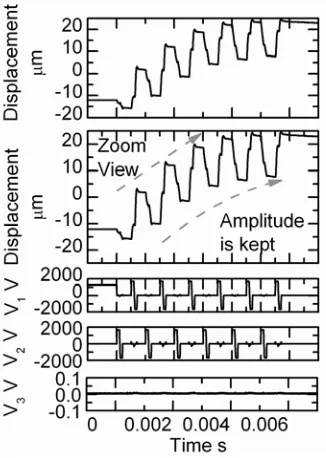
Fig. 9 show the actuator’s displacement response to a periodic rectangular input signal. This figure also shows the voltages V1 and V2 which are applied to the Stator A and Stator B, and also voltage V3 to the mover which is grounded as shown in Fig. 2. The voltages V1 and V2 are out of phase by
π.
This input signal is referred to as the normal signal in this paper. From Fig. 9, it can be seen that the initial displacement is relatively large. However, the amplitude of the displacement is reduced to roughly around 2μmp-p. This result indicates that the input signal period is sufficient enough toincrease the friction force, which limits the working range of the actuator. In this paper, the limited working range is defined as the fine working range. This leads to the conclusion that the normal signal is useful only for the fine working range. However, the advantage is that the holding force by the actuator is large. In order to benefit from this characteristic, the normal signal with the addition of a holding signal is evaluated. The combination of the normal signal and the holding signal is referred to as the fine driving mode signal which is use for the fine driving mode. The holding signal is a constant 1kV voltage always applied to the actuator. By implementing this mode, the electrostatic actuator is able to hold the controlled object effectively by the friction between the electrodes. Fig. 10 shows the displacement characteristic under the fine driving mode. This figure illustrates that the displacement of 0.12μmp-p is produced by the electrostatic actuator under a holding signal of 1kV. However, the displacement is shifted upward. This is because the frictional effect depends on the motion direction of the actuator.
Fig. 9. Displacement response of the actuator to a
periodic rectangular input signal using silicone oil with 10mPa.s viscosity.
4.2
Driving signal for full working range
To clarify the influence of the impulse signal’s duty cycle on the displacement characteristic, experiments were conducted with the impulse signal whose duty cycle is (1/2.5) and the 10mPa.s silicone oil. Fig. 12 shows the displacement’s amplitude is not kept with the impulse signal whose duty cycle is (1/2.5), which means that the signal whose duty cycle is (1/5) is better suited for the wide working range.
Fig. 10. Displacement characteristic under the fine driving mode.
Fig. 11. Open-loop displacement characteristics using the impulse signal whose duty cycle is (1/5) and the 10mPa.s silicone oil.
5. Conclusion
In summary, the characteristics of the two-layer electrostatic actuators have been outlined. In order to reduce the frictional effect, only lubrication oil was utilized, which would assist in reducing the frictional effect and maintaining the gap. To clarify the open-loop characteristics of the actuator, the actuator was examined in detail. The effects of the lubrication oil viscosity on the displacement and force characteristics were evaluated. Results of the open-loop characteristics show that low viscosity oil produces a much faster response and large thrust force. The effects of the high dielectric fillers on the displacement and force characteristics were also examined. The addition of high dielectric fillers to the lubrication oil shortens the response time of the actuator and generates larger thrust force. For the multilayer electrostatic actuator without precise balls, the suitable driving signals were clarified. When the working range which is shorter than 0.12μmp-p is desired, the normal signal is useful. With the aid of the holding signal, this enables the actuator to hold the mover with a large holding force in the fine range motion. Additionally, when a wider working range is desired, the impulse signal is useful. The impulse signal enables the working range wider than 20μmp-p.
Fig. 12. Open-loop displacement characteristics using the impulse signal whose duty cycle is (1/2.5) and the 10mPa.s silicone oil.
References
[1] Won-Jong Kim and David L. Trumper, High-precision magnetic levitation stage for photolithography, Precision Engineering, Vol. 22, 1998, pp. 66–77.
[3] R.M. Seugling, T. LeBrun, S.T.. Smith, L.P. Howard, A six-degree-of-freedom precision motion stage, American Institute of Physics, Vol. 73, 2002, pp. 2462-2468.
[4] Shih-Kang Kuo and Chia-Hsiang Menq, Modeling and control of a six-Axis precision motion control stage, IEEE/ASME Transactions on Mechatronics, Vol. 10, no. 1, 2005, pp. 50-59.
[5] Zu Guang Zhang, Norio Yamashita, Masahiko Gondo, Akio Yamamoto and Toshiro Higuchi, Electrostatically actuated robotic fish: Design and control for high-mobility open-loop swimming, IEEE transactions on robotic, Vol. 24, No. 1, 2008, pp. 118-129.
[6] Mustafa ilker Beyaz, Matthew Mc Carthy, Nima Ghalichechian, Reza Ghodssi, Closed-loop control of long-range micropositioner using integrated photodiode sensors, Sensors an Actuators A, 2009, pp. 187-194.