PROGRAMMABLE LOGIC CONTROL (PLC)
APPLICATION FOR STAMPING OPERATION
MOHD JAZRIN BIN SHAMSUL BAHRIN
UNIVERSITI TEKNIKAL MALAYSIA MELAKA
PROGRAMMABLE LOGIC CONTROL (PLC) APPLICATION
FOR STAMPING OPERATION
This report submitted in accordance with requirement of the Universiti Teknikal Malaysia Melaka (UTeM) for the Bachelor Degree of Manufacturing Engineering
(Robotic and Automation) with Honors.
by
MOHD JAZRIN BIN SHAMSUL BAHRIN
DECLARATION
I hereby, declared this report entitled “Programmable Logic Control (PLC) Application for Stamping Operation” is the results of my research except as cited in references.
Signature :
APPROVAL
This report is submitted to the Faculty of Manufacturing Engineering of UTeM as a partial fulfillment of the requirements for the degree of Bachelor of Manufacturing Engineering (Robotic and Automation) with Honors. The member of supervisor committee is as follow:
ABSTRACT
This project is conducted in order to design a new ladder diagram for the application of a stamping process. This project is done to simulate and demonstrate the process sequence
of an automatic rubber stamping. A physical simulation is done using a rubber stamping kit that comes with a Siemens programmable logic controller. This programming software’s is been selected because it has its own capabilities and designated symbol. By determining the process sequence and input output characteristics, a ladder diagram
ABSTRAK
Projek ini dijalankan untuk mencipta litar tetangga sebagai aturcara bagi penggunaan proses mencetak. Litar tersebut digunakan untuk tujuan simulasi dan demonstrasi bagi
keseluruhan process dalam sistem pencetak getah automatik. ”Siemens programmable logic controller” yang didatangkan bersama perkakasan pencetak getah telah digunakan untuk simulasi fizikal. Perisian ini dipilih kerana ia mempunyai keupayaan dan simbol tersendiri. Apabila aturan proses dan sifat kemasukan dan keluaran dikenalpasti, litar
ACKNOWLEDGEMENT
Alhamdulillah, thanks to Allah the Almighty for His will, I have been given the chance
to be able to complete my Projek Sarjana Muda 1 (PSM 1) report from the very first word till the end point within the specified period of time. First of all, I would like to take this opportunity to express my thankfulness and appreciation to my PSM supervisor, Mr. Lokman bin Abdullah for his supervision, comments and guidance in order to make sure I can gain as much experience and knowledge to complete my PSM 1
report. I also like to thank Mr. Mohd. Isa and Mr. Ali Sham for their full fledge support in completing my project. I also want to thank to my fellow course mate from BMFA for the input sharing and all those comments for my PSM report. I would also like to express special regards to my family members for their priceless support,
TABLE OF CONTENT
2.1 History of Programmable Logic Controller (PLC) 5
2.1.1 Programmable Logic Controller (PLC) 6
2.2 PLC Components 9
2.2.1 Power Supply Unit (PSU) of PLC Controller 9
2.2.2 Central Processing Unit (CPU) of PLC Controller 11
2.2.3 Input and Output Module in PLC controller 11
2.4.2 Function Block Diagram (FBD) 20
2.4.3 Statement List (STL) 21
2.4.4 Sequential Flow Chart (SFC) 22
2.5 PLC Programming Instructions 24
2.5.1 Functions of Contacts in PLC 24
2.5.2 Functions of Coil in PLC 26
2.5.3 Functions of Counter in PLC 28
2.5.4 Functions of Timer in PLC 31
3. PROJECT METHODOLOGY 34
3.1 PSM Project Planning 34
3.2 Introductory Phase 38
3.3 Finding Related Information and Literature 38
3.4 Designing Diagram for Controller and Hardware Component 39 3.4.1 Comparing Designs of Hardware Component Diagram 40
3.4.2 Comparing Designs of PLC Ladder Diagram 42
3.5 Integrating Controller and Equipments 45
3.6 Testing Controller Connections with Equipments 47
3.7 Analyzing System Sequence and Ladder Diagram 48 3.8 Improving Ladder Diagram and System Sequence 48
4. DESIGN AND DEVELOPMENT 51
4.1 Stamping Machine 51
4.2 Control Panel 54
4.3 Circuit Design 57
4.4 Programmable Logic Control Program 60
5. RESULT AND DISCUSSION 67
5.1 Ladder Logic Diagram 67
5.1.2 Function Block 1 (Operation Sequence) 69 5.1.3 Function Block 2 (Error or Emergency Function) 77
5.1.4 Function Block 3 (Reset Function) 79
5.2 Low Level Language 81
5.2.1 Function Block 1 (Operation Sequence) 81
5.2.2 Function Block 2 (Error Function) 84
5.2.3 Function Block 3 (Reset Function) 85
5.3 Electro-Pneumatic Control Diagram 85
5.4 Truth Table 88
5.5 Boolean Equation for Automated Stamping Machine 88
5.6 Network Logic Diagram 89
5.7 Time Vs Air Flow Rate Analysis 89
5.8 Pneumatic System Sequence Analysis 91
6. CONCLUSION AND SUGGESTIONS 95
6.1 Conclusion 95
6.2 Suggestions for Future Work 95
LIST OF TABLES
3.1 PSM 1 Gantt Chart 36
3.2 PSM 1 and 2 Gantt Chart 37
5.1 Function Block 1 Mnemonic Code (Network 1 to 8) 81
5.2 Function Block 1 Mnemonic Code (Network 9 to 19) 82 5.3 Function Block 1 Mnemonic Code (Network 20 to 27) 83
5.4 Function Block 2 Mnemonic Code 84
5.5 Function Block 3 Mnemonic Code 85
5.6 Truth Table for Automated Stamping Machine 88
5.7 Result of Time Vs Air Flow Rate 90
5.8 Actuator Motion State 92
LIST OF FIGURES
1.1 Rubber Stamping 3
2.1 Overview of PLC 11
2.2 Example of Out Module Connection 13
2.3 Example of Input Module Connection 13
2.4 Memory of Program Files 14
2.5 Memory of Data 15
2.6 5/2 Way DCV Initial Condition. 17
2.7 5/2 Way DCV Energized Condition. 17
2.8 Example of Ladder Diagram Programming 19
2.9 Example of FBD Programming 20
2.10 Example of STL Programming 21
2.27 Symbol of Off Delay Timer 33
3.1 PSM Project Flow Chart 35
3.2 Pneumatic Design 1 40
3.3 Pneumatic Design 2 41
3.4 First PLC Ladder Diagram Design using Automation Studio 43 3.5a Second Design using Omron CX-Programmer (Rung 1) 44
3.5b Second Design using Omron CX-Programmer (Rung 2) 45
3.6 Integrating with Omron PLC 46
4.3 Automated Stamping Machine (Side View) 52
4.4 Paper Feed and Ink Pad Actuators 53
4.5 Rubber Stamp Actuator 53
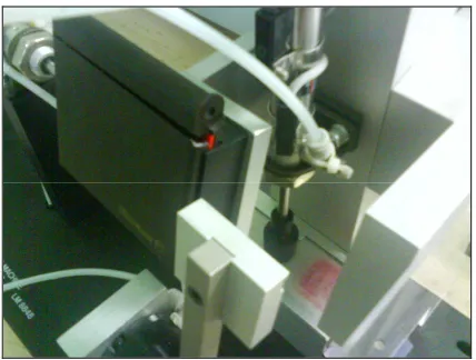
4.6 Siemens S7-300 Controller with IO Modules 54
4.7 Model of Top and Bottom Control Panel 54
4.8 Model of Complete Control Panel (Isometric View) 55
4.9 Actual Completed Control Panel 55
4.10 Top Control Panel Wiring 56
4.11 Bottom Control Panel Wiring 56
4.12 Voltage Converter 57
4.13 Input and Output Module Wiring Schematic 58
4.14 Control Panel Wiring Schematic 59
4.15 Controller Model Selection 60
4.16 Hardware Placement for Controller 61
4.17 Hardware Configuration for Controller 61
4.19 Memory Requirements for Each Block in Byte 62
4.20 Input and Output Addresses 63
4.21 Internal Output Declaration for Function Block 1 64 4.22 Internal Output Declaration for Function Block 2 65 4.23 Internal Output Declaration for Function Block 2 (cont) 66 4.24 Internal Output Declaration for Function Block 3 66
5.1 Organization Block for Automated Stamping Machine 68
5.2 Function Block LAD 1 Network 1 70
5.15 Electro-Pneumatic Schematic 87
5.16 Network Logic Diagram for Automated Stamping Machine 89
5.17 Graph of Air Flow Rate Vs Time 90
CHAPTER 1
INTRODUCTION
This chapter will cover the introduction of final year project entitled Programmable Logic Control (PLC) Application for Stamping Machine. In the beginning of this
chapter, it will briefly explain about the project background, fundamentals of PLC and its components. This chapter will also describe about the process of rubber stamping that have been chosen in this project. This chapter will also emphasize the problem statement, objective and scope of study that are stated in this chapter as guidance throughout this project at the end of the chapter.
1.1 Project Background
This project is basically a Programmable Logical Controller (PLC) based control
system. The project is done by integrating PLC with a pneumatic driven stamping machine. This machine will run on several step of process that is paper feed, stamping and cutting to length. The processes will be driven by pneumatic cylinders. All the cylinders are incorporated by solenoid valves thus can be controlled and signaled by a PLC. The cylinders uses 5/2 way Directional Control Valves (DCV) that is ventilated at
The purpose of this project is to generate the correct sequence of events for a stamping machine by designing PLC ladder diagram using Siemens or Omron program.
Simulation of the stamping process will be done physically on a stamping kit.
Rubber stamping is also called stamping. It is a craft in which some type of ink made of dye or pigment is applied to an image or pattern that has been carved, molded, laser
engraved or vulcanized, onto a sheet of rubber. The rubber is often mounted onto a more stable object such as a wood, brick or an acrylic block to produce a more solid instrument. The ink coated rubberstamp is then pressed onto any type of medium such that the colored image has now been transferred to the medium. The medium is generally some type of fabric or paper. High volume batik uses liquid wax instead of ink
on a metal stamp.
Commercially available rubber stamps fall into three categories that are stamps for use in the office, stamps used for decorating objects or those used as children's toys. Rubber
stamps for business are custom-made, showing an address, a corporate logo or something similar, or they are bought ready-made. They often have movable parts that allow the user to adjust the date or the wording of the stamp. Art stamps have become fashionable and mostly regarded as children's toys. They are available in many intricate
Figure 1.1: Rubber Stamping
1.2 Problem Statement
Stamping is a huge process in the industry. However it depends on the requirement of
stamping processes in order to produce the desired output. Stamping processes could be designed in any desired sequences and layout. The design on layout is based on the station needed to complete the stamping process. The design of the stamping sequence also based on the components used such as input components and output component. All the designs are integrated in a form of a computer language called ladder diagram that is
used as control sequences to the PLC. Multiple stamping sequences occupy long and excessive PLC instructions. The physical components of a multiple stamping sequence are integrated into the input module and the output module of the PLC based on the number of input output (IO) needed. The instructions are also hard to interpret if the
1.3 Objective
This project will focus only on one goal that is to design a PLC Ladder Diagram for the purpose of Stamping Operation
1.4 Scope of Project
a) To learn and design a PLC Ladder Diagram using Simatic STEP 7 and CX Programming.
b) To learn and integrated PLC programming and PLC components with Stamping Kit.
CHAPTER 2
LITERATURE REVIEW
In this chapter, it will cover on the fundamentals of PLC applications in the area of designing a ladder diagram. It will emphasize on symbol functions that are used in PLC programs. These reviews will give the insight into important principle and processes of
controller thus help in the designing of the ladder diagram in order to be more efficient.
2.1 History of Programmable Logic Controller (PLC)
According to Bolton (2004), in the 1960 and 1970s, electromechanical relay, timers, counters and sequencers were standard. Many control panels contained hundreds of
these electromechanically devices. The primary negativity aspect of mechanical control was that the reliability was low thus keeping these panel operating were extremely high. The PLC was invented in response to the needs of the American automotive industry. Before the PLC, control, sequencing, and safety interlock logic for manufacturing automobiles was accomplished using relays, timers and dedicated closed-loop
controllers.
The auto industries complained that the cost of purchasing and changing a single relay is highly cost. The second factor involved time, expenses and labor required when a
The winning proposal came from Bedford Associates that designated the 084 product called Modicon, which stood for Modular Digital Controller.
One of the people who worked on that project was Dick Morley, who is considered to be the "father" of the PLC. The unit was retired after nearly twenty years of uninterrupted service. According to Jansen (1996) PLCs are used in many different industries and machines such as packaging and semiconductor machines. Well known PLC brands are
Siemens, Allen-Bradley, ABB, Mitsubishi, Omron, Schneider Electric and General Electric. High speed manufacturing such as automotive industry requires reliable control devices that were smaller, consumed less power, featured fast switching and were quickly and easily changeable. It also must withstand the harsh industrial environment.
2.1.1 Programmable Logic Controller (PLC)
A programmable logic controller is a digitally operating electronic apparatus which uses a programmable memory for the internal storage of instructions for implementing specific functions, such as logic, sequencing, timing, counting and arithmetic, to control
through digital or analog input and output, various types of machines or process. PLC is also referred to as programmable controllers that are used in commercial and industrial applications. It consists of input modules, a Central Processing Unit (CPU), and output modules. The PLC accepts inputs from switches and sensors that measures or senses from the system. An input module accepts a variety of digital or analog signals from
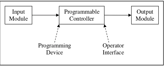
Figure 2.1: Overview of PLC.
Basic hardware components of a PLC system consist of central processor unit (CPU),
input and output modules, power supply unit and programming device. The central processor unit (CPU) is a microprocessor system that contains the system memory and is the PLC decision making unit. The CPU monitors the inputs and makes decisions based on instructions held in the program memory.
The CPU performs relay, counting, timing, data comparison, and sequential operations. The size and type of CPU will determine the programming functions available, size of the application logic available, amount of memory available, and processing speed.
Many types of inputs and outputs could be connected to a PLC, and they can all be divided into analog and digital. Inputs carry signals from the process into the controller, they can be input switches, pressure sensors, operator inputs.
A discrete input also referred to as a digital input, is an input that operate due to a discrete or binary change either in an ON or OFF condition. Pushbuttons, toggle switches, limit switches and proximity switches are examples of discrete sensors. However, an analog input is an input signal that has a continuous signal that changes continuously over a variable range. Typical examples of analog input are pressure,
temperature and potentiometer. A discrete output is an output that is either in an ON or OFF condition. Solenoids, contactor coils, and lamps are examples of actuator devices connected to discrete outputs. Discrete outputs may also be referred to as digital outputs.
The PLC is programmed using a specialty programmer or software on a computer that can load and change the logic inside. Most modern PLC is programmed using software
on a PC or laptop computer. Older systems used a custom programming device. Programming device is used to enter the required program into the memory of the processor. The program is developed in the programming device and then transferred to the memory unit of the PLC. Software is required in order to tell the PLC what instructions it must follow. Software is typically PLC specific because a software
package for one PLC, or one family of PLC, such as the S7 family, would not be useful on other brands of PLC. While there are be as many advantages about PLC. These controllers help to make the best possible use of:
a) Gain complete control of manufacturing process.
g) Lower the cost of quality, rework and scrap. h) Offer greater product variety.
i) Quickly changeover from one product to another
2.2 PLC Components
Control components are used in a wide variety of applications with varying degrees of complexity. According to Mohammad Rashid (2004), control circuits used in commercial and industrial applications tend to be more complex than this simple circuit
and employ a broader variety of components. However, the function of these circuits is often the same, to turn something on and off. In some cases, manual control is used. More often, automatic control circuits or circuits that combine manual and automatic control are used. The interaction of these components is dependent only on how they are
wired to each other. This is sometimes referred to as hard-wired logic. Increasingly, however, these components are wired to a control system, such as a programmable logic controller or variable speed drive. In such cases, the interaction of the circuit components is dependent both on wiring and the software stored in the controller. There
are many choices of PLC in the market thus making it confusing to choose. This problem is overcome by restricting the selections by defining the feature that are required in a particular application such as number of input, number of output, scan time, data memory space, output drive option, programming tool and communication protocol.
2.2.1Power Supply Unit (PSU) of PLC Controller
Power supply is a reference to a source of electrical power. A device or system that
supplies electrical or other types of energy to an output load or group of loads is called a power supply unit or PSU. The term "power supply" is sometimes restricted to those devices that convert some other form of energy into electricity. A more accurate term for devices that convert one form of electric power into another form (such as transformers and linear regulators) is power converter. The most common conversion is AC-DC. This
According to Dunning (2002), the term is most commonly applied to electrical energy supplies, less often to mechanical ones, and rarely to others. The power supply module
produces the voltage for the electronic devices of the automation equipment from network voltage. The height of this voltage amounts to 24 V. Voltages for sensor signals, actuators and warning lights, which lie over 24 V, supply additional voltage for power supply units and/or control transformers. An AC powered linear power supply usually uses a transformer to convert the voltage from the wall outlet (mains) to a
different, usually a lower voltage. If it is used to produce DC, a rectifier is used. A capacitor is used to smooth the pulsating current from the rectifier.
According to Kalsi (2004), the voltage produced by an unregulated power supply will vary depending on the load and on variations in the AC supply voltage. For critical
electronics applications a linear regulator will be used to stabilize and adjust the voltage. This regulator will also greatly reduce the ripple and noise in the output DC current. Linear regulators often provide current limiting, protecting the power supply and attached circuit from over current. The power supply specified depends upon the
manufactures PLC being utilizes in the application.
A power supply capable of delivering all required power for the system is furnished as apart of the processor module. If the power supply is a separate module, it must be
capable of delivering a current greater then the sum of all the current needed by the other modules. Systems with the power supply inside the CPU module, there may be some modules in the system that requires excessive power not available from the processor because of either voltage or current requirements that can only be achieved through the additional of a second power source. This is generally true if analog or external