1 2
3
UNIVERSITI TEKNIKAL MALAYSIA MELAKA 4
FAKULTI KEJURUTERAAN ELEKTRIK 5
6 7
PROJEK SARJANA MUDA 8
( PSM 2) 9
BEKU 4983 10
11 12 13
DESIGN AND DEVELOPMENT OF AN EMBEDDED 14
CONTROLLER FOR ROBOTIC APPLICATION 15
16 17
LIM WEE TECK 18
19
5 6 7 8 9
“I hereby declared that I have read through this report and found that it has 10
comply the partial fulfillment for awarding the degree of Bachelor of 11
Electrical Engineering ( Control, Instrumentation and Automation )” 12
13 14
Signature : 15
Supervisor’s Name :En. MOHD SHAHRIEEL Bin MOHD ARAS 16
Date :7 May 2008
DESIGN AND DEVELOPMENT OF AN EMBEDDED CONTROLLER FOR ROBOTIC APPLICATION.
LIM WEE TECK
This Report Is Submitted In Partial Fulfillment Of Requirements For The Degree of Bachelor In Electrical Engineering
(Control, Instrumentation and Automation)
Fakulti Kejuruteraan Elektrik
Universiti Teknikal Malaysia Melaka
“I hereby declared that this report is a result of my own work except for the excerpts that have been cited clearly in the references.”
Signature :
iii
To my dearly loved father and mother
ACKNOWLEDGEMENTS
I wish to thank my project supervisor, En Mohd Shahrieel Bin Mohd Aras for his guidance and teachings. And also would like to thank both the panels for their guidance.
I would also wish to extend my gratitude to my parents for their support and their understanding.
v
ABSTRAK
ABSTRACT
vii
CONTENTS
CHAPTER TITLE PAGE
SUPERVISOR’S VERIFICATION
PROJECT TITLE
AUTHENTICATION ii
DEDICATIONS iii
ACKNOWLEDGEMENT iv
ABSTRACT v
CONTENTS vii
LIST OF TABLES x
LIST OF FIGURES xi
LIST OF APPENDIX xiv
LIST OF SYMBOLS AND TERMS xv
1 INTRODUCTION
1.1 Background 1
1.2 Problem Statement 2
1.3 Project Objective 2
1.4 Project Scope 2
2.1 Introduction 4
2.2 Microcontrollers 5
2.3 Microcontrollers from Microchip 7 2.4 Why Use PIC16F877A Microcontroller 8
2.5 877-TB Project Kit 9
2.6 RHINO Robot XR-3 10
3 THEORY AND DESIGN
3.1 PIC16F877A 12
3.2 Circuit Diagram 16
3.2.1 Main Controller Circuit 16 3.2.2 Input and Output Circuit 17
3.3 MikroC 19
3.4 Servomotor 20
3.5 Robotic Arm Design 22
4 RESULTS
4.1 PCB Controller Board 25
4.1.1 Main PCB Controller Board 25
4.1.2 Additional Board 28
4.2 Controller Board 31
4.2.1 Connection Description 33
4.3 Hardware 35
4.3.1 Base 36
ix
4.3.3 Gripper 40
4.3.4 Control Box 41
4.4 Software 42
4.4.1 Programming Language 42 4.4.2 Simulation Software 42 4.4.3 Downloader Program 42
5 ANALYSIS
5.1 Experiment 1 44
5.2 Experiment 2 47
5.3 Experiment 3 50
6 CONCLUSION & FUTURE PLANNING
6.0 Conclusion 57
6.1 Future Planning 58
REFERENCE 60
LIST OF TABLES
TABLE TITLE PAGE
2.0 Various brand of Microcontroller 6
2.1 Specifications of Rhino Robot 11
xi
LIST OF FIGURES
FIGURE TITLE PAGE
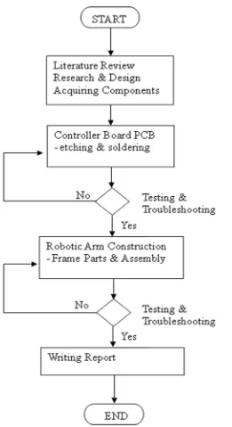
1.0 Methodology Flow Chart 3
2.0 Elements in Microcontroller 5
2.1 PIC from Microchip 7
2.2 877-TB PIC Board 9
2.3 RHINO Robot 10
3.0 PIC16F877A 15
3.1 Controller Circuit Diagram 16
3.2 Input Connections to Push Button 17
Circuit Diagrams
3.3 Output Connections to Srevo Motor 17
Circuit Diagrams
3.4 I/O connections to PIC 1 (Primary) 18
3.5 I/O connections to PIC 2 (Secondary) 18
3.6 Servomotor 20
3.7 Diagram of pulse widths sent to control 21
Servo Motor position
3.8a Robotic Arm Concept 22
3.8b Robotic Arm Concept 22
3.9 Expected Work Space 23
4.1b Bottom Layer of the PCB board 26
4.2a Exact size of top layer PCB 27
4.2b Exact size of bottom layer PCB 27
4.3 PCB layout of the input connection 28
4.4 PCB layout of the output connection. 28
4.5 Secondary Controller Board 28
4.3a Exact size of Input Control Connection PCB 29
4.4a Exact size of Servo Output Connection PCB 29
4.5a Exact size of Secondary Controller PCB 30
4.6 Main Controller Board with Serial Connection 31
4.7 Input and Output Connection Board 31
4.8 Secondary Controller Board 32
4.9 Connections to primary PIC I/O pins 33
4.10 Connections to secondary PIC I/O pins 33
4.11 Output connections to Servo Motor 34
4.12 Input Connections from push button 34
4.13 Overall Robotic Arm Structure 35
4.14 Overall Robotic Arm Structure 35
4.15 The base of the structure 36
4.16 Connection of Base to Arm 1 36
4.17a Interior of the Base 37
4.17b Interior of the Base 37
4.18 Overall Arm Structure 38
4.19 Arm 2 38
4.20 Robotic Arm without Arm 2 39
xiii
4.21b Gripper Closed 40
4.22 Gripper with Rubber Mat 40
4.23 Descriptions of the Gripper 41
4.24 Control Box 41
4.25 PIC Downloader 42
4.26 PIC Downloader ready 43
5.0a Processor Clock Speed = 20MHz 45
5.0b the PWM created is in 200us cycle ( too small ) 45
5.1a Processor Clock Speed = 200KHz 46
5.1b the PWM created is in 20ms cycle (desired) 46
5.2a Created PWM in 20ms cycle 48
5.2b Created PWM in 200ms cycle 48
5.3 Unstable Arm Structure 49
5.4a First PWM generated to Servo Motor 1 51
5.4b Second PWM generated to Servo Motor 1 51
5.5a First PWM generated to Servo Motor 2 52
5.5a Second PWM generated to Servo Motor 2 52
5.6a First PWM generated to both Servo Motor 53
5.6b Second PWM generated to both Servo Motor 53
5.7a First PWM generated to Servo Motor 1 54
5.7b Second PWM generated to Servo Motor 1 54
5.8a PWM generated to both Servo in 200ms cycle 55
5.8b PWM generated to both Servo in 20ms cycle 55
LIST OF APPENDIX
APPENDIX A1 62
APPENDIX A2 64
APPENDIX A3-1 71
APPENDIX A3-2 78
APPENDIX B1 84
APPENDIX B2 85
APPENDIX B3-1 86
xv
LIST OF SYMBOLS & TERMS
A/D (ADC) Analog to Digital Converter CPU Central Processing Unit CCW Counter Clock Wise
CW Clock Wise
CMOS Complementary Metal–Oxide–Semiconductor D/A (DAC) Digital to Analog Converter
EEPROM Electrically Erasable Programmable read-only memory
IC Integrated Circuit
I/O Input and Output MCU Microcontroller Unit
PC Personal Computer
PCB Printed Circuit Board
PIC Peripheral Interface Controller
PSP Parallel Save Port
PWM Pulse Width Modulation RAM Random Access Memory ROM Read-only Memory
RISC Reduced Instruction Set Computer
INTRODUCTION
1.1 Background
The microcontroller and the robotic application outlined in this project make extensive use of the PIC series of microcontroller from Microchip Technology Inc. In addition to its ability to run programs, the microcontroller has input and output lines (pins) that are used to control motor drive systems, read sensors, and communicate.
2
1.2 Problem Statement
Even thou microcontroller has been widely used especially for industrial purposes, these existing microcontroller is design based on specific purpose and function. This means that its input and output number is fixed, and most controller circuit does not include burner circuit. This is because to prevent any modifications and alterations. As for educational purpose, the size of the existing control circuit can still be modified and reduce in size. And for the application the robotic arm can be build according to needs and does not need to buy an expensive and complex machine.
1.3 Project Objective
To design and development of an embedded controller for robotic applications.
1.4 Project Scope
• To study and determined a suitable controller
• To make a controller circuit board that is small and compact
• To make a controller circuit that integrates both burner circuit and output circuit
• To make a multi function / purpose controller
• To design and build a simple robotic arm with three degree of freedom
• To study and familiarize with C language
In this project, the whole process will be separated into two parts, part 1 will be the development of the Controller Board while part 2 will be the construction of the Robotic Arm. The process flow is as shown in Figure 1.0 .
1 2 CHAPTER 2 3 4 5 6 LITERATURE REVIEW 7 8 9 10 2.1 Introduction 11 12
Microcontroller is something that has been widely used and is very common 13
for Electrical Applications. This is because microcontroller is an inexpensive single-14
chip computers, microcontrollers are easy to embedded into larger electronic circuit 15
designs. Their ability to store and run unique programs makes them extremely 16
versatile. For instance, one can program a microcontroller to make decisions and 17
perform functions based on situations and events. The math and logic functions 18
allow the microcontroller to mimic sophisticated logic and electronic circuit. 19
Microcontrollers are incorporated in consumer electronics and are responsible for 20
the “intelligence” in these smart electronic devices. 21
3
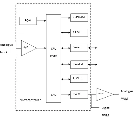
Microcontroller contains a central processing unit (CPU), random access 4
memory (RAM), read-only memory (ROM), electrically erasable programmable 5
read-only memory (EEPROM), input/output (I/O) port, serial and parallel parts, 6
timer, and other built-in peripherals, such as analog-to-digital converter and digital 7
[image:22.595.121.563.311.697.2]to analog converter as shown in Figure 2.0 . 8 9 10 11 12 13 14 15 16 17 18 19 20 21 22
Figure 2.0: Elements in Microcontroller 23 24 Analogue PWM ROM EEPROM Serial RAM TIMER Parallel CPU CORE
CPU PWM
6
1
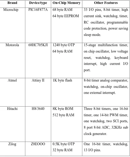
There are many microcontrollers on the market such as Microchip, Motorola, Atmel, 2
Hitachi and Zilog. The features for these microcontrollers are shown in Table 2.0 . 3
[image:23.595.117.548.207.727.2]4
Table 2.0: Various brand of microcontroller 5
Brand Device/type On-Chip Memory Other Features
Microchip PIC16F877A 68 byte RAM 64 byte EEPROM
33 I/O pins, 8-bit timer, high current sink, watchdog, timer, RC oscillator, programmable code protection, power saving sleep mode.
Motorola 68HC705KJI 1240 byte OTP 64 byte RAM
15-stage multifunction timer, on chip oscillator, low voltage reset, watchdog, keyboard interrupt, high current I/O port.
Atmel Attiny II 1K byte flash 8-bit timer analog comparator, watchdog, on-chip oscillator, one external interrupt.
Hitachi H8/3640 8K byte ROM 512 byte RAM
Three 8-bit timers, one 16-bit timer, one 14-bit PWM timer, one watchdog, two SCI ports, 8 port 8-bit ADC, 32KHz sub clock generator.
Zilog Z8EOOO 0.5K byte OTP 32 byte RAM
One 16-bit timer, watchdog, 13 I/O pins.
3
Microchip Technology’s series of microcontroller is called Peripheral 4
Interface Controller (PIC) chips. These RISC-based MCUs are designed for 5
applications requiring high performance and low cost. PIC is generally assumed as 6
programmable interface controller. PIC is the Integrated Circuit (IC) which was 7
developed to control the peripheral device, dispersing the function of the main CPU. 8
9
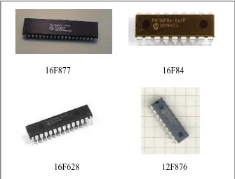
The PIC family includes the 8-pin PIC12Cxxx family, the original 10
PIC16C5x family, the workhorse PIC16Fxxx family, the higher-end PIC 17Fxxx 11
family, and the latest PIC18Fxxx family, which retaining backward compatibility 12
with older members of the PIC line as shown in Figure 2.1. Finally, flash-based PIC 13
is also available. The F in name generally indicates the PIC micro uses flash 14
memory and can be erased electronically. A and C generally means it can only be 15
erased by exposing the die to ultraviolet light. 16
17
18
16F877 16F84 19
20
[image:24.595.169.504.470.726.2]16F628 12F876 21