A Novel Dynamic Overmodulation Strategy
of Direct Torque Control
Auzani Jidin1, Tole Sutikno2, Aiman Zakwan Jidin3, Nik Rumzi Nik Idris4, Abdul Halim Mohd Yatim4
1
Department of Power Electronics and Drives, Universiti Teknikal Malaysia Melaka (UTeM) Hang Tuah Jaya, 76109 Durian Tunggal, Melaka, Malaysia,Ph./Fax: +606-5552345/5552226
2
Department of Electrical Engineering, Universitas Ahmad Dahlan (UAD)
Jln. Prof. Soepomo, Janturan, Yogyakarta 55164, Indonesia, Ph./Fax: +62274-379418/381523 3
Ecole Supérieur d’Ingénieur en Electronique et Electrotechnique (ESIEE Engineering Paris) Cité Descartes - BP 99, 93162 Noisy-le-Grand CEDEX, Ph./Fax: +33145-926500/926699
4
Department of Energy Conversion, Universiti Teknologi Malaysia (UTM)
P07 Building, FKE-UTM, Skudai, 81310 Johor, Malaysia, Ph./Fax: +607-5535356/5566272 e-mail: [email protected], [email protected], [email protected]
Abstrak
Modulasi vektor ruang-kendali torsi langsung (DTC-SVM) telah dikenal baik untuk mendapatkan over modulasi dinamis yang sangat baik. Namun metode ini menggunakan prediksi kendali vektor fluks stator yang rumit dan perhitungan vektor fluks stator yang harus presisi untuk mendefinisikan mode over modulasi. Makalah ini mengusulkan sebuah metode over modulasi mudah dan pengendali frekuensi penyaklaran konstran tanpa modulasi vektor ruang (SVM) untuk mendapatkan tanggapan torsi dinamis yang lebih cepat pada kendali torsi langsung (DTC) untuk motor induksi. Untuk melakukan metode ini, status galat fluks yang dihasilkan dari komparator histeresis fluks selama kondisi dinamis sedikit dimodifikasi sebelum diumpankan ke look-up table. Verifikasi dari dari metode yang diusulkan dilakukan melalui simulasi dengan menggunakan paket MATLAB/Simulink. Efek dari penyaklaran yang berbeda dan kondisi operasi pada kinerja torsi dinamis dianalisis. Hasil simulasi menunjukkan bahwa metode DTC over modulasi dinamis yang diusulkan dapat menghasilkan tanggapan torsi yang lebih cepat. Manfaat utama dari metode yang diusulkan adalah kesederhanaannya, karena hanya sedikit modifikasi dari struktur histeresis DTC dasar.
Kata kunci: DTC, motor induksi, over modulasi, SVM
Abstract
The direct torque control-space vector modulation (DTC-SVM) is well-known for achieving excellent dynamic overmodulation. However, the method uses complicated predictive stator flux vector control and requires high precision stator flux vector to define overmodulation mode. This paper proposes a straightforward dynamic overmodulation method and constant switching frequency controller without SVM to obtain a faster dynamic torque response in DTC for induction machines. To perform this method, the flux error status produced from the flux hysteresis comparator during dynamic condition is modified slightly before being fed to the look-up table. The verification of proposed method was performed using MATLAB/Simulink simulation package. The effects of different switching and operating condition on dynamic torque performance are analyzed. The result shows that a faster torque response is achieved in proposed dynamic overmodulation DTC method. The main benefit of the proposed method is its simplicity since only minor modification is made to the basic DTC hysteresis-based structure.
Keywords: DTC, induction Motor, overmodulation, SVM
1. Introduction
torque control utilizing dynamic overmodulation method. It is a common practice in high performance induction motor drive systems that the overmodulation mode is implemented using space vector modulation (SVM). Dynamic overmodulation operation was specifically discussed for vector control and direct torque control (DTC) drives in several papers [1]-[5].
In the vector control drives utilizing SVM, it is possible to achieve a quick dynamic torque control utilizing inner current loop. Basically, the input modulator of SVM or voltage reference is approximated so that a larger torque producing current component is achieved to produce fast dynamic torque response. In fact, the proper current regulation is extremely important in field oriented control (FOC) system. This becomes problematic (i.e. unstable condition of a high bandwidth of current controller) as the motor currents will have lower order harmonics as it operates in overmodulation region [2]. The problem has been tackled using compensated current with PI current controller as proposed in [3]. In so doing, the scheme eliminates the use of filter which may decrease the bandwidth of current controller and dynamic performance as well.
Alternatively, the DTC-SVM method is much preferred solution since its control structure is simpler than FOC-SVM, due to the absence of the current controller, frame transformer and a position encoder. Habetler et al. proposed dynamic overmodulation utilizing in DTC-SVM to achieve fast dynamic torque response [4], [5]. However, the approximated voltage reference is not capable to exploit the overmodulation region until six-step operation. Hence, this scheme does not give the fastest torque control. Recently, Tripathi et al. proposed dynamic torque control in the overmodulation and field weakening region using DTC-SVM based on stator flux error control [6]. This scheme is able to achieve the fastest torque response in field weakening region with six-step mode. However the structure of the drive system is more complicated than the hysteresis-based structure DTC as proposed by Takahashi.
In DTC-SVM, various methods have been proposed to compute the voltage reference; these include the use of proportional-integral current controller [3], predictive and dead-beat controllers [4][5][6]. For instance, the voltage reference is computed using several complicated equations in real-time [4][5]. Then, the voltage reference (uref) is adjusted (due to physical constraint) to create appropriate voltage reference which is the maximum possible voltage located on the hexagonal boundary. These consequently require major modifications which complicate the basic of DTC structure in [7].
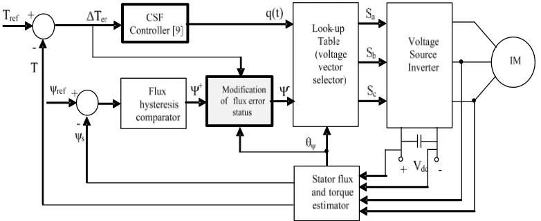
This paper presents a straightforward dynamic overmodulation strategy which can be incorporated in basic of DTC structure (with decoupled of torque and flux control structure) in [7] and [9]. In order to overcome the major problem produced in [7], the method in [9] is proposed to obtain constant switching frequency and torque ripple reduction as well. The operation of the dynamic overmodulation is similar with that proposed in [6] such that in selecting only single voltage vector to produce the largest tangential flux component to obtain the fastest torque response. However, [6] uses DTC-SVM utilizing predictive stator flux vector control which is complicated and moreover the computation to calculate precise stator flux vector used to define overmodulation mode is problematic. In the proposed dynamic overmodulation, the flux error status produced from the flux hysteresis comparator is modified before it is being fed to the look-up table. In such manner, a fast torque response can be achieved with six-step mode under dynamic operating condition. It will be shown that, the proposed dynamic overmodulation is also capable of producing a fast torque response in field weakening region with six-step operation.
2. Proposed Dynamic Overmodulation Method
In the proposed dynamic overmodulation method, the dynamic condition is defined when the torque error exceeds 5% of rated torque. As the dynamic condition is encountered, the original stator flux error status, ψ+ is modified based on information of flux position, θψ to
produce the appropriate flux error status ψ-. In this way, the active voltage vector that produces the largest tangential flux component is switched and held on, to create the largest increase in load angle and hence rapid dynamic torque. The operation of the modification flux error status to perform the proposed dynamic overmodulation can be described as illustrated in flow chart in Figure 2.
Figure 1. Proposed structure for dynamic overmodulation in DTC-CSF based
Figure 2. The operation of the proposed dynamic overmodulation
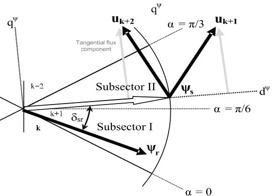
Figure 3 illustrates the two possible selection of voltage vectors (i.e uk+1 and uk+2) during dynamic condition as the stator flux is in sector k+1. The sector is further subdivided into two, namely subsector I and subsector II. The effect of selection of the voltage vectors on the dynamic torque performance will be investigated as the stator flux vector is located within subsector I and subsector II. To study this, the torque equation (1), which expressed torque in terms of stator flux, rotor flux and the angle between the two fluxes, will be used.
sr r s r s
m
e
ψ
ψ
sin
δ
L
σ
L
L
2
3
T
=
(1)Figure 3. Effects of selecting different switching under dynamic condition.
It is obvious from the Figure 3, that the two vectors will give different values of δsr. To obtain the fastest torque response, the vector that gives the largest stator flux tangential component and hence the largest change in δsr should be selected. It can be easily seen from the figure that, selecting uk+1 and uk+2 will ensure the fastest torque response is achieved when the stator flux is located in subsector I and subsector II respectively. The dynamic of the torque will not only depend on these voltage vectors but will also depend on the position of the stator flux at which the instant they are applied, and the speed of the rotor.
3. Research Method
The simulation of the DTC induction motor drive with the proposed overmodulation strategy was performed using MATLAB/Simulink simulation package. The DTC-CSF system and induction machine parameters used in the simulation are given as tabulated in Table 1 and Table 2. The operation of proposed dynamic overmodulation to produce the fastest torque dynamic control in the DTC drive system was verified through MATLAB/Simulink simulations.
Table 1. DTC-CSF system
Parameter value
Proportional gain, Kp 36
Integral gain, Ki 12643
Flux hysteresis band 0.01 Wb
Sampling frequency 40kHz
Switching frequency 4kHz
Table 2. Induction machine parameters
Parameter value
Stator resistance 5.5 Ω
Rotor resistance 4.51 Ω
Stator self inductance 306.5 mH
Rotor self inductance 306.5 mH
Mutual inductance 291.9 mH
Momen of inertia 0.01 kg.m2
Number of poles 4
Rated speed 1410 rpm
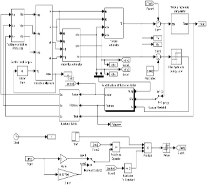
The Simulink blocks of the DTC drive with the modification of flux error status block are shown in Figure 4. The block of the control system can perform into the dual mode of switching operations by toggling the manual switch 1. When the manual switch 1 is switched to the position DTC2, it will pass through the torque error signal ETe to the block of modification of flux error status for detection of torque dynamic condition. When the manual switch 1 selects to the position DTC1, the block of the system will never change the flux error status since the error ETe is assumed always zero, thus, the DTC will operate as usual.
Figure 4. Simulink blocks of the DTC drive with the proposed block of modification of flux error status
Figure 5. Identification of flux sector and determination of the appropriate flux error status in the block of modification of flux error status.
Figure 6. Generation reference torque from 1.5 to 9 Nm at a specific flux positions (i.e. case1 at the middle Sector II or case2 at the boundary Sector I and II).
4. Results and Analysis
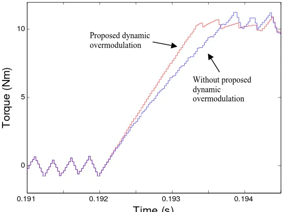
Figure 7 compares the output torque performances during dynamic condition when a step change of speed reference is applied. From the Figure 6, it can be seen that a faster torque response is achieved in the DTC with the proposed dynamic overmodulation than that obtained in the DTC without dynamic overmodulation.
0.191 0.192 0.193 0.194
Figure 7. Output torque transient when a step change of speed reference is applied, for DTC without overmodulation and with the proposed dynamic overmodulation.
The performances of stator flux and d-q current components (correspond to the results obtained in Figure 7) is shown in Figure 8. Apparently, a sharp flux weakening is resulted during the dynamic condition in the proposed method. The sharp flux weakening occurs since the proposed algorithm selects only single active voltage vector during transient condition that produce the largest tangential flux component to achieve the fastest dynamic torque response.
The proposed dynamic overmodulation is capable in achieving fast dynamic torque response for a wide speed operation including the field-weakening region with six-step waveform. It can be shown that, a fast dynamic torque response is achieved since a phase stator voltage is suddenly changed from PWM to six-step operation when the dynamic condition is encountered as depicted in Figure 9.
Without proposed dynamic overmodulation Proposed dynamic
0.1 0.14 0.18 0.22 0.26
Figure 8. Performances of DTC-CSF during dynamic torque condition for (a) without proposed dynamic overmodulation and (b) with proposed dynamic overmodulation.
Figure 9. Proposed dynamic overmodulation in field weakening region with six-step mode.
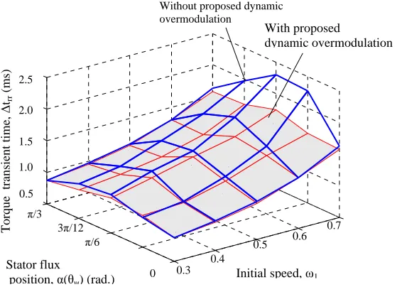
Figure 10 illustrates the effect of stator flux position and rotor speed on the dynamic torque response with and without the proposed technique. In this case the dynamic torque condition is performed as a step change of speed is applied from ω1 (initial speed) to 1.25 times higher than ω1 where the trajectory of stator flux in counter-clockwise rotation reaches at either one, θ =0, π/12, π/6, 3π/12 or π/6 rad. Obviously, a poor dynamic torque performance may result when the dynamic condition occurs at high speed operation and/or the flux position is at around the middle of any flux sector. Through the proposed dynamic overmodulation, a faster dynamic torque response which is lesser rising time, ∆trr can be achieved than that obtained in DTC without dynamic overmodulatrion.
Figure 10. Effects of stator flux location (in a sector) and rotor speed on dynamic torque performance in the proposed DTC scheme.
5. Conclusion
Through the proposed dynamic overmodulation method, a quick dynamic torque control can be achieved by selecting a voltage vector that produces the largest tangential flux component. The proposed method is capable of obtaining the fastest dynamic torque control for any operating conditions including the field weakening region with six-step mode. The proposed dynamic overmodulation resulted in a simple hysteresis-based structure as originally DTC. Only minor modification is needed and no SVM and hence voltage reference are required to be generated. Most of the main components of the basic DTC hysteresis-based structure are retained.
References
[1] Chung DW, Sul SK. A new dynamic overmodulation strategy for high performance torque control of induction motor drives. 14th Applied Power Electronics Conference and Exposition (APEC). Dallas, Texas. 1999; 1: 264-270.
[2] Holtz J, Oikonomou N. Synchronous Optimal Pulsewidth Modulation and Stator Flux Trajectory Control for Medium-Voltage Drives. IEEE Transactions on Industry Applications. 2007; 43(2): 600-608.
[3] Khambadkone K, Holtz J. Compensated synchronous PI current controller in overmodulation range and six-step operation of spacevector-modulation-based vector- controlled drives. IEEE Trans. on Industrial Electronics. 2002; 49(3): 574–580.
[5] Casadei D, Serra G, Tani A, Zarri L, Profumo F. Performance analysis of a speed-sensorless induction motor drive based on a constant-switching-frequency DTC scheme. IEEE Transactions on Industry Applications. 2003; 39(2): 476-484.
[6] Tripathi A. Khambadkone M, Panda SK, Dynamic Control of Torque in Overmodulation and in the Field weakening region. IEEE Transactions on Power Electronics. 2006; 21(4): 1091-1098.
[7] Takahashi I, Naguchi T. A new quick-response and high efficiency control strategy of an induction motor. IEEE Trans. Industry Applications. 1986. IA-22(5): 820–827.
[8] Duran MJ, Barrero F, Prieto J. DC-bus utilization and overmodulation performance of five-phase voltage source inverters using model predictive control. IEEE International Conference on Industrial Technology (ICIT). Viña del Mar, Chile. 2010: 1501-1506.
[9] Idris NRN, Yatim, AHM. Direct torque control of induction machines with constant switching frequency and reduced torque ripple. IEEE Trans. Ind. Electron. 2004; 51(4): 758–767. [10] Idris NRN, Toh CL, Elbuluk ME. A New Torque and Flux Controller for Direct Torque