DOI: 10.12928/TELKOMNIKA.v15i1.3566 4
A Robot Collision Avoidance Method Using Kinect and
Global Vision
Haibin Wu*, Jianfeng Huang, Xiaoning Yang, Jinhua Ye, Sumei He School of Mechanical Engineering and Automation, Fuzhou University, No.2, Xueyuan Road,
Shangjie Town, Fuzhou City, Fujian Prov, 350116, China *Corresponding author, e-mail: [email protected]
Abstract
This paper introduces a robot collision avoidance method using Kinect and global vision to improve the industrial robot’s security. Global vision is installed above the robot, and a combination of the background-difference method and the Otsu algorithm are used. Human skeleton detection is then introduced to detect the location information of the human body. The collided objects are classified into nonhuman and human obstacle which is further categorized into the human head and non-head areas such as the arm. The Kalman filter is used to predict the human gesture. The human joints danger index is used to evaluate the risk level of the human on the basis of human body joints and robot’s motion information. Finally, a motion control strategy is adopted in view of obstacle categories and the human joint danger index. Results show that the proposed method can effectively improve robot’s security in real time. Keywords: robot safety, human body skeleton detection, Kalman filter, global vision, security control
Copyright © 2017 Universitas Ahmad Dahlan. All rights reserved.
1. Introduction
Safety control strategy must be taken to avoid the collision between the moving robot and the operators in the working space [1]. Strategies used in safe human-robot collaboration (HRC) can be broadly divided into two categories: pre-collision strategy [2-4] and post-collision strategy [5]. The former strategy detects the danger before the collision and takes measures to prevent imminent collision. While the latter one requires higher real-time performance during the collision to suppress the impact force, and ensure the security of operators and robots. Therefore, pre-collision methods can normally achieve safer result in implementation of HRC. Researchers have been working on different pre-collision methods and presenting some important findings and solutions. As one of the pre-collision methods, sensors, such as ultrasonic [6] and photoelectric sensors, are installed on the robot to detect the man–machine position. The sensors identify the danger and then the robots will be immediately stopped. Such security strategy is very simple, and greatly reduce the reliability of collision avoidance and the work efficiency of the robot.
The robot should follow the collision avoidance strategy at all run time. A more reliable safety strategy is essential. Sanderud [7] have presented proactive safety strategy based on a quantified measure of risk for human robot collaboration. The risk field is established based on an analysis of the human’s movement and the consequence of a collision with different human limbs, combined with a likelihood analysis. Similarly, a simulation tool using real-world geometrical data was proposed to investigate different algorithms and safety strategies [8]. Kulić [9, 10] suggested a method of robot safe trajectory planning based on the mechanical principle of the minimizing danger index. However, the application of this method is limited by the large number of environmental data required.
and single control strategy. Diffrent actions should be taken for diffrent obstacles in robot work space such as humans, animals and objects. Only depanding robot vision is hard to distingguish all kinds of obstacles, especially for humans and non-humans.
Kinect is an advanced motion tracking sensor, and it can be used for identifying individuals in the robot work space. In [14], an obstacle detection method using Kinect was designed to obtain the obstacle’s information. By designing an artificial parallel system of the manipulator in the obstacle avoidance controller, the proposed control method enables the robot to achieve the ability of moving away from the obstacle. He has also investigated [15] and used Kinect to obtain the obstacle information. This scheme is mainly used for mobile robot to avoid obstacles and is not used in man-machine cooperation environment. Flacco [16] calculated the human–robot distance to determine the danger level and took the safety control measures in the Kinect depth space. This method cannot accurately distinguish human body parts, quantitatively evaluate the movement state, or take effective control measures in time.
This study proposes an improved method to detect and control the robot. Global vision is used to identify the danger of collision. Kinect, combined with the Kalman filter, is used to discriminate the obstacle and detect the human gesture. The specific motion control strategy is adopted depending on different situations.
2. Robot Collision Avoidance System Scheme
As shown in Figure 1, the project consists of a six-degrees-of-freedom (DOF) robot arm, Kinect, an industrial camera, and a personal computer (PC). Kinect and the camera transmit data to the PC by the universal serial bus (USB) port; simultaneously, the PC and the six-DOF robot arm transmit parameters and control movement from each other via the transmission control protocol/internet protocol (TCP/IP). As shown in Figure 1, the industrial camera and Kinect are installed above and in the rear of the six-DOF robot arm, respectively. The detection area can cover the entire working area of the robot arm by adjusting the locations of the industrial camera and Kinect (Figure 2).
Figure 1. System Architecture Model
In this system, the colliding signal of obstacles should be identified first. Hence, global vision and the background-difference method are adopted to detect human and nonhuman obstacles. Upon sensing a potential collision, global vision transmits the danger signal to the robot arm controller for the arm to take safety control measures in time. Kinect then identifies whether or not the obstacle is a part of the human body [17, 18]. If the obstacle is a part of the human body, Kinect combined with the Kalman filter detects and predicts the pose of the human body to calculate the current human joint danger index. This index can be used to classify the danger level compared with the danger index threshold, which transmits different danger signals to make the robot arm take different control strategies.
The Kalman filter can predict the next position and velocity of the object on the basis of the current position of the object [19, 20]. Noise often interferes with the measurement of the position and the velocity of the object; thus, the Kalman filter uses the dynamic information of the object to eliminate the influence of noise and estimate the position of the object accurately.
3. Obstacle Hazard Detection 3.1. Global Vision
3.1.1. Coordinate System Transformation
The Pinhole imaging principle was adopted in this study to understand the transfromation between the image coordinate system and world coordinate system. As shown in
Figure 1, (X , Y Z )c c, c and (X ,Y , Z )w w w are the coordinates of the camera coordinate system and the world coordinate system, respectively. (u, v) is the image pixel as the unit of the image coordinate. Therefore, the expression is [21]
0
w x
ud d
X
. (1)
0
w y
d d
Y
, (2)
where d is the image distance and (0,0) is the center point coordinate of the image plane. The
internal parameters of the camera (
x and
y) must be obtained via camera calibration toconverted the image coordinate system into the world coordinate system. The chessboard method was adopted for calibration. The expression of the relationship between the camera coordinate system and the world coordinate system is:
0 1 0 428 1 0 0 105 0 0 1 1800
1 0 0 0 1 1
c w
c w
c w
X X
Y Y
Z Z
. (3)
Thus, the transformation between the robot arm coordinates system and the image coordinate system can then be realized .
3.1.2. Detect Potential Collision Objects
The entire control system must be in real time. Thus, the image processing data should be minimized and meet the requirements of target detection. Image Pyramid was used to reduce the sampling and the image resolution by Gauss transform.
N y x I y x B
N
i i
1
) , ( ) ,
( . (4)
However, the background-difference method based on the simple background model needs a good threshold; otherwise, achieving the desired detection effect is difficult. Hence, the Otsu algorithm is used to obtain the threshold value that improves the detection effect of obstacles. Using the Otsu algorithm, the calculation of each frame requires approximately 300 ms in the experiment, and it cannot meet the real-time requirements of the system. Therefore, the method cannot be directly applied to the operating process of the system. The working environment of the system is human-controlled, and environmental brightness is the main influencing factor. Therefore, different brightness levels were used in this study by changing the number of lights in the working environment, and the threshold segmentation algorithm was used to calculate the current best threshold for each brightness level. The separate targets that were adopted to calculate the separation threshold include the head, the arm, and some nonhuman obstacles. Thus, the background-difference method based on the simple background model can not only meet real-time requirements but also detect obstacles accurately.
Table 1. OTSU Algorithm to Find the Brightness Threshold Light number 2 3 4
Threshold 90 86 78
Finally, the image was corrupted and expanded by senior morphology transformation. All of the contours in the binarization image were detected and the information of the most outside rectangle boundary was calculated, including the center point coordinates, and the rectangle’s length (L) and width (W). Image interference can be partially eliminated by discriminating each contour.
3.2. Human Body Posture Recognition and Detection
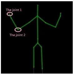
Kinect was used to detect human skeleton information and combined with the Kalman filter to predict human posture. Taking the first left arm joint in Figure 3 as an example, we discuss the realization of the Kalman filter in the X axis below and show that it is similar to the Kalman filter in the Y axis.
Figure 3. Human Body Joints in Kinect
3.2.1. Establishment of the Kalman State Equation The motion equation of joint 1 is:
t
k k
k
x
v
x
1
(5)t
kx kx
kx v a
where
x
k,v
kx, and kxa
are the coordinates, velocity, and acceleration of joint 1 in the X axis in K time, respectively, and t is the time interval between the two frame images.a
kxt
can be used as white noise in the practical calculation.The position and velocity of the joint point can be expressed by the state equation of the joint point, velocity information also contains motion direction information. Therefore, the state equation can be established by the motion equation of the joint 1. The system state equation is computed as t t kx kx k kx k a v x v x 0 1 0 1 1 1 . (7)
3.2.2. Establishment of the Kalman System Observation Equation [22]
The Kalman system observation vector not only corrects the prediction data of the last round of Kalman iterative algorithm, but also prepares for the next round of iterative algorithm. Because the observed joint position is the actual position of the joint pointion in the Kinect coordinate system, the joint position is calculated as:
kx k kx k v x v x 0 1 1 1 , (8)and the observation coefficient matrix is:
1 0 0 1 ) (k F . (9)
3.2.3. Initialization Filter
First round iteration of Kalman filter needs to intitialize various vectors. When the human body first appeared, according to the observational position of human joints, the filter state is initialized to:
T x,0 0 0 0 S
. (10)
The system initial state vector covariance matrix could obtain a large value from the diagonal of the matrix. The values are obtained according to the actual measurement situation and are not influenced after filtering for some time. For the first time, the value is:
22 22 2
/ 10 / 10 / 10 10 ) 0 0 ( t t t P
. (11)
The system dynamic noise covariance matrix is:
10 0 0 10 0 Q . (12)
3.2.4. Kalman Filtering Algorithm Iterative Process
On the basis of the state vector prediction equation, the state of joint 1 in frame k+1 of image is predicted to be:
) ( ) ( ) 1
(k k k kk
H S
S . (13)
The prediction equation of the state vector covariance matrix is:
) ( ) ( ) ( ) ( ) 1
(k k k kk T k k
Q H P H
The Kalman weighting matrix is computed as: ) ) 1 ( ) 1 ( ) 1 ( ) 1 ( )( 1 ( ) 1 ( ) 1
(k k k T k k k k T k βk 1
F P F F P
K . (15)
The state vector update equation is computed as:
)) 1 ( ) 1 ( ) 1 ( )( 1 ( ) 1 ( ) 1 1
(k k k k k k k k k
S F X K S
S . (16)
The state vector covariance update equation is computed as:
) , 1 ( )) 1 ( ) 1 ( ( ) 1 1
(k k IKk Fk Pk k
P . (17)
The states of joints 1 and 2 in the next frame can be predicted. Furthermore, state prediction was combined with the precise joint data provided by Kinect. After a short iterative process, constantly updating the state vector and its covariance matrix using Equation (14) to (17) increases the accuracy of the prediction position. Thus, the velocity vector of the joint motion can be calculated.
3.3. Danger Index
When robot arm moves, the state of human body’s movement plays an impotant role in affecting collision risk leve. Different parts of the human body can bear different degree of impact force. Therefore, distinguishing the different parts of the human body in detecting collision danger and quantifying the level of danger in each body part are crucial. Take the human head and arm as examples, the experimental results show that the motion control strategy is effective in calculating, illustrating, and setting the specific motion control strategy.
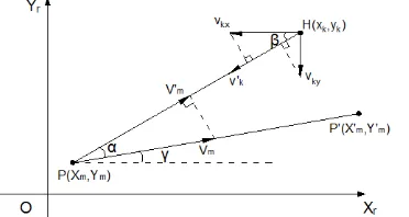
As shown in Figure 4, the start and end points of the robot arm movement are P X Y( m, m) and P X'( ' , ' )mYm , respectively.
Figure 4. Relative Motion between Human and Robot
Suppose the human’s left arm to be a potential collision site, joint 1 will be considered to be the reference point if it is closer to the robot arm comparing to the others. As shown in Figure 4, the instant velocities of joint 1 in the Xr and Yr axes of the robot arm coordinate system are vkx and vky, respectively. The velocity component of joint 1 in the line between the center
point and the robot arm is vk, and it is the sum of vkx and vky in this line. vm is the velocity vector of the robot arm joint movement, vm is the velocity component of the robot in this line, and Xm and Ym are the coordinates of the robot arm joint in the Xr and Yr axes, respectively. As a quantitative analysis parameter of collision, the danger index is calculated only when the danger signal is detected. Therefore, the danger index is 0 in the safe state. The human joint danger index is computed as:
tan k m
k m
y Y x X
' tan
'
m m
m m
Y Y X X
(19)
(20)
cos
mv
mv
(21)
sin
cos
kv
kxv
kyv
(22)
safety y
x condition
danger y
x condition X
x X x
DI k m
m k
m k
) , ( 0
) , ( ( ' ')
v v
, (23)
where vk and vm are the velocity vectors, which include the moving direction information of the
industrial robot and the human body joint. Therefore, the danger index also contains the direction information of the relative movement of the robot arm and joint 1, and the danger index plays a vital role in detecting the danger signal.
If joint 2 is closer to the robot arm than other parts, then it is used as a reference point. When the obstacle is a human head, the calculation is the same as above. The method is based on the danger index and combined with global vision’s obstacle information detection to sense the collision danger in real time.
4. Specific Motion Control Strategy
When detecting the collision danger, control measures must be taken effectively to ensure safety. In this study, the situation where the obstacle is a human body or a different part of a human body determines which effective control strategy should be taken, as well as which strategy can make the system successfully protect the robot arm and the people [23].
The collision danger signal is composed of the signals provided by Kinect and global vision, which determine the type of obstacle and the danger degree of collision. Therefore, the selection of the control strategy is mainly based on the following three aspects:
(1) The control strategy can protect the robot as much as possible, so that the robot will deal with an impending dangerous situation better.
(2) When the obstacle is a part of the human body, the control strategy should give the human body the priority protection.
(3) The control strategy, in the role of protection, should not affect the efficiency of the robot after the danger signal released.
4.1. If the Obstacle is not human
The robot arm was controlled to move vertically along the direction of the end-effector and the obstacle center. While image processing, the center point coordinates of the obstacle
detection is A(x, y), the end-effector coordinates of the robot arm is B(x , y )1 1 , the end-effector
velocity of the robot arm is Vr(P), and the motion velocity of the robot arm after control
measures is Vpivot(P). The robot arm collision avoidance trajectory was calculated by the
following algorithm.
When the danger signal is detected, the vector
a
between the end-effector of the robot arm and the obstacle center is:BA BA
a . (24)
) ( ) ( P P r r V V
r . (25)
If ,
)
arccos(
a
Tr
(26)
2 (27)
)
cos(
)
(
)
(
P
rP
pivot
V
V
, (28)where
is the angle between the velocity vector of the end-effector and the direction vector ofthe obstacle. If 2
, then the robot arm and obstacles are far from each other, and taking control measures is not necessary.
4.2. If the Obstacle is a Human Head
When the danger index DI>F (where F is a pre-set head danger index threshold), the robot arm has a repulsion action to the head, and the direction of the robot arm is far from the head. ) ( ) ( P P r r V V
r (29)
When the danger signal was detected by global vision, the robot arm was controlled in the reverse direction in accordance with the following equation:
)1) / 2 )( / 1 (( 1 ) ( ) ( ) ( kx e P P r pivot v V r V
, (30)
where
is the safe detection distance of robot andv
kx is the motion velocity of obstacle. Theshape factor
was taken as 6 in the experiment. When the danger signal was released, the human head is still in the area of robot movement.0 ) (P
pivot
V . (31)
The robot movement would be recovered after the human head left the area.
4.3. If the Obstacle is the Arm
When the danger index DI>Fh (where Fh is a pre-set head danger index threshold), the robot arm was controlled to move along the direction of the end-effector and the center of the arm, and a new path to the target point was planned.
The acceleration of the robot’s end-effector is computed as:
dt P d dt P d r r )) ( ( )) ( ( V V a
. (32)
The moving direction vector of end-effector is computed as:
) ( ) ( P P r r V V r
. (33)
2
The angle between the velocity vector of the end-effector and the acceleration vector of the end-effector is
.)
arccos(
a
Tr
(34)If ,
r
a
n
(35)a n
a n v
(36)
c dt
P d dt
P
d r r
e ) 1)
)) ( ( / 2 ( )) ( ( (
1
2
V V
(37)
)
sin
(cos
)
(
)
(
V
a
v
V
pivotP
rP
, (38)
where c is the proportional constant and was taken as 5 in the experiment. The arm center
coordinates is A(x, y), and the length and width of the arm’s outer contour are L and W, respectively, by global vision. When the position coordinate of the robot is xxL/2, the robot moved to a safe position. Then, the robot was controlled to move along a new path to the target point.
5. Experimental Results and Analysis
The experimental platform is the six-DOF ABB robot arm that communicates with a PC having CPU(Intel Core i3-4130 3.4GHz)and 4GB RAM through the PC interface. First-generation Kinect sensors and a 1 200 000 pixel industrial camera were used to get the detecting data. The system was implemented in VS2010 to process images and analyze data.
5.1. Human Gesture Prediction Experiment
In order to verify the reliability of this study for human gesture prediction, the error of Kinect detection and Kalman filter detection must be tested and verified. In the experiment, using Kinect to track the motion of the hand and the head in the Xr axis of the robot coordinate system and then combined with the Kalman filter to predict the moving gesture of the human’s hand and head. As shown in Figure 5 and Figure 6, the white rectangle was the changeable position of the hand and the head, the white line was the path of the palm and the head. In order to contrast the actual values of the hand and head with Kinect detection value and Kalman filter values, the tape was set up in the experiment, and the hand and the head moved along the direction of tape. The actual value, Kinect detection value and Kalman filter values of the hand and head are shown in Figure 7, respectively. The error between the actual value and the Kinect detection value, as well as the error between the actual value and the Kalman filter values are shown in Figure 8, respectively.
A typical experiment result is presented in Figure 7. Both the Kinect detection value and the Kalman filter value are almost the same as the actual value as shown in Figure 7. The error of the Kinect detection value and the error of the Kalman filter value are summarized in Figure 8, respectively. Both the absolute error of the Kinect detection value and the Kalman filter value are below 50mm. Therefore, the detection error is negligible, and will not affect the outcome of human gesture prediction. In summary, using Kinect combined with the Kalman filter to predict the human gesture is reliable and practicable.
2
(a) 120th Frame Image (b) 180th Frame Image
Figure 5. Hand Tracking
(a) 120th Frame Image (b) 180th Frame Image
Figure 6. Head tracking
(a) Hand Tracking Filter Results (b) Head Tracking Filter Results
Figure 7. Hand and Head Tracking Filter Results
(a) Head Detection Error (b) Head Detection Error
5.2. The Robot Collision Avoidance Experiment
To verify the real-time and effectiveness of the system, a series of experiments was carried out in terms of the following situations.
5.2.1. The ObstacleiIs Not Human
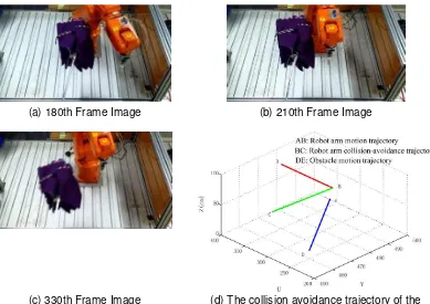
An umbrella was placed in the robot’s working space, and the robot’s moving trajectory passed the position of the umbrella. When the umbrella is detected as an obstacle by the system, the system would control the robot arm to stop the movement and escape in the reverse direction (Figure 9). For instance, when the robot arm is moving close to the umbrella (Figure 9a), the system detects that the robot arm is too close to the umbrella, and the robot arm would stop (Figure 9b). The system would further avoid collision by taking other measures (Figure 9c). The collision avoidance trajectory of the end-effector in its working space is shown in Figure 9d. When the obstacle reach the dangerous point, the robot arm moves to the safe direction according to the collision avoidance trajectory, thus it will avoid the collision in time (Figure 9).
(a) 180th Frame Image (b) 210th Frame Image
(c) 330th Frame Image (d) The collision avoidance trajectory of the end-effector
Figure 9. Safety control process of a non-human obstacle
5.2.2. The Obstacle is the Head and the Danger Index f>F
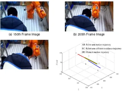
When a head is detected as an obstacle by the system and judged at risk, the system will control the robot arm to move along the reverse direction of the head’s movement (Figure 10). For instance, when a head appears in the moving space of the robot arm and both are approaching each other (Figure 10a), the system will detect the collision danger between the head and the robot arm (Figure 10b). The robot arm then retreats in the reverse direction, and the head continues to move at the same time (Figure 10c). The collision avoidance trajectory of the end-effector in its working space is shown in Figure 10d.
(a) 150th Frame Image (b) 205th Frame Image
(c) 250th Frame Image (d) The collision avoidance trajectory of the end-effector
Figure 10. Safety Control of the Head in a Dangerous Situation
5.2.3. The obstacle is the arm and the danger index f>Fh
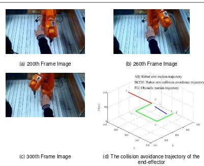
When the palm is detected as an obstacle by the system and judged at risk, the system would control the robot arm to retreat vertically along the vector direction of the palm (Figure 11). When the palm appears in the moving space of the robot arm, the system detects the collision danger (Figure 11a). The robot arm retreats vertically along the vector direction of the palm (Figure 11b) and then moves along a new trajectory to the original target (Figure 11c). The collision avoidance trajectory of the end-effector in its working space is shown in Figure 11d.
When the palm reaches the dangerous point, the robot arm timely moves to the safe direction according to the collision avoidance trajectory. When the robot reaches the safety position, the system re-planning of the trajectory so that the robot reaches the original target ‘s position (Figure 11).
(a) 200th Frame Image (b) 260th Frame Image
(c) 300th Frame Image (d) The collision avoidance trajectory of the end-effector
Figure 11. Palm’s Safety Control in a Dangerous Situation
6. Conclusion
This paper presents a pre-collision method based on global vision and Kinect for robot movement’s security. The system is simple in structure because it can recognize the human body and nonhuman obstacles accurately and calculate the danger index by using the Kinect and Kalman filter algorithm when the obstacle is a human body. Moreover, the danger index is used as a basis by the system when assuming a different security control strategy, thereby ensuring the safety of the human body and the robot arm.
This pre-collision method can be applied to man-machine cooperation of industrial robots. A series of experiments on the six-DOF ABB robot arm using this system confirmed the real-time effectiveness and satisfactory performance of the method. Thus, the method can improve the safety of the robot’s movement effectively when the effect on the working efficiency of the robot is minimal.
Acknowledgements
This study is supported by the National Natural Science Foundation of China (No. 5117 5084 and 51575111), and University-Enterprise Cooperation Project (2015H6012).
References
[1] Haibin Wu, Jianming Yang. Progress in robot safety research during human-robot interaction. China Safety Science Journal. 2011; 21(11): 79-86. (Chinese)
[2] Flacco F, De Luca A. Multiple Depth/Presence Sensors: Integration and Optimal Placement for Human/Robot Coexistence. Robotics and Automation (ICRA), 2010 IEEE International Conference on. 2010; 3916–3923.
[4] Carlos Morato, Krishnanand N Kaipa, Boxuan Zhao et al. Toward Safe Human Robot Collaboration by Using Multiple Kinects Based Real-time Human Tracking. Journal of Computing and Information Science in Engineering. 2014; 14(1): 011006.
[5] Dongjun Shin, Irene Sardellitti, Yong-Lae Park et al. Design and Control of a Bio-Inspired Human-Friendly Robot. The International Journal of Robotics Research. 2010; 29(5): 571-584.
[6] Donghe Yang, Xiang Liu. Research of intelligent mobile robot’s obstacle avoidance based on
ultrasonic sensor. Computer Engineering and Design. 2007; 28(15): 3659-3660. (Chinese)
[7] Audun sanderud, Trygve Thomessen, Hisashi Osumi et al. A Proactive Strategy for Safe Human-Robot Collaboration based on a Simplified Risk Analysis. Modeling, Identification and Control. 2015; 36(1): 11-21.
[8] Paul Bobka, Tomas Germann, Jakob K.Heyn et al. Simulation Platform to Investigate Safe Operation of Human-Robot Collaboration Systems. Procedia CIRP. 2016; 44: 187-192.
[9] D. Kulić, E. Croft. Real-time safety for human-robot interaction. Robotics and Autonomous Systems.
2006; 54 (1): 1-12.
[10] D. Kulić, E. Croft. Pre-collision safety strategies for human-robot interaction. Autonomous Robots. 2007; 22(2): 149-164.
[11] Rafiq Ahmad, Peter Plappera. Safe and Automated Assembly process using Vision assisted Robot Manipulator. Procedia CIRP. 2016; 41: 771-776.
[12] Rafiq Ahmad, Peter Plappera. Human-Robot Collaboration: Twofold Strategy Algorithm to Avoid collisions Using TOF Sensor. International Journal of Materials, Mechanics and Manufacturing. 2016; 4(2): 144-147.
[13] S. Kuhn, D. Henrich. Fast vision-based minimum distance determination between known and unkown objects. Proceedings of the 2007 IEEE/RSJ International Conference on Intelligent Robots and Systems. San Diego, CA, USA. 2007; 2186-2191.
[14] Xinyu Wang, Chenguang Yang, Junshen Chen, Hongbin Ma, Feng Liu. Obstacle Avoidance for Kinematically Redundant Robot. IFAC-PapersOnLine. 2015; 48(28): 490-495.
[15] Chao He, Huaping Liu, Fuchun Sun et al. Target tracking and obstacle avoidance of mobile robot using Kinect. CACI Transactions on Intelligent Systems. 2013; 8(5): 426-432. (Chinese)
[16] F. Flacco, T. Kröger, A. D. Luca, and O. Khatib. A depth space approach to human-robot collision avoidance. 2012 IEEE International Conference on Robotics and Automation. RiverCentre, Saint Paul, Minnesota, USA. 2012; 338-345.
[17] Cheng Huang, Huaping Liu, Xiaowu Zuo et al. Human-robot cooperation using Kinect. Journal of Central South University (Science and Technology). 2013; 44(1): 386-393. (Chinese)
[18] Abdul Muis, Wisnu Indrajit. Realistic Human Motion Preservation-Imitation Development on Robot with Kinect. TELKOMNIKA. 2012; 10(4): 599-608.
[19] Liangsong Huang, Xiaoli Guo, Yuxia Li. Application of Kalman filter on mobile robot self-localization. Journal of Measurement Science and Instrumentation. 2014; 5(2): 52-54.
[20] Performance Evaluation of MMA7260QT and ADXL345 on Self Balancing Robot. TELKOMNIKA. 2013; 11(1): 1-10.
[21] Yanxiang Han, Zhisheng Zhang, Min Dai. Monocular vision system for distance measurement based on feature points. Optics and Precision Engineering. 2011; 19(5): 1110-1117. (Chinese)
[22] Qingying Li, Jinkui Chu, Ronghua Li, Hongqing Wang. Moving object tracking algorithm for mobile robot based on Kalman filter. Transducer and Microsystem Technologies. 2008; 27(11): 66-71. [23] Xuesong Yan, Qinghua Wu, Hammin Liu. An Improved Robot Path Planning Algorithm.