Open Geospatial Consortium
Approval Date: 2011-12-09 Publication Date: 2012-05-15
External identifier of this OGC® document: http://www.opengis.net/doc/ER/ows8-tracking-vmti
Reference number of this document: OGC 11-134 Category: Public Engineering Report
Editor(s):Rob Cass, Mark Simms
OGC
®OWS-8 Tracking: Moving Target Indicator Process,
Workflows and Implementation Results ER
Copyright © 2012 Open Geospatial Consortium.
To obtain additional rights of use, visit http://www.opengeospatial.org/legal/.
Warning
This document is not an OGC Standard. This document is an OGC Public
Engineering Report created as a deliverable in an OGC Interoperability Initiative and is not an official position of the OGC membership. It is distributed for review and comment. It is subject to change without notice and may not be referred to as an OGC Standard. Further, any OGC Engineering Report should not be referenced as required or mandatory technology in procurements.
Document type: OpenGIS® Engineering Report Document subtype: NA
Preface
The scope of this report is to provide a description of services, data storage and data movement within the OWS-8 Tracking sub-thread. The paper outlines the development of Sensor Observation Services (SOS), a Web Feature Service(WFS), a Notification Service and a Web Processing Service (WPS) for generating track features. Additionally, implemented encodings will be discussed as examples and in comparison to the
encodings detailed in (Simonis, 2011).
This document is a deliverable for the OGC Web Services 8 (OWS-8) testbed activity. OWS testbeds are part of OGC's Interoperability Program, a global, hands-on and collaborative prototyping program designed to rapidly develop, test and deliver proven candidate standards or revisions to existing standards into OGC's Standards Program, where they are formalized for public release. In OGC's Interoperability Initiatives,
international teams of technology providers work together to solve specific geoprocessing interoperability problems posed by the Initiative's sponsoring organizations. OGC
Interoperability Initiatives include test beds, pilot projects, interoperability experiments and interoperability support services - all designed to encourage rapid development, testing, validation and adoption of OGC standards.
The OWS-8 sponsors are organizations seeking open standards for their interoperability requirements. After analyzing their requirements, the OGC Interoperability Team
recommend to the sponsors that the content of the OWS-8 initiative be organized around the following threads:
* Observation Fusion
* Geosynchronization (Gsync)
* Cross-Community Interoperability (CCI) * Aviation
More information about the OWS-8 testbed can be found at:
http://www.opengeospatial.org/standards/requests/74
OGC Document [11-139] “OWS-8 Summary Report” provides a summary of the OWS-8 testbed and is available for download:
License Agreement
Permission is hereby granted by the Open Geospatial Consortium, Inc. ("Licensor"), free of charge and subject to the terms set forth below, to any person obtaining a copy of this Intellectual Property and any associated documentation, to deal in the Intellectual Property without restriction (except as set forth below), including without limitation the rights to implement, use, copy, modify, merge, publish, distribute, and/or sublicense copies of the Intellectual Property, and to permit persons to whom the Intellectual Property is furnished to do so, provided that all copyright notices on the intellectual property are retained intact and that each person to whom the Intellectual Property is furnished agrees to the terms of this Agreement.
If you modify the Intellectual Property, all copies of the modified Intellectual Property must include, in addition to the above copyright notice, a notice that the Intellectual Property includes modifications that have not been approved or adopted by LICENSOR.
THIS LICENSE IS A COPYRIGHT LICENSE ONLY, AND DOES NOT CONVEY ANY RIGHTS UNDER ANY PATENTS THAT MAY BE IN FORCE ANYWHERE IN THE WORLD.
THE INTELLECTUAL PROPERTY IS PROVIDED "AS IS", WITHOUT WARRANTY OF ANY KIND, EXPRESS OR IMPLIED, INCLUDING BUT NOT LIMITED TO THE WARRANTIES OF MERCHANTABILITY, FITNESS FOR A PARTICULAR PURPOSE, AND NONINFRINGEMENT OF THIRD PARTY RIGHTS. THE COPYRIGHT HOLDER OR HOLDERS INCLUDED IN THIS NOTICE DO NOT WARRANT THAT THE FUNCTIONS CONTAINED IN THE INTELLECTUAL PROPERTY WILL MEET YOUR REQUIREMENTS OR THAT THE OPERATION OF THE INTELLECTUAL PROPERTY WILL BE
UNINTERRUPTED OR ERROR FREE. ANY USE OF THE INTELLECTUAL PROPERTY SHALL BE MADE ENTIRELY AT THE USER’S OWN RISK. IN NO EVENT SHALL THE COPYRIGHT HOLDER OR ANY CONTRIBUTOR OF
INTELLECTUAL PROPERTY RIGHTS TO THE INTELLECTUAL PROPERTY BE LIABLE FOR ANY CLAIM, OR ANY DIRECT, SPECIAL, INDIRECT OR CONSEQUENTIAL DAMAGES, OR ANY DAMAGES WHATSOEVER RESULTING FROM ANY ALLEGED INFRINGEMENT OR ANY LOSS OF USE, DATA OR PROFITS, WHETHER IN AN ACTION OF CONTRACT, NEGLIGENCE OR UNDER ANY OTHER LEGAL THEORY, ARISING OUT OF OR IN CONNECTION WITH THE IMPLEMENTATION, USE, COMMERCIALIZATION OR PERFORMANCE OF THIS INTELLECTUAL PROPERTY.
This license is effective until terminated. You may terminate it at any time by destroying the Intellectual Property together with all copies in any form. The license will also terminate if you fail to comply with any term or condition of this Agreement. Except as provided in the following sentence, no such termination of this license shall require the termination of any third party end-user sublicense to the Intellectual Property which is in force as of the date of notice of such termination. In addition, should the Intellectual Property, or the operation of the Intellectual Property, infringe, or in LICENSOR’s sole opinion be likely to infringe, any patent, copyright, trademark or other right of a third party, you agree that LICENSOR, in its sole discretion, may terminate this license without any compensation or liability to you, your licensees or any other party. You agree upon termination of any kind to destroy or cause to be destroyed the Intellectual Property together with all copies in any form, whether held by you or by any third party.
Except as contained in this notice, the name of LICENSOR or of any other holder of a copyright in all or part of the Intellectual Property shall not be used in advertising or otherwise to promote the sale, use or other dealings in this Intellectual Property without prior written authorization of LICENSOR or such copyright holder. LICENSOR is and shall at all times be the sole entity that may authorize you or any third party to use certification marks, trademarks or other special designations to indicate compliance with any LICENSOR standards or specifications.
This Agreement is governed by the laws of the Commonwealth of Massachusetts. The application to this Agreement of the United Nations Convention on Contracts for the International Sale of Goods is hereby expressly excluded. In the event any provision of this Agreement shall be deemed unenforceable, void or invalid, such provision shall be modified so as to make it valid and enforceable, and as so modified the entire Agreement shall remain in full force and effect. No decision, action or inaction by LICENSOR shall be construed to be a waiver of any rights or remedies available to it.
Contents
Page1 Introduction ... 1
1.1 Scope ... 1
1.2 Document contributor contact points ... 1
1.3 Revision history ... 1
5 Implementation resultsoverview ... 5
6 SOS implementation ... 8
6.1 Available data sets ... 9
6.2 The Frame offering ... 9
6.3 The TargetResult Offering ... 11
6.4 The Video Offering ... 13
6.5 The Frame Image Offering ... 14
7 WPS Tracker implementation ... 14
7.1 Tracker Algorithm ... 14
7.2 Tracker Inputs and Execution Sequence ... 15
7.3 Lessons learned and discussions ... 16
7.3.1 Target Characteristics and Algorithm Traceability ... 16
Problems: ... 16
7.3.2 Target Motion Metrics for Detections ... 19
7.3.3 Sensor Metadata for Frame Co-Registration ... 20
7.3.4 Cross-referencing for Performance – Incremental Processing ... 22
7.3.5 Accurate Target Detection for Performance – One Target One Detection ... 24
7.3.6 Multiple Target Detections for Performance – Moving Targets in Different Directions ... 26
8 Web Feature Service implementation ... 28
8.1 Feature Type Implementations in the WFS ... 29
8.1.2 Updating Track Data ... 35
9 Notification Service implementation ... 35
9.1 OASIS Web Services Notification (WSN) ... 35
9.2 SubscriptionManager ... 35
9.2.1 Subscribe ... 36
9.2.2 Renew ... 37
9.2.3 Topics ... 38
9.3 Notifications ... 38
9.3.1 Match ... 39
9.3.2 Transaction ... 40
10 Client Implementation ... 41
10.1 Client Data Flows ... 41
10.2 GeoSMS notification ... 46
10.3 Mobile Client Implementation ... 49
Annex A Example Requests and Responses ... 51
Annex B XML Schema Documents ... 61
Bibliography ... 68
Figures
Page Figure 1 – Proposed Architecture (Simonis 2011) ... 6Figure 2 – Implemented Architecture ... 7
Figure 3 – Storage of Video Frame and Detection Information in SOS ... 9
Figure 4 – Example of Frame Polygon Sampling Feature ... 10
Figure 5 -- Tracker Inputs ... 15
Figure 6 -- WPS Sequence Diagram ... 16
Figure 7. Target width in MISB 0601 ... 17
Figure 8. Target Track Gate width and height in MISB 0601 ... 17
Figure 9. Target size information in one detection example ... 18
Figure 10. Speed and acceleration tag in MISB 0903 ... 20
Figure 11. Camera metadata of MISB 0601 in the example dataset ... 21
Figure 12. Frame 2012 retrieved from the SOS ... 23
Figure 13. Frame 2007 retrieved from the SOS ... 24
Figure 14. Multiple detections for single target in one frame ... 25
Figure 17. Another vehicle is detected and tagged in another adjacent frame although both
vehicles present ... 28
Figure 18 -- STANAG 4676 Data Model ... 30
Figure 19 -- STANAG Data Model Cont. ... 31
Figure 20 -- Client use of services ... 43
Figure 21 -- Track Display Using a WMS ... 44
Figure 22 -- Track Point Interface ... 45
Figure 23 -- Frame Image with highlighted Detection ... 45
Figure 24 - Subscribing to a Broker ... 47
Figure 25 - Subscription from Broker to Subscription Manager ... 48
Figure 26 -- Notification Process ... 49
Tables
Page Table 1 – Frame Offering ... 10Table 2 – Target Result Offering ... 12
Table 3 -- STANAG 4676 Fields ... 34
OGC
®OWS-8 Tracking: Moving Target Indicator Process,
Workflows and Implementation Results ER
1 Introduction
1.1 Scope
The scope of this report is to provide a description of services, data storage and data movement within the OWS-8 Tracking sub-thread. The paper outlines the development of Sensor Observation Services (SOS), a Web Feature Service(WFS), a Notification Service and a Web Processing Service (WPS) for generating track features. Additionally, implemented encodings will be discussed as examples and in comparison to the
encodings detailed in (Simonis, 2011). 1.2 Document contributor contact points
All questions regarding this document should be directed to the editor or the contributors:
Name Organization
Rob Cass Compusult Ltd.
Mark Simms Compusult Ltd.
Genong Yu George Mason University
Hsiu-Yi Ko GIS.FCU
1.3 Revision history
Date Release Editor Primary clauses
modified
Description
2011-09-26 Draft Rob Cass All Initial Draft
1.4 Future work
(WPS) designed to use the SOS to generate track data and insert that data into a WFS. A number of future work items can be derived from this implementation.
SWE Observation representations of VMTI detection metadata: For OWS-8,
VMTI data was obtained from 2 video files provided by the Australian DSTO. The target detection information available within these files fit the EG0903.0 Local Data Set model. As the EG0903 set of standards moves forward (EG0903.2 is now a recommended practice), the level of sophistication for the observation information stored in the SOS must consequently increase. While a
straightforward “flat” approach to encoding properties of a Local Data Set could suffice for EG0903.0, developments within the EG0903.2 standard e.g. chip run-length encodings require a hierarchical structure for detections, frame information etc. This hierarchical structure is detailed in (Simonis, 2011).
Complete representation of STANAG 4676 concepts as GML: For OWS-8,
derived track information was stored in a WFS. This information was encoded in a GML representation which was based on, but did not fully implement all the concepts developed in the STANAG 4676 standard. The goal for the test bed was to have a geo-referenced model of the essential track information for querying and display purposes. In order to develop a complete and useful representation of the track data emitted from any tracker, there must be support for topological
dependencies between the identified feature types such as track points, segments and tracks themselves.
Accumulation and storage of evidence: For the track point information
developed by the WPS in OWS-8, the individual frame from which a track point was derived was identified in the TrackItem feature. This was a URL to a frame item in the SOS. Further work needs to be done to identify a shared encoding model for any evidence used by the Tracking software. This would be a document or feature with appropriate evidence links maintained by the tracker as it does its analysis of the raw data. This evidence could be associated with a complete Track or its components. What is a useful degree of detail, and what the evidence encoding should be need to be developed in cooperation with domain experts.
Development of Standardized Property Definitions: As a means for clearly
defining each observed property derived from the raw observation data and providing a link between OGC encodings and published standards from MISB and other standards bodies, it may be necessary to develop a set of mappings between MISB and STANAG observables and OGC encoded observables. At the very least, URIs should be identified and agreed upon for observable properties. This was done in a basic way for the test bed, but would need to be developed in further work.
Enablement approach is to embed a URL to the imagery in an Observations and Measurement response and then use this URL to retrieve this data OR to embed a base64 encoded version of the stream in the Observations and Measurements XML. While the former approach is reasonable and was implemented in OWS-8, it is not a way to directly deliver the imagery and the latter approach has scaling issues when embedding FMV in XML. A related implication is that the
architecture could move to a transactional scenario where the video data is transacted to an SOS as an observation. A clear way to fit such a transaction into the SWE framework might also need to be developed. While traditionally, Motion Imagery has had no rigorous geospatial reference, and would thus fall out of the scope of the OGC, recent developments point to a need to define how to deliver FMV directly as an extension to some existing OGC service or as a new service definition.
GMTI Observation Fusion: While not available within the testbed, there is an expressed need for working with Ground Motion Target Indicators provided from Radar detections. GMTI encodings for SWE have been developed in (Simonis, 2011) and could be implemented provided that test beds have access to GMTI data and decoders. GMTI presents another set of challenges for developing track data and evidence retrieval.
Integration with available 4676 data: Further work in implementing tracking architectures would benefit from exposure to simulated to track data as it evolved from points, segments etc. into track features. References have been made to the track life cycle and reference data would be beneficial for analysis and
implementation guidance.
1.5 Forward
Attention is drawn to the possibility that some of the elements of this document may be the subject of patent rights. The Open Geospatial Consortium Inc. shall not be held responsible for identifying any or all such patent rights.
Recipients of this document are requested to submit, with their comments, notification of any relevant patent claims or other intellectual property rights of which they may be aware that might be infringed by any implementation of the standard set forth in this document, and to provide supporting documentation.
2 References
In addition to this document, this report includes an XML Schema Document file as specified in Annex B.
3 Terms and definitions
3.1 track
Definition from (NATO Standardization Agency, 2011),a set of associated state vector estimates describing the time-referenced, kinematic behavior, and other relevant
characteristics of an object or group of objects.
3.2 target
an encoded moving object detection embedded within a VMTI or GMTI data stream NOTE For the purposes of this report, a VMTI data stream. Targets are encoded as VTargets within a VTargetSeries provided in a Local Data Set packet according to (Motion Imagery Standards Board, 2009) 3.3 detection
a point in motion imagery determined to represent a moving indicator in pixel space
3.4 feature
representation of some real world object
3.5 tracker
a process or system that takes detections as input and creates tracks
4 Conventions
4.1 Abbreviated terms
FMV Full Motion Video KLV Key Length Value
KLT Kanade-Lucas-Tomasi tracking Algorithm LDS Local Data Set
MISB Motion Imagery Standards Board
OASIS Organization for the Advancement of Structured Information Standards O&M Observations and Measurements
UML Unified Modeling Language URL Uniform Resource Locator VMTI Video Moving Target Indicator WFS Web Feature Service
WPS Web Processing Service WSN Web Services Notification XML eXtensible Markup Language
4.2 UML notation
Some diagrams that appear in this standard are presented using the Unified Modeling Language (UML) static structure diagram, as described in Subclause 5.2 of [OGC 06-121r3].
5 Implementation resultsoverview
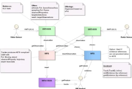
Figure 1 – Proposed Architecture (Simonis, 2011)
Within Figure 1 we see the core of the process is built around three services: an SOS for storing VMTI/GMTI data, a WPS for creating track data from the VMTI data and a WFS for storing the generated track data.
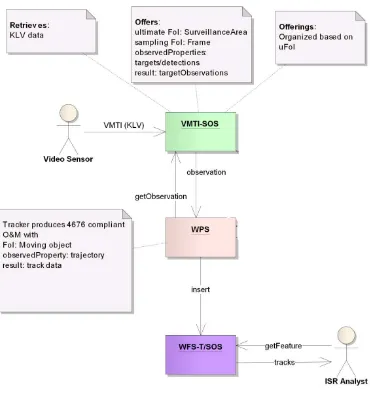
Figure 2 – Implemented Architecture
The VMTI SOS was implemented to support Observations and Measurements 2.0 and the new SWE set of standards. Observations were modeled using SWECommon.
The WPS implementation was designed to be invoked using direct references to the SOS GetObservation requests and WFS Transactions to extract target and motion imagery data, and to use this data to calculate tracks for moving objects and insert these objects into the WFS. The WPS was designed to be compliant with OGC WPS specification version 1.0.0.
Software clients were developed to subscribe for updated track features. These clients could be used to visualize the track geometries, associated track metadata and video frame evidence encoded in the track data.
In the process of implementing these components, some key points were brought to attention :
The PubSub / notification pattern can work, but requires further development. This will be addressed by the work of the PubSub working group of the OGC. Issues evolve around event patterns, clearly identifying event topics and message structures at the service level and delivery mechanisms for these events. During OWS-8 guidance was taken from work done in OWS-6, PubSub working group and WSN, but the ultimate implementation across services is a work in progress. Further development along these lines should be closely integrated with PubSub proposals as they become available.
STANAG 4676 can be represented using GML features in a WFS. Track generation can be accomplished using a WPS using stored target
detections and motion imagery from an SOS, however, real-world operations may cause a need to defer the use of the SOS until after tracks are generated. The tracker WPS is required to accumulate and store “evidence” metadata for
the generated tracks. This evidence can be referenced but not stored in the 4676 track data, pointing to a need for a standardized format that encompasses all types of evidence for tracks.
A number of shortcomings in the data set provided for the test bed caused a set of challenges for the tracking algorithm. These are discussed in detail in section 7.3.
The SOS standard may need to provide a way to directly access binary information like video data as observations.
The current architecture is not set up for real time delivery of track information. Bottle necks can occur in processing video data to the SOS and track production at the WPS.
6 SOS implementation
The SOS implementations for this sub-thread were aimed at providing Capabilities and Observation results based on the new SWE suite of protocols and service standards. These included SOS 2.0, SWE common and Observations and Measurements 2.0. The emphasis for these SOSes was on using a temporal filter for retrieving observations of frame, target and motion imagery directly as binary data such as mpegs or jpegs or as metadata expressed as SWE Common and O&M 2.0. The SOS was determined to be an adequate container for the data within the proposed concept of operations.
6.1 Available data sets
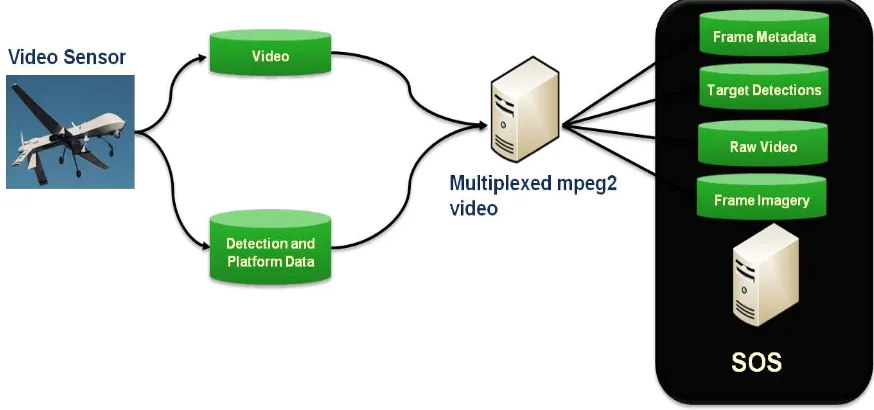
For OWS-8, experimental data was provided as two motion imagery files from the Australian DSTO. These files, in addition to video data, contained metadata multiplexed into the video stream according to MISB standards 0601.4 and EG0903.0. In order to accurately insert this data into the SOS, ingestion software was developed to parse the KLV encoded metadata from the data streams and insert the metadata into two offerings, one being frame metadata and the other being target metadata.
The ingestion software was built on the software packages xuggler and ffmpeg. Video data was parsed and packets on the metadata stream were identified as KLV. These packets were cross referenced with the corresponding MISB KLV encoding standards and inserted into a database designed to house the pertinent metadata properties. Four SOS offerings were created for each supplied video stream.
Figure 3 – Storage of Video Frame and Detection Information in SOS
Offerings are described in the sections tables below. Of importance to note is that the relevant and available data from each MISB dataset has been captured based on the data provided. Expansion of the offerings based on more sophisticated data should be part of future work. Some values were derived from the raw metadata. Derived values will be discussed.
6.2 The Frame offering
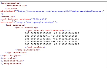
Table 1 – Frame Offering shows the observed properties available for this offering. In addition to each property presented in the table, two relevant properties required in an O&M observation are present for any observation from this offering: the phenomenon time which is derived from the frame timestamp and the sampling geometry which is derived from the latitude and longitude offsets from the frame center as in the following example.
Figure 4 – Example of Frame Polygon Sampling Feature
<om:parameter>
The sampling geometry is represented as an inline GML 3.2 Polygon of two dimensions. The representation could be improved to include altitude if an elevation model was available. It was decided to derive the polygon representation of the frame corners as this would aid selection by spatial filtering and provide a sampling geometry directly.
Because of this, the frame offsets were not retained because this was deemed to be redundant.
urn:misb:def:0601:Checksum N/A n Checksum
urn:misb:def:eg0903:FrameHeight Pixels n Frame Height
urn:misb:def:eg0903:FrameWidth Pixels n Frame Width
urn:misb:def:eg0903:NumberOfDetectedTargets N/A n Total Number of
Targets in the Frame
urn:misb:def:eg0903:NumberOfReportedTargets N/A n Number of Reported
Targets
urn:misb:def:eg0903:VMTILDSVersionNumber N/A n UAS LDS Version
Number
urn:misb:def:eg0903:VMTISensorHFOV Degrees n Sensor Horizontal
Field of View
urn:misb:def:eg0903:VMTISensorVFOV Degrees n Sensor Vertical Field
of View
urn:misb:def:eg0903:VMTISourceSensor Text n Source Sensor
Identifier
urn:misb:def:eg0903:VMTISystemName Text n VMTI System Name
urn:misb:def:eg0903:VideoFrameNumber N/A n Video Frame
Number
urn:misb:def:eg0903:FrameURL Text y N/A
The frame URL derived value is given an observed property urn which implies that it is from the 0903 dataset. This is not the case and another property definition should be developed.
An example observation request and response is located in .
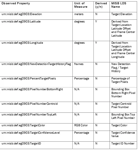
6.3 The TargetResult Offering
The TargetResult Offering was developed to support the geographical and frame location of target detections recorded in the target local data pack defined in MISB EG0903 (Motion Imagery Standards Board, 2009). These detections are essential for developing track information. These detections are used as a seed for deriving points along a track occupied by a moving object.
data samples lacked higher order information regarding the target pixel information. These properties were captured in the offering, but were not populated as the supporting data was not in the samples.
For the sampling geometry, a quadrilateral was chosen similar to the quadrilateral chosen for the frame offering. This was in anticipation of area target information and not just point target information. The resulting target geometry was always a polygon with no area. The value for this quadrilateral was calculated using the associated frame center Latitude and Longitude and target offset.
Table 2 – Target Result Offering
O
urn:misb:def:eg0903:Elevation meters N Target Elevation
urn:misb:def:eg0903:Latitude degrees Y Derived from
Target Location Latitude Offset and Frame Center Latitude
urn:misb:def:eg0903:Longitude degrees Y Derived from
Target Location Latitude Offset and Frame Center Longitude
urn:misb:def:eg0903:NewDetectionTargetHistoryFlag frames N New Detection
Flag / Target History
urn:misb:def:eg0903:PercentTargetPixels Percentage N Percentage of
Target Pixels
urn:misb:def:eg0903:PixelNumberBottomRight N/A N Bounding Box
Bottom Right Pixel Number
urn:misb:def:eg0903:PixelNumberCentroid N/A N Target Centroid
Pixel Number
urn:misb:def:eg0903:PixelNumberTopLeft N/A N Bounding Box Top
Left Pixel Number
urn:misb:def:eg0903:TargetColor RGB Color N Target Color
urn:misb:def:eg0903:TargetConfidenceLevel Percentage N Target Confidence
Value
urn:misb:def:eg0903:TargetIntensity Unused – for Infrared Systems
N Target Intensity
urn:misb:def:eg0903:TargetPriority N/A N Target Priority
One observed property that should have been included in the target offering was the frame number. Because the frame number was not explicitly included, cross-referencing targets to frames was done using time stamps. This was possible, but not ideal.
6.4 The Video Offering
The Video offering was designed to generate video clips defined by a temporal range filter. There are two typical uses for this offering. The first is that a tracker can request segments of video based on detection time ranges. Thus the tracker would not need to download the complete clip, but segments at a time. The second application was for clients to retrieve video evidence directly without needing to download O&M metadata, parse it and then retrieve the video clip using an embedded video link.
In OWS-8, the tracker made use of the video offering, but the presentation of the video data was imperfect and allowances had to be made in software to return the complete video stream. An ideal software implementation would present the video data accurately synched to frame number and timestamps in the detection data. Additionally, video clips would be multiplexed with the original VMTI metadata. Video clips were extracted and returned successfully, but no software library was found that would retain the VMTI metadata.
In addition to direct delivery of video data, the Video Offering presented an O&M response that contained a text result that was a URL to the video clip.
In future work, it is worth investigating the application of spatial filters to video observations that have spatial metadata associated with the frame information.
6.5 The Frame Image Offering
The Frame Image Offering was implemented as a method for retrieving a raw jpeg image for a frame from the motion imagery using a time instant temporal filter. This offering fulfilled the same functions as the video offering, but for a single frame. This offering was used by client software to retrieve video imagery, but was not used by the tracking algorithm.
7 WPS Tracker implementation
7.1 Tracker Algorithm
In order to turn raw video and VMTI detections into a moving object track, a processor, typically known as a tracker is involved. For OWS-8, this processor was implemented using the OGC WPS 1.0.0 specification (Yu & Chen, 2011). The algorithm for detection-to-track is based on the Kanade-Lucas-Tomasi feature tracker. All frames, not just the frames with metadata, must be retrieved together in order to better facilitate the
assumption of the tracking algorithm. The algorithm assumes that an object moves only slightly across frames. If there is a big "jump" of tracking object between frames, the algorithm would not work or easily lose the object under tracking. Once the feature is found in the target frame, the closest detection from the metadata is used in the track if there is one such detection point in the metadata that is not farther than 10 pixels in this case. KLT also supports multi-resolution tracking to deal with relatively large
displacements of targets between video frames. Affine computation was enabled with KLT to deal with non-consecutive frames. In the implementation, empirical adaptation and adjustment were supported to achieve best results of tracking in a geospatially-aware sense. These include enhancements for :
being adaptive to the size of target under investigation by defining the tracking target window size,
being capable of varied range of displacements by adaptively adjusting the parameters for multi-resolution / pyramid, and
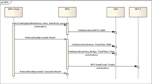
7.2 Tracker Inputs and Execution Sequence
The three SOS offerings used by the WPS were Frame, TargetResult and Video. These were defined as inputs to an instance of a WPS “Execute” request. An example of the
Figure 5 -- Tracker Inputs
Figure 6 -- WPS Sequence Diagram
The ultimate result of the tracking process as seen in the diagram is insertion of Track Data in a WFS. The nature of the Track features in the WFS is the subject of the next section.
7.3 Lessons learned and discussions
During the development and use of the tracking algorithm, a number of problems arose around the data that was available. What follows are discussions and recommendations based on these issues.
7.3.1 Target Characteristics and Algorithm Traceability Problems:
Features for extracting the detections in the video frames can be very useful at the stage of forming the tracks from detections. Here, detections are those points or locations where the targets are identified. The detections may be determined by some target-detecting algorithms.
can be useful information for tracking if these features and their deriving algorithm are known to the tracking algorithm.
These may not be an issue if the detection and tracking are done by the same party because they implicitly know what algorithm is used for extracting detection features and the nature of the information passed along. However, if the detection and the tracking are realized by different parties or at a different time, the knowledge of the algorithms and nature of the data is not traceable.
Tracking algorithms need to have some way to compare the similarity between detections across frames. Ideally, the tracking algorithm would require information of geometrical characteristics, radiometric characteristics, and algorithms for extracting these detections (no matter if the features are geometrical, radiometric, or hybrid features).
In the GMU Implementation of Detection-to-Tracking algorithm, the dimension of the target can be very a useful feature for KLT algorithm. The use of target dimension can be used in combination of KLT multi-resolution capability to enhance the accuracy of target tracking. However, the dimensions aren’t completely available to the algorithm.
Therefore, these are exposed as input parameters for the WPS. Ideally, these should be automatically extracted from the detection metadata.
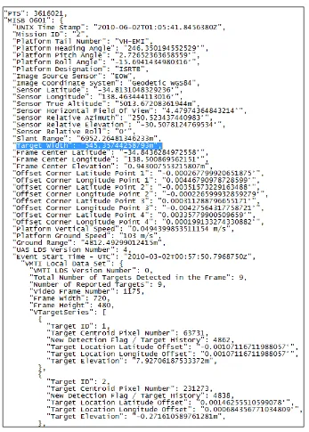
In MISB 0601, there is some target size information as shown in Figure 7 and Figure 8. However, these may not be properly tagged for all detections. Some detection has incomplete information or even none at all. Figure 9 shows one example that has target width.
Figure 7. Target width in MISB 0601
Figure 9. Target size information in one detection example
In the case of multiple moving targets occurring in the same frame, the scheme of MISB 0601 may not be sufficient in properly defining every target under tracking. One target may have a significantly different dimension from another in the same frame. So, the dimensions may have to be defined in each VMTI tag, or in MISB EG 0903.
Recommendations:
(1) MISB or NATO standards: Detection characteristics should be defined and described for any target under detections.
a. Add more geometrical/radiometric information model into MISB 0903 VMTI description or MISB 0601. Reference model may refer to ISO 19115.
b. Add algorithm information model provenance/lineage into MISB, including the detection algorithm used and the model to retrieve the detection features. Reference model may refer to ISO 19115-2.
c. Geometrical information model may be added to MISB 0903 at LDS for VMTI. This may be more relevant if there are multiple targets with different dimensions occurred in a single frame.
(2) OGC Informational Model: OGC information model should precisely model all the information available in MISB specifications.
a. Size and other geometrical metadata should be passed along to be modeled in the O&M of the SOS.
b. If the MISB provide expansion facility, the OGC information model should describe a similar mechanism to accommodate specific profiles or expansions.
7.3.2 Target Motion Metrics for Detections Problems:
Dead reckoning may be necessary in continuously moving target tracking. When a target moves along a road or path, it can be occluded by overhead coverage or below similar pavement to the color of target body. To keep track of the target, a momentum may be added to the target to estimate how far and in what direction the target will keep moving if the tracking algorithm loses sight of the target temporarily. In the GMU
implementation of Detection-to-Tracking WPS, a momentum is used to keep the target moving in the same direction and speed over the average of certain numbers of previous frames. This has been proved to be very useful in the case of tracking the vehicle moving across the bridge where the vehicle has a very similar tone to its background road surface. The KLT algorithm loses track of the target during these frames but eventually emerges after several frames. The added momentum solved the problem of losing the tracking target in this case.
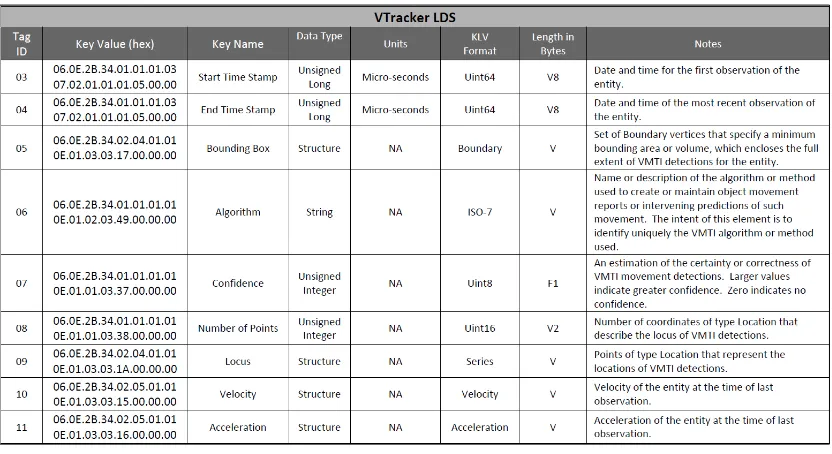
From this experience, it is obvious that motion metrics of the target under
at 70mph while special police car may move at a slightly faster speed, e.g. 80 mph on average. The general sense of speed may be useful in correcting the automatically derived speed from tracking algorithm.
In MISB 0903, velocity and acceleration are fields in the VTracker LDS as shown in Figure 10. However, the example dataset provided for use in the OWS-8 does not have any detection containing these fields.
Figure 10. Speed and acceleration tag in MISB 0903
Recommendations:
MISB standards and dataset for experiment:
(1) In MISB 0903 or 0601, extension may be added to support the description of the target as different types that have different range of speed/acceleration.
(2) Experiment dataset should have the info.
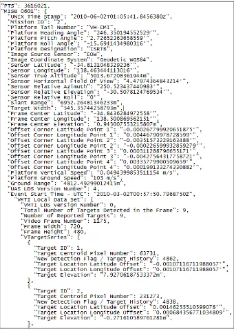
7.3.3 Sensor Metadata for Frame Co-Registration Problems:
In MISB 0601 specification, there are sensor angle and location information, also platform angle and location information. The example dataset does not have complete information for all the detections. Some detection has partial metadata as shown in Figure 11. Some does not have any at all.
Figure 11. Camera metadata of MISB 0601 in the example dataset
Recommendations:
MISB standards and datasets:
(1) VMTI dataset with complete camera position should be provided for testing. (2) OGC information model for modeling the MISB 0601 should have these metadata
encoded and made accessible through SOS.
7.3.4 Cross-referencing for Performance – Incremental Processing Problems:
Incremental processing should be enabled with the Detections-to-Tracks WPS.
Incremental processing should allow the instant processing of long video streams without delays or waiting until the whole video is available. The current implementation of the tracking WPS does not enable incremental processing. The reason is that exact cross-referencing of frame, metadata, and video is not possible with the current implementation of OGC Information Model in the SOS. The SOS only provides the frames and their metadata when such frames have metadata information. The SOS omits those frames that have no metadata. For example, Figure 13 shows the frame #2007 metadata retrievable from the SOS and Figure 12 shows the frame #2012 retrievable from the SOS. All frames between 2007 and 2012 do not have metadata and these frames cannot be retrieved from the SOS.
Figure 13. Frame 2007 retrieved from the SOS
Recommendations:
Cross-referencing of frame, frame metadata, and video segments should be enabled through the OGC Information model for VMTI data. For example, an updated frame number may be assigned. The number should be relevant to the video segment to be retrieved, if the same period is defined to retrieve frames, metadata, and video segment.
7.3.5 Accurate Target Detection for Performance – One Target One Detection Problems:
Recommendations:
The detection algorithm should generate the VMTI detections with the constraints that one target should have only one detection.
7.3.6 Multiple Target Detections for Performance – Moving Targets in Different Directions
Problems:
The example dataset has another special case that creates problems in tracking objects when two moving targets meet. The case is shown in Figure 15, Figure 16, and Figure 17. In Figure 15, two vehicles are tracked, labeled as vehicle A and B. They have detections described in VMTI. When the two vehicles are crossing each other, some frames have metadata for one vehicle but not both. In the frame shown in Figure 16, vehicle B has metadata but vehicle A does not. In the frame shown in Figure 17Figure 16, vehicle A has metadata but vehicle B does not. This inconsistency creates confusion for the tracking algorithm because both vehicles are so close in these frames. Both detections fall within the threshold of being assigned to either track. The tracking algorithm can easily assign the detection to wrong track.
Figure 15. Two vehicles under tracking
Figure 17. Another vehicle is detected and tagged in another adjacent frame although both vehicles present
Recommendations:
The VMTI dataset should label and provide all detections if multiple targets under tracking occurred in the same frame, Especially when targets occur in the same frame where targets are close together and move in different directions.
8 Web Feature Service implementation
NATO proposed a standard for transmitting and sharing track information; this standard is known as STANAG 4676. It defines a track as a set of associated state vector estimates describing the time-sequenced location, velocity, acceleration, and other relevant
characteristics of a mobile object or group of objects
For OWS-8, the tracking thread required a way to store and retrieve information modeled after the STANAG 4676 standard. We wanted the ability to store and retrieve both the current location of a detection, as well as the full path (track) of the same object.
8.1 Feature Type Implementations in the WFS
The STANAG 4676 UML model developed for OWS-8 (Simonis, 2011) features Tracks as a complex type, consisting of one or more TrackItem elements. A TrackItem could then be either a TrackInformation element or a TrackPoint element, each of which had their own complex types as sub-elements. In order to maintain a manageable feature type in the WFS, the data model was flattened as much as possible, leaving just track
The following table lists the fields available in STANAG 4676, and identifies which ones were included:
E
E lleemm eenn tt FFiieelldd nn aamm ee IInn cclluuddeedd ((yy//nn ))
TrackMessage messageSecurity Y
TrackMessage msgCreatedTime N
TrackMessage senderId N
TrackMessage stanagVersion N
Track exerciseIndicator Y
Track simulationIndicator Y
Track trackComment Y
Track trackNumber Y
Track trackSecurity Y
Track trackUUID Y
TrackItem itemComment Y
TrackItem itemSecurity Y
TrackItem itemSource Y
TrackItem itemTime Y
TrackItem itemUUID Y
TrackPoint displayPosition Y
TrackPoint objectMask Y
TrackPoint Source Y
TrackPoint Status Y
TrackPoint Type Y
TrackPointDetails covarianceMatrix N
TrackPointDetails Position Y
TrackPointDetails Velocity Y
E
E lleemm eenn tt FFiieelldd nn aamm ee IInn cclluuddeedd ((yy//nn ))
TrackIdentityInformation identificationSource N
TrackIdentityInformation Identity N
TrackIdentityInformation identityAmplification N
TrackIdentityInformation identityCredibilty N
TrackIdentityInformation iif_code N
TrackIdentityInformation unitName N
TrackIdentityInformation unitSymbol N
TrackClassificationInformation Classification Y
TrackClassificationInformation classificationCredibility N
TrackClassificationInformation classificationSource Y
TrackClassificationInformation Strength N
TrackManagementInformation alertIndicator N
TrackManagementInformation Environment N
TrackManagementInformation Quality N
TrackManagementInformation tracker_type N
TrackManagementInformation trackProductionArea Y
VideoInformation Band N
ESMInformation Agilty N
ESMInformation Modulation N
ESMInformation Power N
ESMInformation pulseRepetitionFreq N
ESMInformation Spectrum N
ESMInformation Staggered N
LineageRelation relatedTrackNumber N
LineageRelation relatedTrackUUID N
E
E lleemm eenn tt FFiieelldd nn aamm ee IInn cclluuddeedd ((yy//nn ))
LineageRelation Relation N
Table 3 -- STANAG 4676 Fields
8.1.1 Inserting Track Data
As the tracker was to consume data from the SOS and then insert features into the WFS, it was only necessary for the track to be inserted once, at the point of first detection. From that point on, track points could be inserted, but the parent track was only updated.
8.1.2 Updating Track Data
When additional SOS detections were available to the tracker, new track points were inserted into the WFS. Rather than require the tracker to also update the track with the new geometry information, the WFS service automatically updated with the latest geometry coming from the inserted track points.
A sample track point insert can be seen in A.7.
9 Notification Service implementation
As there was a need in the Tracking thread to be able to send notification messages regarding what was being tracked, Compusult’s WFS service had to be extended to provide “PubSub” (Publish/Subscribe) capabilities. As there was already an OGC PubSub working group, we attempted to follow guidelines that they were putting in place, although they are still working toward a final solution and thus we had to make our own implementation decisions.
9.1 OASIS Web Services Notification (WSN)
The OASIS WSN standard was chosen as the basis for our notification service as it provides a framework for subscriptions and notifications, and was under consideration by the OGC PubSub working group.
WSN defines Subscribe, Renew, and Notify requests and responses, which were used by our notification service and clients.
The WSN framework is flexible, allowing “Any” elements inside the XML requests to allow subscription filters to be based on any XML element. Unfortunately, “Any”
element also meant that it was easy to have XML that validates against the WSN schema, but that doesn’t match the format that the web service is expecting. As such,
communication outside of the schema provided by the web service to the client was required so that clients would be sending data in the expected format.
9.2 SubscriptionManager
It was easier to create a separate web service to act as the Subscription Manager on behalf of the Web Feature Service, at least until the PubSub operations are officially added into a future version of WFS.
9.2.1 Subscribe
A Subscribe request requires 3 pieces of information: 1. Where to send notifications (ConsumerReference) 2. What to subscribe to (Filter)
3. How long to subscribe for (InitialTerminationTime) A sample Subscribe request can be seen here:
<?xml version="1.0" encoding="UTF-8"?>
>http://ows-8.compusult.net/wes/Notification</Address> </ConsumerReference>
<?xml version="1.0" encoding="UTF-8"?>
Prior to a subscription expiring, a client can request that the subscription be extended by sending the following request:
9.2.3 Topics
The scenario called for objects to be tracked within a defined area of interest (AOI). Thus, two types of notification messages were expected: 1) notification that an object had entered or exited the area of interest; and 2) detections of the object as it moves within the area of interest.
Different clients would be interested in one of these two possible types of notification messages. The GeoSMS notification broker would want to be notified of objects that are entering the specified area of interest, and would then generate a GeoSMS message to their subscribed clients with a reference back to the original detection. A map client, on the other hand, would be interested in receiving all object data so that it can draw and track the object on a map as it moves within the area of interest.
To support different types of notifications, we made use of the concept of Topics. Topics were advertised to the clients by placing them inside the ExtendedCapabilities section of the WFS GetCapabilities response.
Clients that were interested in receiving “match” notifications (that is, an object matching the area of interest) could subscribe to the “Match” topic, or two either or both of the “EnterArea” and “ExitArea” subtopics.
Similarly, clients that were interested in receiving all data could subscribe to the “Transaction” topic, or to any or all of the “Insert”, “Update”, and “Delete” subtopics.
9.3 Notifications
Notification messages are generated by the WFS for any subscription that the Transaction satisfies.
9.3.1 Match
If the client specified the Match topic, they will receive a Notify message that includes geospatial information as well as the GetFeature request URL.
A sample match notification can be seen here: <?xml version="1.0" encoding="UTF-8"?>
xmlns:wfs-topic="http://www.opengis.net/wfs/topic"> wfs-topic:Match/wfs-topic:EnterArea
WFS request, which consists of the msgf:URIPath URL appended with the msgf:ExtendedParameters content.
9.3.2 Transaction
If the client specified the Transaction topic, they will receive a Notify message that includes full FeatureCollection information from the WFS.
A sample transaction notification can be seen here illustrating delete and update notifications:
xmlns:wfs-topic="http://www.opengis.net/wfs/topic"> wfs-topic:Transaction/wfs-topic:Delete
wfs-topic:Transaction/wfs-topic:Update
A map client can translate this FeatureCollection information into data that can be rendered as points and tracks on a map.
10 Client Implementation
10.1 Client Data Flows
For OWS-8, the scenario revolved around the concepts of subscription to track
information. The analyst user would subscribe for notifications of new track data. When these notifications were received, the analyst would be able to access the track data and visualize the data on the map. Once the track data was accessible, the analyst could use metadata to retrieve the imagery evidence provided in the track data and display track information directly on the imagery. This data flow was proven in concept. The following table provides the use case used for the OWS-8 demo.
Table 4 -- Use case for tracking and notification
Title Analyst Use Case for viewing track information
Description This use case illustrates the subscription for track data, display of track data in a mapping client, accessing the track metadata and retrieval of imagery evidence to illustrate and confirm the track information.
Actors: ISR analyst, UAV controller
Trigger: Earthquake occurs and tracking data is required for a bridge area to confirm or deny traffic flow.
Preconditions: WPS and client have access to WFS and SOS
of VMTI frame and detection information WPS is available to analyze data for tracks Notifications can be sent from WFS to client
Post conditions: Track data is displayed to the user
Track evidence is retrieved from the SOS and is displayed to the user
Basic Flow (Steps):
1. Analyst logs in to portal
2. Analyst requests UAV to survey area. 3. UAV is tasked to survey area.
4. UAV film is uploaded to SOS 5. WPS is invoked to create track data
6. Analyst discovers Track WFS using catalog.
7. Analyst subscribes to Track WFS by drawing area of interest on map.
8. WPS inserts discovered tracks into WFS 9. Client receives notification from WFS. 10. Client retrieves track data from WFS. 11. Client displays track data on the map.
12. Analyst invokes dialog to display track metadata for selected track.
13. Client displays imagery evidence retrieved from SOS. 14. Imagery evidence shows tracked object which is
highlighted using metadata retrieved from SOS. Notes None
Figure 20 -- Client use of services illustrates how the client software uses the WFS and the SOS to visualize tracking data. The user is provided with a dialog that displays track data from a WFS track point feature. The track point contains relevant metadata that can be used by an analyst. Additionally, the feature contains a link to the video evidence for that derived track point. It is important to note that the point has been developed from the detection and video information and will not have a direct correspondence to the
detections available from the SOS.
the client retrieves frame metadata such as footprint quadrilateral, frame height and width. These are used with track point geographic position to plot the track point on the frame image itself.
Because all track points are available from the WFS, the analyst can flip back and forth between frames and see the plotting of track points over frame imagery to determine the accuracy of the track and the visual properties of the tracked feature.
Figure 20 -- Client use of services
Figure 21 -- Track Display Using a WMS provides a screenshot of the analyst interface showing a track developing along a road. The dot indicates the latest known track point and the brown line indicates the known geometry of the track. Clicking on the track will invoke the dialog illustrated in Figure 22 -- Track Point Interface. In that figure, we can see frame imagery, metadata for the latest point and Next and Previous buttons that allow the Analyst to view track points, their metadata and associated frame imagery. The track point itself is plotted on the frame imagery. This is illustrated in Figure 23 --
10.2 GeoSMS notification
As part of OWS-8, notification was supported using a brokering system that would relay WFS notifications to mobile clients as GeoSMS messages. These messages would contain enough information to orient the receiver geographically and enable the receiver to retrieve track information directly from the WFS. In order to accomplish this, there are 2 stages in the notification process. The first is the registration of the client with the notification broker. The broker sits between the client (mobile device) and the
notification producer (WFS) and specializes in subscribing to the producer in a generic way, but relaying any notifications from the producer in a client-specific manner. In the OWS-8 scenario, the broker received data from the WFS in XML SOAP messages, but relayed the data as GeoSMS messages.
Figure 24 - Subscribing to a Broker
Figure 25 - Subscription from Broker to Subscription Manager
Figure 26 -- Notification Process
The process for registering with the broker and the subsequent WFS notifications is illustrated in Figure 26 -- Notification Process.
10.3 Mobile Client Implementation
Annex A
Example Requests and Responses
This Annex is designed to illustrate requests and responses used by components of the OWS-8 Observation Fusion Tracking sub-thread. Each request and response is labeled for cross-reference in the main body of this Engineering Report.
A.1 Sample SOS Frame GetObservation Request and Response
http://ows-<sos:GetObservationResponse xmlns="http://www.opengis.net/sos/2.0"
xmlns:sos="http://www.opengis.net/sos/2.0" xmlns:gml="http://www.opengis.net/gml/3.2"
xmlns:om="http://www.opengis.net/om/2.0" xmlns:swe="http://www.opengis.net/swe/2.0"
xmlns:swes="http://www.opengis.net/swes/2.0" xmlns:xlink="http://www.w3.org/1999/xlink"
xmlns:xsi="http://www.w3.org/2001/XMLSchema-instance"><observationData> <OM_Observation gml:id="226691" xmlns="http://www.opengis.net/om/2.0">
<om:type xlink:href="
http://www.opengis.net/def/observationType/OGC-OM/2.0/OM_Measurement"/><om:phenomenonTime><gml:TimeInstant
gml:id="phenomenontime226691">
<gml:timePosition>2010-06-02T01:05:52.613Z</gml:timePosition>
</gml:TimeInstant></om:phenomenonTime>
<om:resultTime xlink:href="#phenomenontime226691"/><om:procedure
xlink:href="urn:misb:def:0601:VideoSource4"/><om:parameter><om:NamedValue><om:name
xlink:href="http://www.opengis.net/req/omxml/2.0/data/samplingGeometry"/><om:value> <gml:Polygon srsName="EPSG:4326"
xmlns:gml="http://www.opengis.net/gml"><gml:exterior><gml:LinearRing><gml:posList
srsDimension="2">138.50555538051267 34.84308962838208 138.50178558162963 34.847340093789356 138.49644331654588 34.84412191696511 138.49990869329687 -34.84007516260859 138.50555538051267 -34.84308962838208
</gml:posList></gml:LinearRing></gml:exterior></gml:Polygon></om:value></om:NamedValue> </om:parameter>
<om:observedProperty xlink:href="urn:misb:def:0601:Checksum"/>
<om:observedProperty xlink:href="urn:misb:def:eg0903:FrameHeight"/>
<om:observedProperty xlink:href="urn:misb:def:eg0903:FrameWidth"/>
<om:observedProperty xlink:href="urn:misb:def:eg0903:NumberOfDetectedTargets"/>
<om:observedProperty xlink:href="urn:misb:def:eg0903:NumberOfReportedTargets"/>
<om:observedProperty xlink:href="urn:misb:def:eg0903:VMTILDSVersionNumber"/>
<om:observedProperty xlink:href="urn:misb:def:eg0903:VMTISensorHFOV"/>
<om:observedProperty xlink:href="urn:misb:def:eg0903:VMTISensorVFOV"/>
<om:observedProperty xlink:href="urn:misb:def:eg0903:FrameURL"/> <om:result>
<swe:DataRecord gml:id="226691"> <swe:field name="VMTI_CHECKSUM">
<swe:Quantity definition="urn:misb:def:0601:Checksum"> <swe:value>63576</swe:value>
</swe:Quantity> </swe:field>
<swe:field name="FRAME_HEIGHT">
<swe:Quantity definition="urn:misb:def:eg0903:FrameHeight"> <swe:value>480</swe:value>
<swe:uom code="pixels"/> </swe:Quantity>
</swe:field>
<swe:field name="FRAME_WIDTH">
<swe:Quantity definition="urn:misb:def:eg0903:FrameWidth"> <swe:value>720</swe:value>
<swe:uom code="pixels"/> </swe:Quantity>
</swe:field>
<swe:field name="NUMBER_OF_DETECTED_TARGETS">
<swe:Quantity definition="urn:misb:def:eg0903:NumberOfDetectedTargets">
<swe:value>1</swe:value> </swe:Quantity>
</swe:field>
<swe:field name="NUMBER_OF_REPORTED_TARGETS">
<swe:Quantity definition="urn:misb:def:eg0903:NumberOfReportedTargets">
<swe:value>1</swe:value> </swe:Quantity>
</swe:field>
<swe:field name="VMTI_LDS_VERSION_NUMBER">
<swe:Quantity definition="urn:misb:def:eg0903:VMTILDSVersionNumber">
<swe:value>0</swe:value> </swe:Quantity>
</swe:field>
<swe:field name="VMTI_SENSOR_HFOV">
<swe:Quantity definition="urn:misb:def:eg0903:VMTISensorHFOV">
<swe:value>4.47974</swe:value> <swe:uom code="degrees"/> </swe:Quantity>
</swe:field>
<swe:field name="VMTI_SENSOR_VFOV">
<swe:Quantity definition="urn:misb:def:eg0903:VMTISensorVFOV">
<swe:value>null</swe:value> <swe:uom code="degrees"/> </swe:Quantity>
</swe:field>
<swe:field name="VMTI_SOURCE_SENSOR">
<swe:Text definition="urn:misb:def:eg0903:VMTISourceSensor">
<swe:value>EOW</swe:value> </swe:Text>
</swe:field>
<swe:field name="VMTI_SYSTEM_NAME">
<swe:Text definition="urn:misb:def:eg0903:VMTISystemName"> <swe:value>null</swe:value>
</swe:Text> </swe:field>
<swe:field name="VIDEO_FRAME_NUMBER">
<swe:Quantity definition="urn:misb:def:eg0903:VideoFrameNumber">
<swe:value>1499</swe:value> </swe:Quantity>
</swe:field>
<swe:field name="FRAME_URL">
http://ows-</swe:DataRecord>
A.2 Sample SOS Target GetObservation Request and Response
<?xml version="1.0" encoding="UTF-8"?><sos:GetObservationResponse
xmlns="http://www.opengis.net/sos/2.0" xmlns:sos="http://www.opengis.net/sos/2.0"
xmlns:gml="http://www.opengis.net/gml/3.2" xmlns:om="http://www.opengis.net/om/2.0"
xmlns:swe="http://www.opengis.net/swe/2.0" xmlns:swes="http://www.opengis.net/swes/2.0"
xmlns:xlink="http://www.w3.org/1999/xlink" xmlns:xsi=" http://www.w3.org/2001/XMLSchema-instance"><observationData>
<OM_Observation gml:id="226692" xmlns="http://www.opengis.net/om/2.0" >
<om:type xlink:href="
http://www.opengis.net/def/observationType/OGC-OM/2.0/OM_Measurement"/><om:phenomenonTime><gml:TimeInstant
gml:id="phenomenontime226692">
<gml:timePosition>2010-06-02T01:05:52.613Z</gml:timePosition>
</gml:TimeInstant></om:phenomenonTime>
<om:resultTime xlink:href="#phenomenontime226692" /><om:procedure
xlink:href="urn:misb:def:eg0903:VMTIDetector3" /><om:parameter><om:NamedValue><om:name
xlink:href="http://www.opengis.net/req/omxml/2.0/data/samplingGeometry"/><om:value> <gml:Polygon srsName="EPSG:4326"
xmlns:gml="http://www.opengis.net/gml"><gml:exterior><gml:LinearRing><gml:posList
srsDimension="2">138.50075870634086 34.845127318294544 138.50075870634086 34.845127318294544 138.50075870634086 34.845127318294544 138.50075870634086 -34.845127318294544
</gml:posList></gml:LinearRing></gml:exterior></gml:Polygon></om:value> </om:NamedValue>
</om:parameter>
<om:observedProperty xlink:href="urn:misb:def:eg0903:Elevation" />
<om:observedProperty xlink:href="urn:misb:def:eg0903:Latitude" />
<om:observedProperty xlink:href="urn:misb:def:eg0903:Longitude" />
<om:observedProperty xlink:href="urn:misb:def:eg0903:NewDetectionTargetHistoryFlag" />
<om:observedProperty xlink:href="urn:misb:def:eg0903:PercentTargetPixels" />
<om:observedProperty xlink:href="urn:misb:def:eg0903:PixelNumberBottomRight" />
<om:observedProperty xlink:href="urn:misb:def:eg0903:PixelNumberCentroid" />
<om:observedProperty xlink:href="urn:misb:def:eg0903:PixelNumberTopLeft" />
<om:observedProperty xlink:href="urn:misb:def:eg0903:TargetColor" />
<om:observedProperty xlink:href="urn:misb:def:eg0903:TargetConfidenceLevel" />
<om:observedProperty xlink:href="urn:misb:def:eg0903:TargetID" />
<om:observedProperty xlink:href="urn:misb:def:eg0903:TargetIntensity" />
<om:observedProperty xlink:href="urn:misb:def:eg0903:TargetPriority" />
<om:result>
<swe:DataRecord gml:id="226692"> <swe:field name="ELEVATION">
<swe:Quantity definition="urn:misb:def:eg0903:Elevation"> <swe:value>null</swe:value>
<swe:uom code="meters" /> </swe:Quantity>
</swe:field>
<swe:field name="LATITUDE">
<swe:Quantity definition="urn:misb:def:eg0903:Latitude"> <swe:value>-34.845127</swe:value>
</swe:Quantity> </swe:field>
<swe:field name="LONGITUDE">
<swe:Quantity definition="urn:misb:def:eg0903:Longitude"> <swe:value>138.500759</swe:value>
<swe:uom code="degrees" /> </swe:Quantity>
</swe:field>
<swe:field name="NEW_DETECTION_TARGET_HISTORY">
<swe:Quantity definition="urn:misb:def:eg0903:NewDetectionTargetHistoryFlag">
<swe:value>5307</swe:value> <swe:uom code="frames" /> </swe:Quantity>
</swe:field>
<swe:field name="PERCENT_TARGET_PIXELS">
<swe:Quantity definition="urn:misb:def:eg0903:PercentTargetPixels">
<swe:value>null</swe:value> </swe:Quantity>
</swe:field>
<swe:field name="PIXEL_NUMBER_BOTTOM_RIGHT">
<swe:Quantity definition="urn:misb:def:eg0903:PixelNumberBottomRight">
<swe:value>null</swe:value> </swe:Quantity>
</swe:field>
<swe:field name="PIXEL_NUMBER_CENTROID">
<swe:Quantity definition="urn:misb:def:eg0903:PixelNumberCentroid">
<swe:value>120778</swe:value> </swe:Quantity>
</swe:field>
<swe:field name="PIXEL_NUMBER_TOP_LEFT">
<swe:Quantity definition="urn:misb:def:eg0903:PixelNumberTopLeft">
<swe:value>null</swe:value> </swe:Quantity>
</swe:field>
<swe:field name="TARGET_COLOR">
<swe:Quantity definition="urn:misb:def:eg0903:TargetColor"> <swe:value>null</swe:value>
</swe:Quantity> </swe:field>
<swe:field name="TARGET_CONFIDENCE_LEVEL">
<swe:Quantity definition="urn:misb:def:eg0903:TargetConfidenceLevel">
<swe:value>null</swe:value> </swe:Quantity>
</swe:field>
<swe:field name="TARGET_ID">
<swe:Quantity definition="urn:misb:def:eg0903:TargetID"> <swe:value>1</swe:value>
</swe:Quantity> </swe:field>
<swe:field name="TARGET_INTENSITY">
<swe:Quantity definition="urn:misb:def:eg0903:TargetIntensity">
<swe:value>null</swe:value> </swe:Quantity>
</swe:field>
<swe:field name="TARGET_PRIORITY">
<swe:Quantity definition="urn:misb:def:eg0903:TargetPriority">
<?xml version="1.0" encoding="UTF-8"?>
<wps:Execute service="WPS" version="1.0.0" xmlns:wps="http://www.opengis.net/wps/1.0.0"
xmlns:ows="http://www.opengis.net/ows/1.1" xmlns:xlink="http://www.w3.org/1999/xlink"
xmlns:xsi="http://www.w3.org/2001/XMLSchema-instance"
<ows:Identifier>frames</ows:Identifier> <wps:Reference mimeType="application/xml"
schema="http://schemas.opengis.net/sos/1.0.0/sosGetObservation.xsd"
xlink:href="
http://ows-<ows:Identifier>detections</ows:Identifier> <wps:Reference mimeType="application/xml"
schema=http://schemas.opengis.net/sos/1.0.0/sosGetObservation.xsd
<ows:Identifier>video</ows:Identifier> <wps:Reference mimeType="video/avi"
schema="http://schemas.opengis.net/sos/1.0.0/sosGetObservation.xsd"
xlink:href="
http://ows-<ows:Identifier>parameters</ows:Identifier> <wps:Data>
<wps:ComplexData mimeType="application/xml"
schema="http://ws.laits.gmu.edu/tracksparameters.xsd"> <tp:TracksParameters
xmlns:tp="http://ws.laits.gmu.edu/tracksparameters"