Comparison of Galerkin-type discretization
techniques for two-phase flow in heterogeneous
porous media
Rainer Helmig* & Ralf Huber
Institut fu¨r Wasserbau, Universita¨t Stuttgart, Pfaffenwaldring 61, 70569 Stuttgart, Germany
(Received 1 October 1996; revised 15 May 1997; accepted 7 July 1997)
A comparison of Standard Galerkin, Petrov–Galerkin, and Fully-Upwind Galerkin methods for the simulation of two-phase flow in heterogeneous porous media is presented. On the basis of the coupled pressure–saturation equations, a generalized formulation for all three finite element methods is derived and analysed. For flow in homogeneous media, the Petrov–Galerkin method gives excellent results. But this method fails miserably for problems with heterogeneous media. This is because it is not able to capture correctly processes that take place at interfaces when, for instance, the capillary pressure–saturation relationship after Brooks and Corey is assumed. The Fully-Upwind Galerkin method is superior to the Petrov–Galerkin approach because it is able to give correct results for flow in homogeneous and heterogeneous media for the two models of van Genuchten and Brooks–Corey. The widely used dpc/dSwgrad Swformulation which is correct for the homogeneous case cannot be used for heterogeneous media. Instead the straightforward approach of grad pcin combination with a chord-slope technique must be utilized.q1998 Elsevier Science Limited. All rights reserved
Key words: multiphase flow, finite element method, heterogeneous porous media, capillary effects.
1 INTRODUCTION
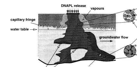
Groundwater contamination by dense non-aqueous phase liquids (DNAPL) such as chlorinated solvents, PCB, and creosote is widespread throughout industrialized areas of Europe and North America. DNAPL have low viscosities and are significantly more dense than water, allowing them to migrate to great depths below the water table. Once present in the subsurface, residual and pooled DNAPL will slowly dissolve into flowing groundwater, giving rise to aqueous phase contamination. Fig. 1 presents a general schematic DNAPL distribution in the subsurface following a release from the ground surface. The liquid phase contaminant leaves behind a trail of immobile resi-dual as it migrates through unsaturated and saturated media. This residual acts as a long-term source of contami-nation to both the air and water phase.
Recent laboratory and field experiments, as well as
observations at accidental spill sites, have demonstrated that the infiltration and remobilization of DNAPL is strongly influenced by porous media heterogeneity (e.g., Kobus et al.,1 Kueper and Frind,2and Pankow and Cherry3).
In recent years, a number of numerical models have been developed to simulate the migration of DNAPL through porous media. Standard upstream techniques can be employed in models using a finite difference discretization. Upstream weighted test functions have been derived for use with finite element discretizations (e.g. Abriola and Pinder,4 Faust et al.,5 Forsyth,6 Helmig,7 Huyakorn and Pinder,8 Kueper and Frind,9 Pruess,10 Sleep and Sykes,11 and Unger et al.12). The use of the majority of these models has been limited to contaminant migration in homogeneous media with very few applications to heterogeneous media systems. For completeness, another class of discretization methods based on mixed finite elements13,14 should be mentioned. These methods are suitable for heterogeneity problems, but they have one
Printed in Great Britain. All rights reserved 0309-1708/98/$19.00 + 0.00
PII: S 0 3 0 9 - 1 7 0 8 ( 9 7 ) 0 0 0 2 3 - 7
697
severe disadvantage: since these methods employ an IMPES approach, strong capillary effects cannot be accounted for in an adequate way.15
To investigate the influence of heterogeneities, we will consider a case of two-phase flow: one wetting and one non-wetting fluid phase, where flow is perpendicular to an interface between regions of different permeability and porosity. In particular, we will focus on the conditions to be posed at interfaces across which the permeability and porosity, and subsequently the constitutive laws which are described by them, are discontinuous.
The objective of this paper is to derive a generalized formulation for Standard Galerkin, Petrov–Galerkin and Fully-Upwind Galerkin finite element methods based on the coupled pressure–saturation formulation16 and to address the different discretizations by simulation of DNAPL migration through heterogeneous porous media. In order to illustrate that completely different results are possible for the same problem using Standard Galerkin, Petrov-Galerkin and Fully-Upwind Galerkin finite element methods, different mathematical formulations were applied to (1) a one-dimensional vertical example with two different capillary pressure–saturation relation-ships, one after Brooks–Corey and one after van Genuchten, and (2) a two-dimensional controlled laboratory vertical sand pack experiment.
2 GOVERNING EQUATIONS
Multiphase flow in porous media is described by Darcy’s law and the continuity equation for each fluid phase. The Darcy velocity for phaseais given by
where pais the phase pressure, krathe relative permeability,
ma the dynamic viscosity, ̺a the density, K the intrinsic permeability tensor, and g the gravitational acceleration vector. Subscripts w and n denote the wetting phase and
the non-wetting phase, respectively. The mobility la of each phase a is then defined as the ratio of the relative permeability krato the dynamic viscosityma.
The continuity equation for incompressible two-phase flow in porous media is given by
](fraSa)
]t ¼ ¹=·[rana]þraqa,a[{w,n} (2)
where Sais the saturation and qarepresents the volumetric source rate of phase a. Porosityf is assumed constant in time.
In addition to Eq. (1) and eqn (2), the following relationships must also be satisfied
kra¼kra Sa ÿ ,
a[{w,n} (3)
pc¼pc Sw
ÿ
¼pn¹pw (4)
SwþSn¼1 (5)
It should be noted that the constitutive relationships for capillary pressure and relative permeability are strongly non-linear functions of the saturations.
Substituting eqn (1), eqn (4), and eqn (5) into eqn (2) yields, after some modifications, the coupled pressure– saturation formulation for incompressible two-phase flow with unknowns pwand Sn
¹f]Sn
]t ¼=· lwK· =pw¹rwg
ÿ
þqw
f]Sn
]t ¼=· lnK· =pwþ=pc¹rng
ÿ
þqn (6)
If the entire domain is single phase, then the system of equations reduces to a parabolic equation with respect to the fluid pressure. On the other hand, if we consider one-dimensional flow with zero capillary pressure, the coupled equations eqn (6) are reduced to the well-known Buckley–Leverett equation which represents a non-linear hyperbolic equation with respect to the fluid saturation.16 (1)
Therefore, we regard pressure as a ‘parabolic-type’ and saturation as a ‘hyperbolic-type’ variable.17 Hence, this system of equations can be classified as a mixed hyper-bolic–parabolic type.
Many formulations substitute dpc/dSwgrad Swfor grad pc(e.g., Morgan et al.
18
). The resulting system of equations differs from eqn (6) with respect to the second equation which is then
In the next sections we will discuss the influence of these two numerical approximations with different discretization techniques.
3 DISCRETIZATION
We now seek to derive a generalized formulation for Standard Galerkin (SG), Petrov–Galerkin (PG), and Fully-Upwind Galerkin (FUG) finite element methods based on the coupled pressure–saturation equations eqn (6). The weak form of this coupled pressure–saturation formulation can be expressed as
Z
is the Neumann boundary volumetric flux term for each phasea,n is the outward unit normal to boundary~ G, and
dan represents the Kronecker delta. The integral equations
are weighted by test functions Wiwhich are only non-zero
over elements having node i.
Eqn (8) represents the basis for our further investigations. For the unknown pressure and saturation, continuous piece-wise linear approximations are chosen which have the following representation
where Ni are the base functions of the corresponding
approximation space with the property Ni¼dij at node j;
the hat values are the values of the approximation at the corresponding nodes. The permeability tensor, the porosity, the relative permeability, and the capillary pressure functions are defined at nodes. For the discretization in time, an implicit Euler scheme is used. Replacing pw, pc
and Sn in eqn (8) by their approximations, eqn (9), and
using the identity for the gravitational acceleration
g¼gD¼gXiDˆiNiwhere D is the depth and g the gravity wherehiis the set of neighbour nodes connected to node i.
Two subscripts are added to the mobilities la indicating which test and shape functions are involved where la appears. We will incorporate all three discretization methods into one general formulation. To achieve this, the terms representing the process vectors in eqn (8) are reformulated. Since = XjNj
¼0, the following equali-ties are valid
In all three methods, the mass lumping technique is applied. The mass matrix of the accumulation term on the left-hand side of eqn (10) is modified in the following manner. The diagonal coefficients of the mass lumped matrix Mlump are the sums of all coefficients of the corresponding row, and all off-diagonal coefficients are zero, i.e.
Mlumpij ¼dij
X
k[i
where
Mik¼
Z
QWiNkdQ
The diagonalized lumped matrix coefficients are then
Miilump¼
Z
QWidQ¼ : Vi (13)
Reformulating the discretized equations using eqn (10) and eqn (12) gives
In the dpc/dSw=Swformulation, the difference of the nodal
capillary pressure values pˆnc,þj1¹pˆ values of pressure and gravity in the integral terms above are constants, the equations are reduced to
fVi
For homogeneous media, the permeability tensor K is constant over the entire domain. At interfaces between zones of different rock properties, K is harmonically weighted. We apply now the influence coefficient tech-nique19,6to all three discretization methods, characterized
by the following approximation
wherelAa,ij¼l(S),¯ S being the saturation at some specific¯ point in the intersection of the support of Wa,iand Nj. A and B are introduced as general superscripts indicating the
choice of discretization for the mobility termlaand trans-missivity integral (transmissibility) ga, respectively. Sub-stitution of Eq. (16) into eqn (15) yields the following generalized Galerkin finite element formulation
(¹1)dawf ˆSnþ1 In contrast to the generalized Galerkin finite element repre-sentation in eqn (17) for the =pc formulation, the integral
terms of the dpc/dSw=Swformulation are evaluated using a
four-point Gauss quadrature rule.
For the different discretization methods we will demon-strate that, in general, upstream weighting improves the front approximation for homogeneous media. However, not all choices of upstream weighting guarantee the correct physical behaviour of the numerical solution.
The different discretizations of the mobility term and transmissivity integral are now presented, illustrated, and discussed.
3.1 Standard Galerkin method (SG)
The SG method is characterized by the same choice for (linear) test and shape functions, i.e. Wi¼ Ni. Under the
assumption of a linear approximation of the mobility la over each element, the mobility term is arithmetically weighted, resulting in
lSGa,ij¼ 1
2(la,iþla,j), a[{w,n} (19)
For capillary diffusion dominated processes, this method works quite well. However, when convection becomes dominant, it is well-known that the use of arithmetically averaged mobilities as it is done by SG renders the scheme unstable and produces oscillating non-physical solu-tions.16,8
3.2 Petrov–Galerkin method (PG)
In order to ensure convergence of the numerical solution, a modified Petrov–Galerkin method was devel-oped in which the test functions are up to two polynomial degrees higher than the shape function.7,20,21We consider the case of piecewise quadratic test functions in one dimension having the following representation for an ele-ment (xi, xj) upwind parametera˜a,i for theaphase equation is defined by
wherewa,i andwa,j are evaluated at the previous iteration
step. The use of a two-point Gaussian quadrature rule with Gauss points at xiþ1=2ð16ð1= following weighting of the nodal mobilities
lPGa,ij¼ 7 6la,i¹
1
6la,j (22)
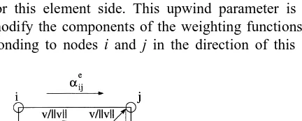
in the case that node i is the upstream node for phasea. Consequently, in this case the mobility term lPGa,ij is par-tially upstream weighted. The PG method coincides with the SG method in the case when a˜a¼0. Analogously to the development of modified upwind weighting functions for linear one-dimensional elements, it is possible to derive polynomials for bi- and tri-linear elements in two and three dimensions, respectively.7In order to avoid artificial cross diffusion in multidimensional problems, the upwind para-metersa˜ are calculated from the streamlines. Fig. 2 illus-trates this for the derivation of parameter a˜eij between nodes i and j of a rectangular element e. The velocity is evaluated at the two nearest Gauss points with respect to an element side. The two velocity vectors are normalized and projected to this element side. Consequently, the value of higher magnitude is selected as the upwind parameter for this element side. This upwind parameter is used to modify the components of the weighting functions corres-ponding to nodes i and j in the direction of this element
side. This method ensures that the residual of this ele-ment is weighted in the upstream direction. The extension to arbitrary quadrilateral elements is straightforward.
3.3 Fully-upwind Galerkin method (FUG)
Since Wi¼Niholds for both methods, the Fully-Upwind
Galerkin and the Standard Galerkin method, the respective transmissivity integrals are the same. For FUG, the mobility is fully upstream weighted, and it is equal to the value of the mobility at the upstream node, i.e.
lFUGa,ij ¼
It is also valid for the multidimensional case. In the one-dimensional case gij,(iÞ j), is always positive. However,
when discretizing a two-dimensional domain of interest, obtuse triangles and rectangles with a side length ratio of greater than p2 should be avoided, since they lead to negative transmissibilities gij which give rise to
non-physical discrete fluxes and can cause an oscillatory behaviour in the Newton iteration (Positive Transmissi-bility Condition22). A similar argument holds for the three-dimensional case. Because the Fully-Upwind Galerkin method uses a single-point quadrature rule to compute the integrals, it entails much less computational effort than the Petrov–Galerkin method which requires four Gauss points.
Equation (17) in combination with a Standard Galerkin discretization represents a type of finite volume formulation. A fully upwind scheme utilizing the above formulation is called a Fully Upwind Control Volume Finite Element (FU-CVFE) method.6 The Fully-Upwind Galerkin method (FUG) satisfies these conditions and subsequently belongs to this class of discretization methods (see e.g. Helmig23).
4 DISCUSSION OF TWO-PHASE FLOW IN HETEROGENEOUS MEDIA
Primary variables that show discontinuities at heterogene-ities are responsible for severe numerical difficulties. To illustrate this we will look at one-dimensional two-phase flow at the interfaces of two sands having different perme-abilities and porosities. The example considers flow in a porous medium structured into zones of coarse high perme-able sand (sand I) and fine low permeperme-able sand (sand II). The flow problem described by finite element formulation, eqn (8), requires two conditions for the transition from one sand to the other. The first condition is derived from the continuity equation and states that the flux from one side over an interface is equal to the influx over this inter-face into the other side, i.e.
QIaþQIIa¼0, a[{w,n} (24) Fig. 2. Petrov–Galerkin method: Upwind coefficients in two
The second condition comes from the continuity of ‘inten-sive’ physical quantities, e.g. pressure. But this constraint is only valid for mobile phase pressures. Thus, capillary pressure is continuous across the interface of a hetero-geneity, unless one phase is immobile on one side. Only if both phases are mobile on each side of the heterogeneity interface does the following equality hold
pIc¼p II
c (25)
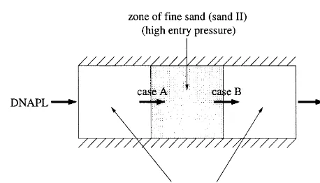
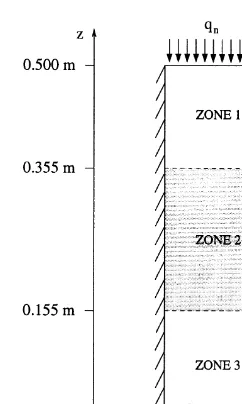
Consider the one-dimensional displacement of a wetting phase (water) by a non-wetting phase (DNAPL-dense non-aqueous phase liquid) through a porous medium divided into three zones (Fig. 3) where zones 1 and 3 con-sist of sand I and zone 2 of sand II.
At the two interfaces of the configuration different processes take place. At the left interface the non-wetting phase passes a transition from coarse sand to fine sand which we refer to as case A. At the right interface the transi-tion occurs in the other directransi-tion from fine sand to coarse sand (case B).
It is possible to express capillary pressure as a function of permeability, porosity, and the J-Leverett function24 in the following way
pc¼j
f k
r
J(Sw) (26)
where j is the interfacial tension and k the (scalar) intrinsic permeability. The square root term reflects the mean pore diameter, and the J-Leverett function depends on the saturation and represents the lithology of the porous medium. Appropriate models of pc versus Sw are
the ones of Brooks and Corey (BC)25 and van Genuchten (VG).26
The capillary pressure–saturation function of Brooks and Corey is given by
pc¼PdS
¹1
l
e (27)
where
Se¼
Sw¹Swr
1¹Swr
is the effective saturation, Swr the wetting phase residual
saturation, and l the pore size distribution index of the corresponding sand. The model for the capillary pres-sure–saturation relationship of Brooks and Corey assigns a characteristic value, the so-called entry or bubbling pres-sure Pd, to each sand. Pdis the capillary pressure required
for a non-wetting fluid phase to displace a wetting fluid phase inside the corresponding sand (see the solid curves in Fig. 4). The material data of sand I and II are listed in Table 1. The lower curve corresponds to the coarse sand (sand I), the upper curve to the fine sand (sand II).
Consequently for case A (at the left interface) the non-wetting phase is unable to enter the low permeability zone until the capillary pressure at the interface is greater than or equal to the specified entry pressure. This can only occur when the non-wetting phase saturation has increased up to a certain value Sp
n¼1¹Spwwhere the capillary pressure is
Fig. 3. Displacement of water by DNAPL within a heterogeneous
medium.
Fig. 4. Capillary pressure–saturation curves.
Table 1. Material properties and model parameters
Unit Sand I Sand II
Intrinsic permeability K m2 5·04·10–10 5·26·10–11
Porosity f – 0·40 0·39
Wett. phase res. saturation Swr – 0·08 0·10
Non-wett. phase res. saturation Snr – 0·00 0·00
BC: entry pressure Pd Pa 370 1324
BC: pore size distribution index l – 3·86 2·49
VG: a Pa-1 0·0023 0·0006
equal to the entry pressure (Fig. 4), i.e.
pc Spw
ÿ
¼PdII (28)
As a consequence, the non-wetting phase is dammed up at the interface until the entry condition above is satisfied. At interfaces where case A occurs, discontinuities in the saturation appear.
At the second interface (case B) the transition is from fine to coarse sand. In contrast to case A, no accumulation of the non-wetting phase takes place. This is because the capillary pressure at the interface is greater than the entry pressure of zone 3. As in case A, a jump in the saturation develops at the interface. This jump is caused by a ‘sucking’ effect from the zone of fine sand into the zone of coarse sand. The non-wetting phase saturation level within the fine sand zone is higher than in coarse sand.
In contrast to the Brooks–Corey model, van Genuchten’s capillary pressure–saturation curves are continuous (Fig. 4). They are given by the following equation
pc¼
and n. Eqn (29) shows that ais inversely proportional to
Pd, the entry pressure of BC. The pore size distribution is
taken into account by parameter n. While low values of n (i.e. n→1) indicate soils with broad pore size distributions, higher n-values point to more uniform distributions.
Remark:
The main difference between the two models lies in the way they account for entry pressure effects. For water
saturation values close to one, the van Genuchten model gives a very small capillary pressure which converges for increasing Swto zero. The model of Brooks and Corey with
non-zero entry pressure Pdyields, in contrast to the other
model, values close to the entry pressure, which in some cases is of significant magnitude. In the van Genuchten approach, for any saturation on one side of the interface, there exists a corresponding saturation on the other side such that the capillary pressure is continous. If, however, for the Brooks–Corey approach the entry pressure is non-zero, in Fig. 4 (solid line) it can be seen that there is a specific saturation Sp
w such that continuity of capillary
pressure can only be achieved if the wetting phase saturation on the side corresponding to the lower curve is below or equal to Sp
w.
Lenhard et al.27 investigated the relationship between these two formulations and derived a formula to convert the parameters of one model into parameters of the other model. The pore size distribution index of the Brooks– Corey model is derived in the following manner
l¼(n¹1) 1¹S˜
where S˜e is selected as the medium effective saturation
within the range of Se. The entry pressure Pd of the
Brooks–Corey model is obtained by
Pd¼
where S˜x is a match-point effective wetting phase satura-tion, i.e. a value of Sefor which the pc–Swcurves of the two
models are closest to each other for a selected norm. Since the relative permeability–saturation curves of the two models are essentially the same we will not consider them for our investigations.
5 COMPARISON OF THE DIFFERENT DISCRETIZATIONS
The ability of the previously introduced Galerkin finite ele-ment discretizations to describe flow in heterogeneous media, especially at interfaces, will now be investigated.
For the Brooks–Corey model, we define the total poten-tial of the non-wetting phase at node i by
This formulation is compatible with the extended pressure condition (see e.g. van Duijn28) which states that capillary pressure must be continuous across an interface unless the non-wetting phase is immobile on the low permeability side. The non-wetting phase pressure is undefined if it is immo-bile. Hence pc ¼pn¹pwis not meaningful and does not
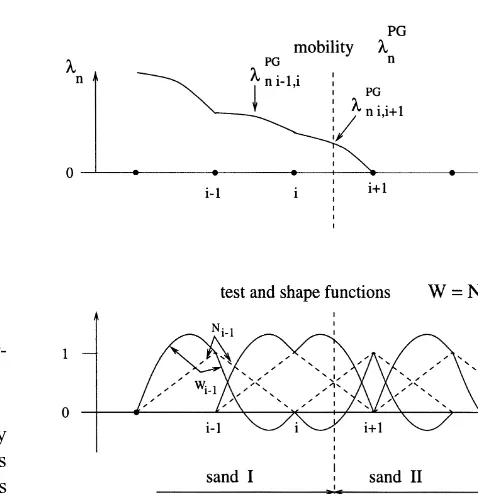
need to be continuous. Using for the BC model, eqn (32) instead of eqn (18) with eqn (4), we can define (wn,j¹wn,i) at an interface which constitutes a discontinuity in material properties within the porous medium. When at such a heterogeneity interface (wn,j¹wn,i), i denoting the upstream node, is negative, the entry pressure has not yet been achieved (see Fig. 5). However, if it becomes positive, the entry pressure has been achieved and an influx of the non-wetting phase into the low permeability zone takes place.
The discretizations for each method are graphically presented in Fig. 6, Fig. 7 and Fig. 8. The lower illustrations show the test and shape functions for each method. As mentioned in the previous section, the Standard Galerkin and Fully-Upwind Galerkin methods employ the same (piecewise linear) test and shape functions. In contrast, PG uses quadratic weighting functions (eqn (20)). In the upper illustrations, the discretized mobility of the non-wetting phase is presented for the situation when the non-wetting phase has reached the interface to the low perme-ability zone and the capillary pressure is smaller than the entry pressure.
The following statements can be derived from Figs. 5–8:
• At node i (see Fig. 5) the gradients of the non-wetting phase total potential wn as defined by eqn (18) and eqn (32), respectively, are opposite for all three discretizations, i.e.
wn,i¹wn,i¹1,0 andwn,iþ1¹wn,i.0 (33)
• Because physical properties are specified at nodes, an element having nodes which belong to different permeability zones can be considered as a transition element. For the Standard Galerkin method, the mobility of the non-wetting phase within this tran-sition element is non-zero. (wn,iþ1 ¹ wn,i) at the Fig. 5. Total potential of a non-wetting phase reaching an
inter-face with a transition to a zone with a higher entry pressure.
Fig. 6. Standard Galerkin discretization for a non-wetting phase at
an interface constituting case A.
Fig. 7. Petrov–Galerkin discretization for a non-wetting phase at
an interface constituting case A.
Fig. 8. Fully-Upwind Galerkin discretization for a non-wetting
interface within the transition element is positive (Fig. 5). Since the discrete phase flow is propor-tional to the product of phase mobility la and (wn,iþ1 ¹ wn,i), the Standard Galerkin method
produces a flow of the non-wetting phase from node iþ 1 to node i although at node i þ 1 the non-wetting phase is immobile or not present (Sn¼
0). This non-physical process produces a peak of the non-wetting phase saturation distribution at node i and probably a negative saturation at node
iþ1. The saturation level at the interface necessary for penetration of the non-wetting phase into the low permeability zone is achieved, at the same rate, or, sooner than it would be for the physical solution, because of an unphysical flow. This gives numerical results where the non-wetting phase reaches the entry pressure and enters a low permeability lens although physically this does not happen. The scheme implies a continuous distribu-tion of the saturadistribu-tion at the interface which yields in the case of the Brooks–Corey model a discontinu-ous approximation of the capillary pressure.
• The test function of the Petrov–Galerkin method for the non-wetting phase equation at node i is simi-lar to the one for the Standard Galerkin method because the gradients ofwnat this node are opposite (Fig. 7). Thus the problems arising with the Petrov– Galerkin approach are comparable to the ones with the Standard Galerkin method.
• Because the Fully-Upwind Galerkin method uses the fully upstream value of the mobility (as defined in eqn (23)), a flow of the non-wetting phase across the interface will not occur unless the pressure at the interface has reached the entry pressure. No unphysical flow occurs that could produce oscilla-tions in the numerical solution. At the interface,
mobilities are approximated discontinuously, the capillary pressure continuously.
To solve the system of non-linear equations eqn (17) for the corresponding discretization methods, a residual-based Newton–Raphson iterative concept is used.
6 NUMERICAL EXAMPLES
6.1 1-D problem in a homogeneous medium without capillary effects
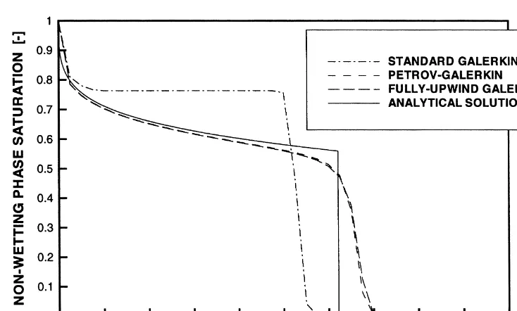
First we will show the performance of SG, PG, and FUG, with respect to flow in a homogeneous medium. The Buckley–Leverett problem29 is a simple test problem without capillary pressure effects whose analytical solution is easily found and which is excellent for investigating the resolution of discontinuities for each method.
A non-wetting phase displaces a wetting phase from left to right. The initial total velocity of the two-phase system, defined as the sum of the phase Darcy velocities, is 1·0 m s¹1, the ratio of the dynamic viscosities is one, residual saturations are zero and the Brooks–Corey function (l ¼
2·0) is used for the relative permeabilities. A space–time discretization ofDx¼0·025 m andDt¼0·005 s is chosen. Fig. 9 shows the saturation profiles at time t¼0·4 s for the three methods and the analytical solution. The SG method does not converge to the analytical solution because only numerical schemes using a form of upwind technique are able to capture correctly convection-dominated processes.30
6.2 1-D problem in a heterogeneous medium with capillary effects
between two layers of a coarse high permeable sand is used to verify how well these methods simulate multiphase flow in heterogeneous media (Fig. 10).
Table 1 shows the material properties and the parameters for each model used in the following simulations. The van Genuchten parameters are obtained by using the conversion formulas of Lenhard et al.27(eqn (30) and eqn (31)).
DNAPL infiltrates at the upper boundary with a flow rate of 0·005 kg s¹1. The densities and dynamic viscosities are
̺n ¼ 1400 kg m¹3, mn ¼ 0·001 kg (ms)¹1 for the non-wetting phase (DNAPL), and ̺w ¼ 1000 kg m¹3, mw ¼
0·001 kg (ms)¹1 for water. The discretizations used are
Dz¼0·01 m, andDt ¼5 s.
The entry pressure of Pd¼1324 Pa of the low permeable
layer corresponds to a saturation of Sp
n ¼ 0·91. Thus, the
physically correct solution shows a peak in the saturation above the heterogeneity of exactly this value.
First we take the dpc/dSw grad Swformulation which is
widely used in combination with constitutive relation-ships after Brooks and Corey.18For this formulation FUG produces an accumulation of the non-wetting phase satura-tion at the node above the heterogeneity, but Newton’s method fails to converge when the entry pressure is approached (Fig. 11 (c)). In contrast to FUG, SG and PG produce a numerical solution (see Fig. 11 (a),(b)); however the results do not consider the effect of the entry pressures and therefore do not correspond to the physically correct solution.
Now we consider the grad pc-scheme according to
eqn (17). For the Fully-Upwind Galerkin method, a damming-up of the non-wetting phase above the low per-meability lens is observed (Fig. 12 (c)). A penetration into the second layer starts when a saturation of 0·78 is reached at the node above the heterogeneity. However, the theo-retical value of saturation Sn necessary for penetration is
0·91, i.e. when the entry pressure is achieved. This value
is only a limit value for an infinitesimal reference volume. When refining the discretization the nodal value of Sn at
which the penetration starts converges to the value of 0·91, which is required by the entry pressure condition. Thus, the numerical scheme describes the physical process in an accurate manner. At the second transition, a constant flux of the non-wetting phase occurs. The saturation value at Fig. 10. Flow through a vertical column with a low permeability
layer (zone 2).
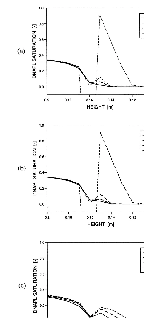
Fig. 11. Case A: DNAPL saturation at the interface for
(a) Standard Galerkin, (b) Petrov–Galerkin, (c) Fully-Upwind Galerkin, using dpc/dSw grad Sw formulation with Brooks–
the node upstream of the transition stays fixed at a relative small level of approximately 0·06. The mobility of this node saturation in conjunction with the pressure gradient over the transition element which also approaches a fixed value controls the flux (Fig. 13 (c)). In zone 3, which has the same material properties as zone 1, the same saturation level occurs.
In contrast to FUG, SG and PG are unable to capture the
physical process at the heterogeneity interface as discussed in the previous section. The coupling of the gradient ofwn
and mobilitylndoes not work for these two methods. The non-wetting phase becomes mobile within the transition element (for case A) and the gradient of wn points in the opposite direction of phase flow. This yields a non-physical flux from the downstream node to the upstream node. Consequently, negative saturations develop on the low Fig. 12. Case A: DNAPL saturation at the interface for
(a) Standard Galerkin, (b) Petrov–Galerkin, (c) Fully-Upwind Galerkin, using grad pcformulation with Brooks–Corey model.
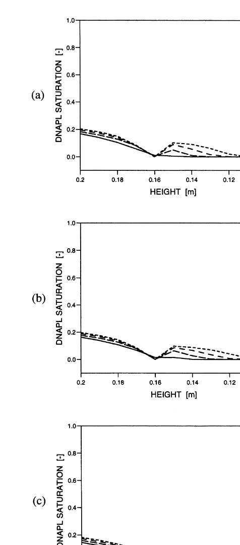
Fig. 13. Case B: DNAPL saturation at the interface for
permeability side of the interface. On the other side of the interface, the entry pressure is achieved within two time steps (Fig. 12 (a), (b)). The level of 0·91 is reached independently of the discretization lengths used. Negative saturations develop for both methods, SG and PG.
But we are still interested in the behaviour of these two methods, which have obviously been disqualified at the first interface, i.e. for case A, at the second transition constituting
case B. Here, a steep gradient of the non-wetting phase pressure causes a massive flux of non-wetting phase across this interface (Fig. 13 (a), (b)). Because mobilities are averaged over both nodes of the transition element, negative saturations develop ahead of the interface. While on the other side, the node saturation stays fixed at 0·91. This unphysical flux is a direct consequence of a non-zero (not full-upstream-weighted) mobility at the transition element, Fig. 14. Case A: DNAPL saturation at the interface for
(a) Standard Galerkin, (b) Petrov–Galerkin, (c) Fully-Upwind Galerkin, using grad pcformulation with van Genuchten model.
Fig. 15. Case B: DNAPL saturation at the interface for
and cannot be fixed in the case of PG through the employ-ment of the grad pc-chord-slope technique.
Computing the same problem with van Genuchten parameters yields the correct solution for all three methods. The van Genuchten model gives no strict entry condition. A small amount of non-wetting phase reaches the fine sand side. Because the capillary pressure–saturation curve for sand II is considerably steeper than for sand I in the vicinity of 1¹Snr, this causes a rapid increase in capillary pressure on the fine sand side. The Newton-type iterative scheme converges for all three methods and for all time-steps to solutions with monotone pressure distributions. A damming-up of the non-wetting phase at the interface up to a certain value takes place. In less technical and more mathematical terms, this phenomenon can be explained by the fact that when using the van Genuchten model the derivative of pc with respect to Snis very large near zero Sn. As a consequence, diffusion terms become dominant,
making this problem essentially parabolic; hence SG methods work.
From Fig. 12 and Fig. 14, it is apparent that the entry pressure of the van Genuchten model and the corresponding entry pressure Pdof the Brooks–Corey model result in the
same accumulation of the non-wetting phase and subse-quently must be the same. A massive flux across the inter-face starts when the non-wetting phase has dammed up in front of the interface and as this entry pressure of the van Genuchten model is approached (Fig. 14). When using the van Genuchten model, all three methods describe correctly the flow process at the transition from fine to coarse sand (case B). The corresponding numerical results are depicted in Fig. 15.
6.3 2-D problem in a heterogeneous medium
The 2D problem in a heterogeneous medium is a simula-tion of an experiment held at the VEGAS facility of the Institut fu¨r Wasserbau, University of Stuttgart.31 A con-tainer (0·65 m 3 0·30 m 3 0·90 m) was filled with two
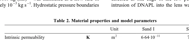
kinds of sand and saturated with water (Fig. 16). The low permeability lens (fine sand) measured 52·5 cm in length and 13·75 cm in height and was located 18·75 cm below the infiltration zone. The properties of the sands are listed in Table 2. Tetrachloroethylene (TCE), a DNAPL with a density of ̺n ¼ 1460 kg m¹3 and a dynamic viscosity
ofmn¼0·0009 kg (ms)¹1was infiltrated at a flow rate of approximately 10¹3kg s¹1. Hydrostatic pressure boundaries
were maintained at the left and right sides of the container. At 28 points within the container, probes were installed to detect the presence of DNAPL during the course of the experiment. For the simulation, a rectangular mesh with discretization lengths of
Dx¼
0:525=24 m if 0:1875 m,x,0:7125 m
0:1875=8 m otherwise (
Dz¼
0:325=8 m if z,0:325 m
0:1375=8 m if 0:325 m,z,0:4625 m
0:1875=8 m if z.0:4625 m 8
> > <
> > :
and time steps of 40 s is used.
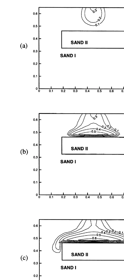
Fig. 17 and Fig. 18 show the numerical results for PG and FUG 1000 s, 3000 s, and 5000 s after the infiltration had started. Both methods simulate correctly the propagation of DNAPL within sand I. However, upon reaching the low permeability lens, DNAPL penetrates under the PG discre-tization, while under the FUG discretization it does not. DNAPL dams up above the lens and spreads out in the horizontal direction until DNAPL has reached the edge of the lens. Then the DNAPL front propagates down the sides of the low permeability block. In the experiment, it took approximately 1500 s for the infiltrated DNAPL to reach the lens (see Fig. 16). After another 500 s DNAPL was detected at one edge of the low permeability block. No intrusion of DNAPL into the lens was observed. But flow Fig. 16. Reconstruction of experimental result after 1000 s,
3000 s, and 5000 s, based on arrival times at probes.
Table 2. Material properties and model parameters
Unit Sand I Sand II
Intrinsic permeability K m2 6·64·10–11 7·15·10–12
Porosity f – 0·40 0·39
Wett. phase res. saturation Swr – 0·09 0·12
Non-wett. phase res. saturation Snr – 0.00 0·00
BC: entry pressure Pd Pa 755 2060
paths have developed in sand I, especially along the lens, resulting in sooner arrival times at some probes and later arrival times at other probes. Taking these phenomena into account, the numerical result obtained by the Fully-Upwind Galerkin method is in fair agreement with the experimental data (Fig. 16). As in the 1-D example (Fig. 11 (b)), the result of the Petrov–Galerkin method shows an unphysical flux of DNAPL into the lens.
7 CONCLUSIONS
The comparison in this paper has shown that the Petrov– Galerkin method and the Fully-Upwind Galerkin method
produce numerical solutions which accurately simulate two-phase flow in homogeneous media. The Standard Galerkin method is only able to give correct numerical solutions for diffusion-dominant processes. It has been shown that Standard and Petrov–Galerkin methods produce unphysical solutions for heterogeneous problems with non-zero entry pressures. For heterogeneous media, the numerical evaluation of the capillary pressure gradients together with a full upstream weighting of mobilities becomes crucial. Methods based on the dpc/dSw grad Sw
formulations either generate solutions which do not con-sider the effect of the entry pressures,16 or the Newton-type iteration scheme fails to converge. Evaluating grad Fig. 17. Result of Petrov–Galerkin method (dpc/dSw grad Sw)
after (a) 1000 s, (b) 3000 s, (c) 5000 s.
pc as the difference in the capillary pressures at discrete
nodes and fully upstream weighted mobilities leads to a discretization which is able to simulate multiphase flow at heterogeneities. The Fully-Upwind Galerkin method has proved to give correct results, even if capillary pressure– saturation curves have no continuous transition from single-phase (Sw¼1) to multiphase (Sw,1), for example
when the model of Brooks and Corey is assumed.
ACKNOWLEDGEMENTS
Funding for the research described in this article was provided by Deutsche Forschungsgemeinschaft, SFB 404 ‘Mehrfeldprobleme in der Kontinuumsmechanik’, and the scholarship for the second author by the foundation ‘Besinnung und Ordnung’. The authors thank Peter Bastian and Hussam Sheta for the helpful comments and construc-tive criticisms. In addition, we would like to thank the reviewers of this paper for their helpful comments.
REFERENCES
1. Kobus, H., Barczewski, B. and Koschitzky, K.-P. (editors), Groundwater and Subsurface Remediation. Environm. Eng., Springer Verlag, Berlin, 1996.
2. Kueper, B. H. & Frind, E. O., Two-phase flow in hetero-geneous porous media, 2. Model application. Water Resour. Res., 1991, 6(27), 1058–1070.
3. Pankow, J. F. and Cherry, J. A. (eds.), Dense Chlorinated Solvents and other DNAPLs in Groundwater. Waterloo Press, Waterloo, 1996.
4. Abriola, L. M. & Pinder, G. F., A multiphase approach to the modeling of porous media contamination by organic com-pounds, 2. Numerical simulation. Water Resour., 1985,
1(21), 1–26.
5. Faust, C. R., Guswa, J. H. and Mercer, J.W., Simulation of three-dimensional flow of immiscible fluids within and below the unsaturated zone. Water Resour. Res., 1989, 12(25), 2446–2464.
6. Forsyth, P. A., A control volume finite element approach to NAPL groundwater contamination. SIAM J. Sci. Stat. Comp., 1991, 12, 1029–1057.
7. Helmig, R., Theorie und Numerik der Mehrphasenstro¨-mungen in geklu¨ftet-poro¨sen Medien. Bericht Nr. 34, Inst. f. Stro¨mungsmechanik und Elektron. Rechnen im Bauwesen, Univ. Hannover, 1993.
8. Huyakorn, P. S. and Pinder, G. F., A new finite element technique for the solution of two-phase flow through porous media. Water Resour. Res., 1978, 1(5).
9. Kueper, B. H. and Frind, E. O., Two-phase flow in hetero-geneous porous media, 1. Model development. Water Resour. Res., 1991, 6(27), 1049–1057.
10. Pruess, K., TOUGH 2, A General-Purpose Numerical Simulator for Multiphase Fluid and Heat Flow. Lawrence Berkeley Laboratory, University of California, 1991. 11. Sleep, B. and Sykes, J. F., Compositional simulation of
groundwater contamination by organic compounds, 2. Model application. Water Resour. Res., 1993, 6(29), 1709–1718.
12. Unger, A. J. A., Forsyth, P. A. and Sudicky, E. A., Variable spatial and temporal weighting schemes for use in multi-phase compositional problems. Adv. in Water Res., 1996,
19(1), 1–27.
13. Chavent, G. and Jaffre, J., Mathematical models and Finite Elements for Reservoir Simulation. Vol. 17, Studies in Mathematics and Applications, Elsevier, 1986.
14. Chavent, G., Jaffre, J. and Roberts, J. E., Mixed-hybrid finite elements and cell-centered finite volumes for two-phase flow in porous media. In Mathematical Modelling of Flow through Porous Media, ed.A.P. Bourget, C. Carasso, S. Luckhaus and A. Mikelic. World Scientific, 1995, pp. 100-114.
15. Huber, R. and Helmig, R., Multiphase flow in heterogeneous porous media: a classical finite element method versus an IMPES-based mixed FE/FV approach. Submitted to Intern. J. for Num. Methods in Fluids.
16. Aziz, K. and Settari, A., Petroleum Reservoir Simulation. Applied Science Publ., London, 1979.
17. Helmig, R., Emmert, M. and Sheta, H., Modelling of multi-phase flow in heterogeneous porous media and applications. Proc. of 6th Int. Conf. on Computing in Civil and Building Eng., Berlin, A.A. Balkema, 1995.
18. Morgan, K., Lewis, R. W. and Roberts, P. M., Solution of two-phase flow problems in porous media via an alternating-direction finite element method. Appl. Math. Modelling, 1984, 8, 391–396.
19. Dalen, V., Simplified finite-element models for reservoir flow problems. SPE Journal, 1979, 333-343.
20. Helmig, R., Modelling multiphase flow in discrete fracture systems with a finite element method. Proc. of the IAHR/ AIRH Symposium on Transport and Reactive Processes in Aquifers, Zu¨rich, 1994.
21. Huyakorn, P. S. and Pinder, G.F., Computational Methods in Subsurface Flow. Academic Press, London, 1983.
22. Letniowski, F. W. and Forsyth, P. A., A control-volume finite element method for three-dimensional NAPL groundwater contamination. Intern. J. for Num. Methods in Fluids, 1991,
13, 955–970.
23. Helmig, R., Multiphase Flow and Transport Processes in the Subsurface-A Contribution to the Modeling of Hydrosystems-. EnvironmHydrosystems-. EngHydrosystems-., Springer, Berlin, 1997Hydrosystems-.
24. Leverett, M.C. Capillary behavior in porous solids. TAIME, 1941, 142, 152–169.
25. Brooks, R. H. and Corey, A.T., Hydraulic Properties of Porous Media. Hydrol. Pap., Vol. 3, Colorado State Univ., Fort Collins, 1964.
26. van Genuchten, M. T., A closed-form equation for predicting the hydraulic conductivity of unsaturated soils. Soil Sci. Soc. Am. J., 1980, 44, 892–898.
27. Lenhard, R. J., Parker, J. C. and Mishra, S., On the corres-pondence between Brooks-Corey and van Genuchten models. Journal of Irrig. and Drainage Eng., 1989, 115(4), 744–751. 28. van Duijn, C. J., Molenaar, J. and de Neef, M. J., Effects of capillary forces on immiscible two-phase flow in strongly heterogeneous porous media. Transport in Porous Media, 1995, 21, 71–93.
29. Buckley, S. E. and Leverett, M. C., Mechanism of Fluid Displacements in Sands. TAIME, 1942, 146, 107–116. 30. Sammon, P. H., An analysis of upstream differencing. SPE
Res. Eng. J., 1988, Aug., 1053–1056.