DIGITAL ELEVATION MODELS AND DERIVED PRODUCTS FROM LROC NAC
STEREO OBSERVATIONS
K.N. Burnsa, E.J. Speyerera, M.S. Robinsona, T. Trana, M.R. Rosiekb, B. A. Archinalb, E. Howington-Krausb and the LROC Science Team
a
School of Earth and Space Exploration, Arizona State University, 1100 S Cady, Tempe AZ 85287 – ([email protected])
b Astrogeology Science Center, United States Geological Survey, 2255 N Gemini Dr, Flagstaff AZ 86001 –(mrosiek, barchinal, ahowington)@usgs.gov
Commission IV, WG IV/7
KEY WORDS: DEM/DTM, Three-dimensional, Application, Planetary, Mapping, Geomorphology, Modeling, Processing
ABSTRACT:
One of the primary objectives of the Lunar Reconnaissance Orbiter Camera (LROC) is to acquire stereo observations with the Narrow Angle Camera (NAC) to enable production of high resolution digital elevation models (DEMs). This work describes the processes and techniques used in reducing the NAC stereo observations to DEMs through a combination of USGS integrated Software for Imagers and Spectrometers (ISIS) and SOCET SET from BAE Systems by a team at Arizona State University (ASU). LROC Science Operations Center personnel have thus far reduced 130 stereo observations to DEMs of more than 130 stereo pairs for 11 Constellation Program (CxP) sites and 53 other regions of scientific interest. The NAC DEM spatial sampling is typically 2 meters, and the vertical precision is 1-2 meters. Such high resolution provides the three-dimensional view of the lunar surface required for site selection, hazard avoidance and planning traverses that minimize resource consumption. In addition to exploration analysis, geologists can measure parameters such as elevation, slope, and volume to place constraints on composition and geologic history. The NAC DEMs are released and archived through NASA’s Planetary Data System.
1. INTRODUCTION
1.1 LROC
The Lunar Reconnaissance Orbiter Camera (LROC) consists of two narrow angle cameras (NACs) to provide 0.5 – 2.0 meter-scale panchromatic images of a 5km swath and a wide-angle camera (WAC) to provide images at a pixel-scale of 100 meters in seven color bands over a 60km swath (Robinson et al. 2010). The NAC was not designed as a stereo system, but obtains stereo pairs through images acquired from two orbits, with the spacecraft making at least one off-nadir slew (Figure 1). Stereo observations are nominally obtained on consecutive orbits in order to minimize lighting changes between observations. Slewing the spacecraft off-nadir interferes with data collection from other instruments, so LROC slew opportunities are limited to four per 24 hour period. Slew angles range between 0° and 30° and a convergence angle between images is typically between 10° and 45°.
1.2 DEM Production
This paper describes the production and release of NAC DEMs produced by the ASU team. However, NAC DEM production is carried out at various other institutions affiliated with the LROC team, including U.S. Geological Survey (USGS), NASA Ames, Jet Propulsion Laboratory (JPL), University of Arizona (UA), Ohio State University (OSU), and the German Aerospace Center (DLR) (Cohen et al. 2008). ASU, USGS, NASA Ames, and UA all use SOCET SET from BAE Systems (DeVenecia et al. 2007) for photogrammetric processing of NAC images. NASA Ames is using their Stereo Pipeline (Moratto et al. 2010) and OSU is using their Orbital Mapper and Leica Photogrammetry Suite 9.3. DLR uses photogrammetry software developed in-house (Oberst et al. 2010).
2. DATA SOURCES
Figure 1. Diagram Illustrating NAC stereo image acquisition.
2.1 LROC NAC
The LROC NACs are linear pushbroom cameras built using the Kodak KLI-5001G line array. The line array is a 5064 element charge coupled device (CCD) with 7-micron pixels. The two NAC cameras are designated Left (L) and NAC-Right (NAC-R). The NACs are mounted on the spacecraft such that the CCDs are perpendicular to the spacecraft’s X-axis. Each camera is designed to provide 0.5 meter pixel scale panchromatic images covering a 2.5 km swath cross-track, for a combined coverage of 5 km, at an altitude of 50 km. Each camera has an internal buffer of 256MB; allowing for an image length of 52,224 lines or 26,112 meters at the native resolution.
The NAC images are sampled at 12 bits and companded (e.g. compressed) to 8 bits. Each camera has a field of view of 2.86°, which are mounted to overlap by approximately 135 pixels in the cross-track direction and are offset from each other by ~185 pixels in the down-track direction (Robinson et al. 2010).
Stereo images are collected by acquiring images on two different orbits so that the convergence angle is between 10° and 45°. The overlap between the two NAC-L and NAC-R images provides three or four stereo models from which to collect elevation data. The number of models depends on the orientation of the images and how they intersect one another. The amount of overlap and the actual footprint are affected by the topography and acquisition parameters such as center latitude, center longitude, and slew angle.
2.2 LOLA
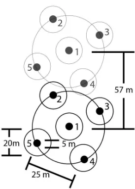
Figure 2. LOLA spot pattern (Smith et al. 2010).
Altimetry obtained from the Lunar Orbiter Laser Altimeter (LOLA) is used to increase the absolute accuracy of NAC DEMs. LOLA was designed to measure the shape of the Moon by precisely measuring the range from the spacecraft to the surface, and incorporating precision orbit determination of LRO by referencing surface ranges to the Moon’s center of mass. Its primary objective is to produce a global geodetic grid for the Moon to which all other observations can be precisely referenced (Smith et al. 2010). LOLA is a pulse detection time-of-flight altimeter that incorporates a five-spot pattern to measure the precise distance to the surface at 5 spots simultaneously, thus providing 5 profiles for each orbit. LOLA fires at a fixed, 28 Hz rate, so that for a nominal 1600 m/s ground track velocity, there is one shot approximately every 57 meters. At a nominal 50 km altitude, each spot within the five-spot pattern has a diameter of 5 meters while each detector field of view has diameter of 20 meters. The spots are 25 meters apart and form a cross pattern canted by 26° counter-clockwise to provide five adjacent profiles (Figure 2) (Smith et al. 2010, Zuber et al. 2010). The LOLA instrument boresight is aligned with the LROC NAC cameras to enable altimetry collection in the overlap region between NAC-L and NAC-R. By using Earth-based laser ranging tracking and crossover analysis the accuracy of the LOLA dataset is improved.
3. METHODOLOGY
To produce DEMs of key regions of interest (see workflow in Figure 4), Integrated Software for Image and Spectrometers (ISIS; http://isis.astrogeology.usgs.gov/index.html; Anderson, et al., 2004) routines ingest the images, perform a radiometric correction, and export the image data in SOCET SET format. The NAC files imported into SOCET SET are radiometrically corrected images and contain a list of keywords of relevant parameters regarding the spacecraft position and pointing.
SOCET SET includes a push broom sensor model that has been adapted to handle many spacecraft cameras (including LROC NAC) that is used to relate the image space to ground coordinates. A bundle adjustment is performed on the images to correct for offsets in camera pointing using a multi-sensor triangulation (MST) algorithm. MST is used to update camera pointing, improve registration between areas of stereo coverage, and ground truth using tie-points, sensor position, and camera pointing. Tie points relate a point in the overlapping area of two or more images, while ground points register a point or identifiable object in the image to a point on the ground. Selected parameters, such as the position, velocity, and pointing angles of the cameras are adjusted so that the root mean square (RMS) errors for all the tie point measurements are minimized. Stereo pairs can be mosaicked together by placing tie points in areas of stereo coverage (Figure 3). Mosaicking stereo pairs tends to increase the overall RMS error when applying a bundle adjustment to the sets of images, revealing the presence of unmodeled systematic errors. For example, in images with minimal change in slew angle during image acquisition, the offset between image sets is less than 1 meter. When spacecraft maneuvers do not maintain a constant slew angle during image acquisition (which can be quite irregular and may not be well modeled by the adjusted parameters), the offsets can vary between 3 m to 15 m.
Figure 3. Color shaded relief terrain model derived from a NAC DEM mosaic of 13 stereo pairs of Lichtenberg Crater. The enlargements display color shaded terrain, slope map, and orthophoto derived from the DEM mosaic.
To improve absolute accuracy between the images, LOLA altimetric profiles are used to define the geodetic reference frame for the DEMs. The images are shifted in relation to their original latitude, longitude, scale, elevation, and horizontal and vertical rotation, using a script in MATLAB, in order to better fit the LOLA data.
Once the images are adequately registered to each other, as well as the LOLA data, the process of extracting DEMs can begin with NGATE (SOCET SET- Next Generation Automatic Terrain Extraction). NGATE performs image correlation and edge matching for every pixel in the image to create a dense model. The DEM is then resampled to at least three times the ground sampling distance of the image in order to reduce noise. In the nominal phase of the mission (50 km circular orbit) DEMs were typically sampled at a two meter pixel scale. Results from NGATE require very little editing if the stereo pair was acquired under nominal conditions (35° to 65° incidence angle and 10° to 45° convergence angle). Low incidence angles can cause LROC images to be difficult to co-register between images while images with a high incidence angle are significantly affected by shadows and thus require extensive editing. NGATE is not optimized to work with the linear pushbroom images. In order to increase effectiveness, a pair-wise rectification is performed on the images used for DEM extraction. Pair-wise rectification rotates the images so that the epipolar lines are horizontal and scales are set to a common pixel scale. The rectified images make stereovision easier on the analyst, and are required for the accurate generation of the DEM (Tran et al. 2010).
Figure 4. Workflow diagram for DEM production.
Orthorectified images are created upon completion of the DEM using SOCET SET’s Orthophoto Generation. Orthophotos are images that have had all distortion due to camera obliquity and terrain relief removed. An orthophoto represents what you would see if you were looking at the ground orthogonally from a distance above (every pixel is viewed as if nadir). In addition, a hill shade image, color shaded relief image, slope map, and confidence map are provided in GeoTIFF format. These products are made using the Geospatial Data Abstraction Library (GDAL) (Warmerdam 2008).
4. ERROR ANLAYSIS
The overall quality of the DEM is a measurement of both the absolute and relative accuracies. The absolute accuracies are determined by how far the coordinates of the DEM align with the true latitude and longitude. LOLA altimetry provides the absolute geodetic reference frame for the NAC DEMs. A crossover correction analysis with the LOLA data shows improvement in the RMS differences between the LOLA track data to 10.18 m along track, 8.37 m cross track, and 1.8 m radially (Mazarico et al 2011). On average then, it can be expected that the positional accuracy of LOLA data approaches these levels.
4.1 Relative Error
The theoretical expected vertical precision of NAC DEMs can be calculated based on the spacecraft orbit and camera geometry. While acquiring stereo images, the spacecraft is either pointed nadir or rolled about the flight line. In some cases near the poles, LRO is pitched forward to acquire stereo images (Tran et al. 2010). The convergence angle is the magnitude of the parallax angles between the two stereo pairs. SOCET SET calculates the linear error between stereo mates upon completion of the DEM. The linear error gives an estimate of the overall precision of the DEM at the 90% confidence level (Subramanian et al. 2003). The horizontal linear error in the DEM is the same as the spatial resolution of the DEM. The relative precision of DEMs produced from nominal phase images is theoretically 0.5 meters, but can be as large as 2.0 meters. DEMs produced in the commissioning phase and frozen orbit will have an expected vertical precision of as much as 3.0 m.
4.2 LOLA Registration
Alimetric observations obtained by LOLA provide measurements of ±0.1 m between the spacecraft and the lunar surface (Smith et al. 2010). However, uncertainties in the spacecraft positioning can result in offsets (±15m) between altimeter tracks over many orbits. The LROC team is currently developing a tool to automatically register alimetric observations to NAC DEMs (Speyerer et al. 2012). Using a generalized pattern search (GPS) algorithm, the new automatic registration adjusts the spacecraft position and pointing information for the times when NAC images are acquired as well as when LOLA collects measurements of the same region.
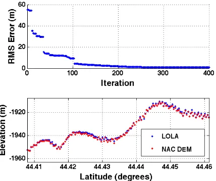
Figure 5. Output of registration program identifying the improvement in the RMS error and a partition of the final registration.
The absolute horizontal and vertical accuracy of the DEM largely depends on the accuracy of the LOLA profiles. Currently, our strategy is to register the DEM to only one profile with the help of the GPS. This procedure ensures that the model is fixed in the down track direction. Other profiles that are coincident with the DEM may not be consistent from profile-to-profile and have errors due to small unknowns in spacecraft position. Areas that are relatively flat are used as elevation controls throughout the remaining portion of the DEM, which more accurately accounts for artificial tilts in the
stereo model. If the remaining LOLA profiles have a spatial and elevation offset from the initial LOLA profile, then the error in the slope of the DEM could be up to 1° in the cross track direction. Errors in the LOLA tracks can propagate over larger distances away from the initial LOLA track. If the cross-track distance is large (3 or more stereo pairs), the DEM can be registered to another LOLA track without interfering with the residual error in the bundle adjustment. Elevation controls are then placed between the co-registered LOLA tracks.
5. APPLICATIONS
The NAC DEMs are the highest resolution topographic resource of the lunar surface, and serve as a valuable tool to both the scientific and space exploration communities. One of the principal uses of the NAC DEMs is to place constraints on the small-scale geomorphological characteristics of key science sites. Constraints can be placed on the composition of surface features by investigating different parameters of the DEM. Studies by Jolliff et al. (2011) used NAC DEMs to characterize locally elevated topographical features in the Compton-Belkovich Th-anomaly. These volcanic domes were not resolvable in other lunar topographical products and helped in understanding the recent geological history of the Moon. Ashley et al. (2011) used NAC topography to identify several areas of negative and positive relief in the Al-Tusi melt deposit associated with the King Crater impact event. DEMs can also be useful for volume estimations. Mahanti et al. (2012) used a DEM mosaic of ponded material in the lunar highland region to calculate the amount of melt that had been emplaced in the floors of craters in the area. Volumes of the ponded material were measured by creating a polynomial mesh of the crater from the DEM and then removing the relatively flat ponded crater floor. Algorithms were then used to recover the DEMs without the filled pond, and this estimate was then employed to calculate the volume of the melt.
Site selection is critical to the success of any future lunar mission. NAC DEMs will be crucial in manned or robotic attempt to land on the surface. Increased hazard avoidance
capabilities in future missions will be able to pick landing sites with a greater emphasis on science return and less on engineering safety criteria (Johnson et al. 2005). NAC DEMs provide a reference for three-dimensional flight plans and provide meaningful hazard avoidance by locating steep slopes, rocks, cliffs, gullies and other landing hazards, which can be avoided by computing the local slope and roughness. A densely populated elevation model will aid on-board landing system that can autonomously and accurately determine spacecraft velocity and position relative to the landing site. DEMs draped with an orthophoto enhance site selection decisions with perspective views and 3-d flight simulations.
Small craters, boulders, and hills can block communication with Earth for landed assists near the poles. Knowledge provided by NAC DEMs of these small obstacles reduce mission risk.
Such DEMs are also needed for traverse planning. Unnecessary movement across the surface wastes precious resources and therefore it is crucial that traverses are optimized in advance to follow a least work path.
6. PRODUCTION AND FUTURE WORK
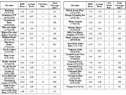
The process of reducing NAC frames to DEMs has evolved to an efficient pipeline procedure with rigorous quality control checks. To date, ASU has processed 130 individual stereo pairs covering 11 CxP sites as well as 53 regions of scientific interest covering a total area of ~20,000 km2 (Table 1). The total products can be downloaded from http://wms.lroc.asu.edu/lroc/ dtm_select. These DEMs are described in the following table.
Site name RMS
Table 1. Regions of interest processed with NAC DEMs and their coverage and accuracies.
7. REFERENCES
Anderson, J.A., Sides, S.C., Soltesz, D.L., Sucharski, T.L., Becker, K. J., 2004. Modernization of the Integrated Software for Imagers and Spectrometers. 35th Lunar and Planetary Science Conference, March 2004, Abs #2039.
Ashley, J.W.; Robinson, M.S.; Ray Hawke, B.; van der Bogert, C.H.; Hiesinger, C.; Sato, H.; Speyerer, E.J.; Enns, A.; Wagner, R.V.; Young, K.; Burns, K.N. 2011. Geology of the King Crater Impact Melt Pond. Journal of Geophysical Research, Planets. In revision.
Cohen, B.A., Nall, M.E., French, R.A., Muery, K.G., Lavoie, A.R., 2008. The Lunar Mapping and Modeling Project (LMMP). 39th Lunar and Planetary Science Conference, Houston, TX, March 2008, Abs #1391.
DeVenecia, K., Walker, A.S., Zhang, B., 2007. New approaches to generating and processing high resolution elevation data with imagery. Photogrammetric Week 2007, edited by D. Fritsch, pp. 297–308, Wichmann, Heidelberg.
Johnson, A., 2005. Vision Guided Landing of an
Autonomous Helicopter in Hazardous Terrain. Robotic and Automation, 2005. IRCA 2005. Proceedings of the 2005 IEEE International Conference on 18-22 April 2005.
Jolliff, B. L., Wiseman, S.A., Lawrence, S.J., Tran, T., Robinson, M.S., Sato, H.S., Hawke, B.R., Scholten. F., Oberst. J., Hiesinger, H., van der Bogert, C.H., Greenhagen, B.T., Glotch, T.D., Paige, D.A, 2011. Non-mare silicic volcanism on the lunar farside at Compton-Belkovich,
Nature Geoscience, 4(8), 566-571.
Mahanti, P., Burns, K., Tran, T., Robinson, M.S., 2012. Measurement of Highland Pond Melt Volumes from LRO NAC DEMs. 43rd Lunar and Planetary Science Conference, Houston, TX, March 2012, Abs #2807.
Mazarico, E., Rowlands, D.D., Neumann, G.A., Smith, D.E., Torrence, M.H., Lemoine, F.G., Zuber, M.T., 2012. Orbit Determination of the Lunar Reconnaissance Orbiter. Journal of Geodesy, 86(3), pp. 193-207.
Moratto, Z.M., Broxton, M.J., Beyer, R.A., Lundy, M., Husman, K., 2010. Ames Stereo Pipeline, NASA’s Open Source Automated Stereogrammetry Software. 41st Lunar and Planetary Science Conference, Houston, TX, March 2010, Abs #1533.
Oberst, J., Scholten, F., Matz, K.-D., Roatsch, T., Wählisch, M., Haase, I., Gläser, I., Gwinner, K., Robinson, M.S., and the LROC Team, 2010. Apollo 17 Landing Site Topography from LROC NAC Stereo Data- First Analysis and Results.
41st Lunar and Planetary Science Conference, Houston, TX, March 2010, Abs #2051.
Robinson, M.S., Brylow, S.M., Tschimmel, M., Humm, D., Lawrence, S.J., Thomas, P.C., Denevi, B.W., Bowman-Cisneros, E., Zerr, J., Ravine, M.A., Caplinger, M.A., Ghaemi, F.T., Schaffner, J.A., Malin, M.C., Mahanti, P., Bartels, A., Anderson, J., Tran, T.N., Eliason, E.M., McEwen, A.S., Turtle, E., Jolliff, B.L., Hiesinger, H., 2010b. Lunar Reconnaissance Orbiter Camera (LROC) Instrument Overview. Space Sci Rev (2010) 150: 81–124 DOI 10.1007/s11214-010-9634-2.
Smith, D.E., Zuber, M.T., Neumann, G.A., Lemoine, F.G., Mazarico, E., Torrence, M.H., McGarry, J.F., Rowlands, D.D., Wead III, J.W., Duxbury, T.H., Aharonson, O., Lucey, P.G., Robinson, M.S., Barmouin, O.S., Cavanaugh, J.F., Sun, X., Liiva, P., Mao, D., Smith, J.C., Bartels, A.E., 2010. Initial Observations from the Lunar Orbiter Laser Altimeter (LOLA). Geophysical Research Letters (2010) 37, LI8204, doi: 10.1029/2010GL043751.
Speyerer, E.J., Burns, K., Robinson, M.S., 2012. Automatic Registration of Altimetric Observations to Stereo Derived Elevation Models. European Lunar Symposium, DLR Berlin, Germany April 2012.
Subramanian, S., Singh A., Sudhakar M. 2003. Evaluation of digital elevation models created from different satellite images. In. Proceedings of Map India 2003. pp. 28–31 January, New Delhi.)
Tran, T., Rosiek, M.R., Beyer, R., Mattson, S., Howington-Kraus, A., Robinson, M.S., Archinal, B.A., Edmundson, K. Harbour, D., Anderson, E., and the LROC Science Team, 2010. Generating Digital Terrain Models Using LROC NAC Images, paper presented at International Symposium IV/7 Planetary Mapping and Databases, Institute of Planetary Research, Orland, FL.
Warmerdam, F. 2008. The Geospatial Data Abstraction Library. Open Source Approaches in Spatial Data Handling, Advances in Geographic Information Science, Vol. 2, pp. 87-104.
Zuber, M.T., Smith, D.E., Zellar, R.S., Neumann, G.A., Sun, X., Katz, R.B., Kleyner, I., Matuszeski, A., McGarry, J.F., Ott, M.N., Ramos-Izquierdo, L. Rowlands, D., Torrence, M.H., Zagwodzki, T.W., 2010. The Lunar Reconnaissance Orbiter Laser Ranging Investigation. Space Sci Rev (2010) 150: 63–80 DOI 10.1007/s11214-009-9511-z.