Aircraft Metal Structural Repair
The satisfactory performance of an aircraft requires continuous maintenance of aircraft structural integrity. It is important that metal structural repairs be made according to the best available techniques because improper repair techniques can pose an immediate or potential danger. The reliability of an aircraft depends on the quality of the design, as well as the workmanship used in making the repairs. The design of an aircraft metal structural repair is complicated by the requirement that an aircraft be as light as possible. If weight were not a critical factor, repairs could be made with a large margin of safety. In actual practice, repairs must be strong enough to carry all of the loads with the required factor of safety, but they must not have too much extra strength. For example, a joint that is too weak cannot be tolerated, but a joint that is too strong can create stress risers that may cause cracks in other locations.
As discussed in Chapter 3, Aircraft Fabric Covering, sheet metal aircraft construction dominates modern aviation. Generally, sheet metal made of aluminum alloys is used in airframe sections that serve as both the structure and outer aircraft covering, with the metal parts joined with rivets or other types of fasteners. Sheet metal is used extensively in many types of aircraft from airliners to single engine airplanes, but it may also appear as part of a composite airplane, such as in an instrument panel. Sheet metal is obtained by rolling metal into lat sheets of various thicknesses ranging from thin (leaf) to plate (pieces thicker than 6 mm or 0.25 inch). The thickness of sheet metal, called gauge, ranges from 8 to 30 with the higher gauge denoting thinner metal. Sheet metal can be cut and bent into a variety of shapes.
Damage to metal aircraft structures is often caused by corrosion, erosion, normal stress, and accidents and mishaps. Sometimes aircraft structure modiications require extensive structural rework. For example, the installation of winglets on aircraft not only replaces a wing tip with a winglet, but also requires extensive reinforcing of the wing structure to carry additional stresses.
Numerous and varied methods of repairing metal structural portions of an aircraft exist, but no set of speciic repair patterns applies in all cases. The problem of repairing a damaged section is usually solved by duplicating the original part in strength, kind of material, and dimensions. To make a structural repair, the aircraft technician needs a good working knowledge of sheet metal forming methods and techniques. In general, forming means changing the shape by bending and forming solid metal. In the case of aluminum, this is usually done at room temperature. All repair parts are shaped to it in place before they are attached to the aircraft or component. Forming may be a very simple operation, such as making a single bend or a single curve, or it may be a complex operation, requiring a compound curvature. Before forming a part, the aircraft technician must give some thought to the complexity of the bends, the material type, the material thickness, the material temper, and the size of the part being fabricated. In most cases, these factors determine which forming method to use. Types of forming discussed in this chapter include bending, brake forming, stretch forming, roll forming, and spinning. The aircraft technician also needs a working knowledge of the proper use of the tools and equipment used in forming metal.
In addition to forming techniques, this chapter introduces the airframe technician to the tools used in sheet metal construction and repair, structural fasteners and their installation, how to inspect, classify, and assess metal structural damage, common repair practices, and types of repairs.
The repairs discussed in this chapter are typical of those used in aircraft maintenance and are included to introduce some of the operations involved. For exact information about speciic repairs, consult the manufacturer’s maintenance or structural repair manuals (SRM). General repair instructions are also discussed in Advisory Circular (AC) 43.13.1, Acceptable Methods, Techniques, and Practices—Aircraft Inspection and Repair.
Stresses in Structural Members
An aircraft structure must be designed so that it accepts all of the stresses imposed upon it by the light and ground loads without any permanent deformation. Any repair made must
accept the stresses, carry them across the repair, and then transfer them back into the original structure. These stresses are considered as lowing through the structure, so there must be a continuous path for them, with no abrupt changes in cross-sectional areas along the way. Abrupt changes in cross-sectional areas of aircraft structure that are subject to cycle loading or stresses result in a stress concentration that may induce fatigue cracking and eventual failure. A scratch or gouge in the surface of a highly stressed piece of metal causes a stress concentration at the point of damage and could lead to failure of the part. Forces acting on an aircraft, whether it is on the ground or in light, introduce pulling, pushing, or twisting forces within the various members of the aircraft structure. While the aircraft is on the ground, the weight of the wings, fuselage, engines, and empennage causes forces to act downward on the wing and stabilizer tips, along the spars and stringers, and on the bulkheads and formers. These forces are passed from member to member causing bending, twisting, pulling, compression, and shearing forces. As the aircraft takes off, most of the forces in the fuselage continue to act in the same direction; because of the motion of the aircraft, they increase in intensity. The forces on the wingtips and the wing surfaces, however, reverse direction; instead of being downward forces of weight, they become upward forces of lift. The forces of lift are exerted irst against the skin and stringers, then are passed on to the ribs, and inally are transmitted through the spars to be distributed through the fuselage. The wings bend upward at their ends and may lutter slightly during light. This wing bending cannot be ignored by the manufacturer in the original design and construction and cannot be ignored during maintenance. It is surprising how an aircraft structure composed of structural members and skin rigidly riveted or bolted together, such as a wing, can bend or act so much like a leaf spring. The six types of stress in an aircraft are described as tension, compression, shear, bearing, bending, and torsion (or twisting). The irst four are commonly called basic stresses; the last two, combination stresses. Stresses usually act in combinations rather than singly. [Figure 4-1]
Tension
Tension is the stress that resists a force that tends to pull apart. The engine pulls the aircraft forward, but air resistance tries to hold it back. The result is tension, which tends to stretch the aircraft. The tensile strength of a material is measured in pounds per square inch (psi) and is calculated by dividing the load (in pounds) required to pull the material apart by its cross-sectional area (in square inches).
Figure 4-1. Stresses in aircraft structures. Compression
Tension
E. Bending A. Tension
B. Compression
C. Torsion
D. Shear
Figure 4-2. Bearing stress. Rivets Top sheet is bearing against the bottom sheet. Fasteners are pressing top sheet against bottom bearing
The force that tries to pull the two sheets apart
Bearing stress
involving tension must take into consideration the net area of the member. Net area is deined as the gross area minus that removed by drilling holes or by making other changes in the section. Placing rivets or bolts in holes makes no appreciable difference in added strength, as the rivets or bolts will not transfer tensional loads across holes in which they are inserted.
Compression
Compression, the stress that resists a crushing force, tends to shorten or squeeze aircraft parts. The compressive strength of a material is also measured in psi. Under a compressive load, an undrilled member is stronger than an identical member with holes drilled through it. However, if a plug of equivalent or stronger material is itted tightly in a drilled member, it transfers compressive loads across the hole, and the member carries approximately as large a load as if the hole were not there. Thus, for compressive loads, the gross or total area may be used in determining the stress in a member if all holes are tightly plugged with equivalent or stronger material.
Shear
Shear is the stress that resists the force tending to cause one layer of a material to slide over an adjacent layer. Two riveted plates in tension subject the rivets to a shearing force. Usually, the shear strength of a material is either equal to or less than its tensile or compressive strength. Shear stress concerns the aviation technician chiely from the standpoint of the rivet and bolt applications, particularly when attaching sheet metal, because if a rivet used in a shear application gives way, the riveted or bolted parts are pushed sideways.
Bearing
Bearing stress resists the force that the rivet or bolt places on the hole. As a rule, the strength of the fastener should be such that its total shear strength is approximately equal to the total bearing strength of the sheet material. [Figure 4-2]
Torsion
Figure 4-3. Scales.
reference axis at right angles to these planes. This action may be illustrated by a rod ixed solidly at one end and twisted by a weight placed on a lever arm at the other, producing the equivalent of two equal and opposite forces acting on the rod at some distance from each other. A shearing action is set up all along the rod, with the center line of the rod representing the neutral axis.
Bending
Bending (or beam stress) is a combination of compression and tension. The rod in Figure 4-1E has been shortened (compressed) on the inside of the bend and stretched on the outside of the bend. Note that the bending stress causes a tensile stress to act on the upper half of the beam and a compressive stress on the lower half. These stresses act in opposition on the two sides of the center line of the member, which is called the neutral axis. Since these forces acting in opposite directions are next to each other at the neutral axis, the greatest shear stress occurs along this line, and none exists at the extreme upper or lower surfaces of the beam.
Tools for Sheet Metal Construction and
Repair
Without modern metalworking tools and machines, the job of the airframe technician would be more dificult and tiresome, and the time required to inish a task would be much greater. These specialized tools and machines help the airframe technician construct or repair sheet metal in a faster, simpler, and better manner than possible in the past. Powered by human muscle, electricity, or compressed air, these tools are used to lay out, mark, cut, sand, or drill sheet metal. Layout Tools
Before itting repair parts into an aircraft structure, the new sections must be measured and marked, or laid out to the dimensions needed to make the repair part. Tools utilized for this process are discussed in this section.
Scales
Scales are available in various lengths, with the 6-inch and 12-inch scales being the most common and affordable. A scale with fractions on one side and decimals on the other side is very useful. To obtain an accurate measurement, measure with the scale held on edge from the 1-inch mark instead of the end. Use the graduation marks on the side to set a divider or compass. [Figure 4-3]
Combination Square
A combination square consists of a steel scale with three heads that can be moved to any position on the scale and locked in place. The three heads are a stock head that measures 90° and 45° angles, a protractor head that can
measure any angle between the head and the blade, and a center head that uses one side of the blade as the bisector of a 90° angle. The center of a shaft can be found by using the center head. Place the end of the shaft in the V of the head and scribe a line along the edge of the scale. Rotate the head about 90° and scribe another line along the edge of the scale. The two lines will cross at the center of the shaft. [Figure 4-4] Dividers
Dividers are used to transfer a measurement from a device to a scale to determine its value. Place the sharp points at the locations from which the measurement is to be taken. Then, place the points on a steel machinist’s scale, but put one of the points on the 1-inch mark and measure from there.
[Figure 4-5]
Rivet Spacers
Figure 4-4. Combination square.
11 2
0
180
90
3 4 5 8 9 10
Scriber
Level
Stock head Protractor head Center head
Figure 4-5. Divider.
Figure 4-6. Rivet spacer.
Figure 4-7. Scribe.
aluminum. Make the layout on the protective membrane if it is still on the material, or mark directly on the material with a iber-tipped pen, such as a ine-point Sharpie®, or cover
the material with masking tape and then mark on the tape.
Scribes
A scribe is a pointed instrument used to mark or score metal to show where it is to be cut. A scribe should only be used when marks will be removed by drilling or cutting because it makes scratches that weaken the material and could cause corrosion. [Figure 4-7]
Punches
Figure 4-8. Prick punch.
Figure 4-9. Center punch.
Figure 4-10. Automatic center punch.
Figure 4-11. Transfer punch. Transfer punch
Use old skin as template
New skin Prick Punch
A prick punch is primarily used during layout to place reference marks on metal because it produces a small indentation. [Figure 4-8] After layout is finished, the indentation is enlarged with a center punch to allow for drilling. The prick punch can also be used to transfer dimensions from a paper pattern directly onto the metal. Take the following precautions when using a prick punch:
• Never strike a prick punch a heavy blow with a hammer because it could bend the punch or cause excessive damage to the item being worked.
• Do not use a prick punch to remove objects from holes because the point of the punch spreads the object and causes it to bind even more.
Center Punch
A center punch is used to make indentations in metal as an aid in drilling. [Figure 4-9] These indentations help the drill, which has a tendency to wander on a lat surface, stay on the mark as it goes through the metal. The traditional center punch is used with a hammer, has a heavier body than the prick punch, and has a point ground to an angle of about 60°. Take the following precautions when using a center punch:
• Never strike the center punch with enough force to dimple the item around the indentation or cause the metal to protrude through the other side of the sheet. • Do not use a center punch to remove objects from holes
because the point of the punch spreads the object and causes it to bind even more.
Automatic Center Punch
The automatic center punch performs the same function as an ordinary center punch, but uses a spring tension mechanism to create a force hard enough to make an indentation without the need for a hammer. The mechanism automatically strikes a blow of the required force when placed where needed and pressed. This punch has an adjustable cap for regulating the stroke; the point can be removed for replacement or sharpening. Never strike an automatic center punch with a hammer. [Figure 4-10]
Transfer Punch
A transfer punch uses a template or existing holes in the structure to mark the locations of new holes. The punch is centered in the old hole over the new sheet and lightly tapped with a mallet. The result should be a mark that serves to locate the hole in the new sheet. [Figure 4-11]
Drive Punch
Figure 4-13. Pin punch.
Figure 4-12. Drive punch.
Figure 4-14. Chassis punch.
Figure 4-15. Awl.
Figure 4-16. Awl usage. 4
5 6 1
2 3
7 8
9 10
11 12 Pin Punch
The pin punch typically has a straight shank characterized by a hexagonal body. Pin punch points are sized in 1⁄32-inch
increments of an inch and range from 1⁄16-inch to 3⁄8-inch in
diameter. The usual method for driving out a pin or bolt is to start working it out with a drive punch until the shank of the punch is touching the sides of the hole. Then use a pin punch to drive the pin or bolt the rest of the way out of the hole. [Figure 4-13]
Chassis Punch
A chassis punch is used to make holes in sheet metal parts for the installation of instruments and other avionics appliance, as well as lightening holes in ribs and spars. Sized in 1⁄16 of
an inch, they are available in sizes from 1⁄2 inch to 3 inches. [Figure 4-14]
Awl
A pointed tool for marking surfaces or for punching small holes, an awl is used in aircraft maintenance to place scribe marks on metal and plastic surfaces and to align holes, such as in the installation of a deicer boot. [Figure 4-15]
Procedures for one use of an awl:
1. Place the metal to be scribed on a lat surface. Place a ruler or straightedge on the guide marks already measured and placed on the metal.
2. Remove the protective cover from the awl.
Figure 4-17. Hole duplicator.
New skin
Old skin Angle
Figure 4-18. Kett saw.
Figure 4-19. Pneumatic circular saw.
Hole Duplicator
Available in a variety of sizes and styles, hole duplicators, or hole inders, utilize the old covering as a template to locate and match existing holes in the structure. Holes in a replacement sheet or in a patch must be drilled to match existing holes in the structure and the hole duplicator simpliies this process. Figure 4-17 illustrates one type of hole duplicator. The peg on the bottom leg of the duplicator its into the existing rivet hole. To make the hole in the replacement sheet or patch, drill through the bushing on the top leg. If the duplicator is properly made, holes drilled in this manner are in perfect alignment. A separate duplicator must be used for each diameter of rivet.
Cutting Tools
Powered and nonpowered metal cutting tools available to the aviation technician include various types of saws, nibblers, shears, sanders, notchers, and grinders.
Circular-Cutting Saws
The circular cutting saw cuts with a toothed, steel disk that rotates at high speed. Handheld or table mounted and powered by compressed air, this power saw cuts metal or wood. To prevent the saw from grabbing the metal, keep a irm grip on the saw handle at all times. Check the blade carefully for cracks prior to installation because a cracked blade can ly apart during use, possibly causing serious injury.
Kett Saw
The Kett saw is an electrically operated, portable circular cutting saw that uses blades of various diameters. [Figure 4-18]
Since the head of this saw can be turned to any desired angle, it is useful for removing damaged sections on a stringer. The advantages of a Kett saw include:
1. Can cut metal up to 3⁄16-inch in thickness.
2. No starting hole is required.
3. A cut can be started anywhere on a sheet of metal. 4. Can cut an inside or outside radius.
Pneumatic Circular Cutting Saw
Figure 4-20. Reciprocating saw.
Figure 4-21. Die grinder and cut-off wheel.
Figure 4-22. Nibbler.
Figure 4-23. Power squaring shear. Nibblers
Usually powered by compressed air, the nibbler is another tool for cutting sheet metal. Portable nibblers utilize a high speed blanking action (the lower die moves up and down and meets the upper stationary die) to cut the metal. [Figure 4-22]
The shape of the lower die cuts out small pieces of metal approximately 1⁄16 inch wide.
The cutting speed of the nibbler is controlled by the thickness of the metal being cut. Nibblers satisfactorily cut through sheets of metal with a maximum thickness of 1⁄16 inch. Too
much force applied to the metal during the cutting operation clogs the dies (shaped metal), causing them to fail or the motor to overheat. Both electric and hand nibblers are available. Shop Tools
Due to size, weight, and/or power source, shop tools are usually in a ixed location, and the airframe part to be constructed or repaired is brought to the tool.
Squaring Shear
The squaring shear provides the airframe technician with a convenient means of cutting and squaring sheet metal. Available as a manual, hydraulic, or pneumatic model, this shear consists of a stationary lower blade attached to a bed and a movable upper blade attached to a crosshead.
[Figure 4-23] Reciprocating Saw
The versatile reciprocating saw achieves cutting action through a push and pull (reciprocating) motion of the blade. This saw can be used right sideup or upside down, a feature that makes it handier than the circular saw for working in tight or awkward spots. A variety of blade types are available for reciprocating saws; blades with iner teeth are used for cutting through metal. The portable, air-powered reciprocating saw uses a standard hacksaw blade and can cut a 360° circle or a square or rectangular hole. Unsuited for ine precision work, this saw is more dificult to control than the pneumatic circular cutting saw. A reciprocating saw should be used in such a way that at least two teeth of the saw blade are cutting at all times. Avoid applying too much downward pressure on the saw handle because the blade may break. [Figure 4-20]
Cut-off Wheel
Figure 4-24. Foot-operated squaring shear.
Figure 4-25. Throatless shears.
A hand lever operates the cutting blade which is the top blade. Throatless shears made by the Beverly Shear Manufacturing Corporation, called BeverlyTM shears, are often used. Scroll Shears
Scroll shears are used for cutting irregular lines on the inside of a sheet without cutting through to the edge.
[Figure 4-26] The upper cutting blade is stationary while the lower blade is movable. A handle connected to the lower blade operates the machine.
Rotary Punch Press
Used in the airframe repair shop to punch holes in metal parts, the rotary punch can cut radii in corners, make washers, and perform many other jobs where holes are required.
[Figure 4-27] The machine is composed of two cylindrical turrets, one mounted over the other and supported by the frame, with both turrets synchronized to rotate together. Index pins, which ensure correct alignment at all times, may be released from their locking position by rotating a lever on the right side of the machine. This action withdraws the index pins from the tapered holes and allows an operator to turn the turrets to any size punch desired.
Two squaring fences, consisting of thick strips of metal used for squaring metal sheets, are placed on the bed. One squaring fence is placed on the right side and one on the left to form a 90° angle with the blades. A scale graduated in fractions of an inch is scribed on the bed for ease in placement.
To make a cut with a foot shear, move the upper blade down by placing the foot on the treadle and pushing downward. Once the metal is cut and foot pressure removed, a spring raises the blade and treadle. Hydraulic or pneumatic models utilize remote foot pedals to ensure operator safety. The squaring shear performs three distinctly different operations:
1. Cutting to a line 2. Squaring
3. Multiple cutting to a speciic size
When cutting to a line, place the sheet on the bed of the shears in front of the cutting blade with the cutting line even with the cutting edge of the bed. To cut the sheet with a foot shear, step on the treadle while holding the sheet securely in place. Squaring requires several steps. First, one end of the sheet is squared with an edge (the squaring fence is usually used on the edge). Then, the remaining edges are squared by holding one squared end of the sheet against the squaring fence and making the cut, one edge at a time, until all edges have been squared.
When several pieces must be cut to the same dimensions, use the backstop, located on the back of the cutting edge on most squaring shears. The supporting rods are graduated in fractions of an inch and the gauge bar may be set at any point on the rods. Set the gauge bar the desired distance from the cutting blade of the shears and push each piece to be cut against the gauge bar. All the pieces can then be cut to the same dimensions without measuring and marking each one separately. Foot-operated shears have a maximum metal cutting capacity of 0.063 inch of aluminum alloy. Use powered squaring shears for cutting thicker metals. [Figure 4-24]
Throatless Shear
Figure 4-26. Scroll shears.
Figure 4-27. Rotary punch press.
Figure 4-29. Combination disk and belt sander.
Figure 4-28. Band saw.
When rotating the turret to change punches, release the index lever when the desired die is within 1 inch of the ram, and continue to rotate the turret slowly until the top of the punch holder slides into the grooved end of the ram. The tapered index locking pins will then seat themselves in the holes provided and, at the same time, release the mechanical locking device, which prevents punching until the turrets are aligned.
To operate the machine, place the metal to be worked between the die and punch. Pull the lever on the top of the machine toward the operator, actuating the pinion shaft, gear segment, toggle link, and the ram, forcing the punch through the metal. When the lever is returned to its original position, the metal is removed from the punch.
The diameter of the punch is stamped on the front of each die holder. Each punch has a point in its center that is placed in the center punch mark to punch the hole in the correct location.
Band Saw
A band saw consists of a toothed metal band coupled to, and continuously driven around, the circumferences of two wheels. It is used to cut aluminum, steel, and composite parts.
[Figure 4-28] The speed of the band saw and the type and style of the blade depends on the material to be cut. Band saws are often designated to cut one type of material, and if a different material is to be cut, the blade is changed. The speed is controllable and the cutting platform can be tilted to cut angled pieces.
Disk Sander
Disk sanders have a powered abrasive-covered disk or belt and are used for smoothing or polishing surfaces. The sander unit uses abrasive paper of different grits to trim metal parts. It is much quicker to use a disk sander than to ile a part to the correct dimension. The combination disk and belt sander has a vertical belt sander coupled with a disk sander and is often used in a metal shop. [Figure 4-29]
Belt Sander
Figure 4-31. Notcher.
Figure 4-32. Power notcher.
Figure 4-33. Grinder.
Tool rest
Figure 4-30. Belt sander.
available as a vertical or horizontal unit. The tension and tracking of the abrasive belt can be adjusted so the belt runs in the middle. [Figure 4-30]
Notcher
The notcher is used to cut out metal parts, with some machines capable of shearing, squaring, and trimming metal. [Figure 4-31] The notcher consists of a top and bottom die and most often cuts at a 90° angle, although some machines can cut metal into angles up to 180°. Notchers are available in manual and pneumatic models able to cut various thicknesses of mild steel and aluminum. This is an excellent tool for quickly removing corners from sheet metal parts. [Figure 4-32]
Wet or Dry Grinder
Grinding machines come in a variety of types and sizes, depending upon the class of work for which they are to be used. Dry and/or wet grinders are found in airframe repair
shops. Grinders can be bench or pedestal mounted. A dry grinder usually has a grinding wheel on each end of a shaft that runs through an electric motor or a pulley operated by a belt. The wet grinder has a pump to supply a low of water on a single grinding wheel. The water acts as a lubricant for faster grinding while it continuously cools the edge of the metal, reducing the heat produced by material being ground against the wheel. It also washes away any bits of metal or abrasive removed during the grinding operation. The water returns to a tank and can be re-used.
Grinders are used to sharpen knives, tools, and blades as well as grinding steel, metal objects, drill bits, and tools.
Figure 4-34. Straight snips.
Figure 4-35. Aviation snips.
The bench grinder is generally equipped with one medium-grit and one ine-medium-grit abrasive wheel. The medium-medium-grit wheel is usually used for rough grinding where a considerable quantity of material is to be removed or where a smooth inish is unimportant. The ine-grit wheel is used for sharpening tools and grinding to close limits. It removes metal more slowly, gives the work a smooth inish, and does not generate enough heat to anneal the edges of cutting tools.
Before using any type of grinder, ensure that the abrasive wheels are irmly held on the spindles by the lange nuts. An abrasive wheel that comes off or becomes loose could seriously injure the operator in addition to ruining the grinder. A loose tool rest could cause the tool or piece of work to be “grabbed” by the abrasive wheel and cause the operator’s hand to come in contact with the wheel, possibly resulting in severe wounds.
Always wear goggles when using a grinder, even if eyeshields are attached to the grinder. Goggles should it irmly against the face and nose. This is the only way to protect the eyes from the ine pieces of steel. Goggles that do not it properly should be exchanged for ones that do it. Be sure to check the abrasive wheel for cracks before using the grinder. A cracked abrasive wheel is likely to ly apart when turning at high speeds. Never use a grinder unless it is equipped with wheel guards that are irmly in place.
Grinding Wheels
A grinding wheel is made of a bonded abrasive and provides an eficient way to cut, shape, and inish metals. Available in a wide variety of sizes and numerous shapes, grinding wheels are also used to sharpen knives, drill bits, and many other tools, or to clean and prepare surfaces for painting or plating. Grinding wheels are removable and a polishing or bufing wheel can be substituted for the abrasive wheel. Silicon carbide and aluminum oxide are the kinds of abrasives used in most grinding wheels. Silicon carbide is the cutting agent for grinding hard, brittle material, such as cast iron. It is also used in grinding aluminum, brass, bronze, and copper. Aluminum oxide is the cutting agent for grinding steel and other metals of high tensile strength.
Hand Cutting Tools
Many types of hand cutting tools are available to cut light gauge sheet metal. Four cutting tools commonly found in the air frame repair shop are straight hand snips, aviation snips, iles, and burring tools.
Straight Snips
Straight snips, or sheet metal shears, have straight blades with cutting edges sharpened to an 85° angle.
[Figure 4-34] Available in sizes ranging from 6 to 14 inches, they cut aluminum up to 1⁄16 of an inch. Straight snips can be
used for straight cutting and large curves, but aviation snips are better for cutting circles or arcs.
Aviation Snips
Aviation snips are used to cut holes, curved parts, round patches, and doublers (a piece of metal placed under a part to make it stiffer) in sheet metal. Aviation snips have colored handles to identify the direction of the cuts: yellow aviation snips cut straight, green aviation snips curve right, and red aviation snips curve left. [Figure 4-35]
Files
Figure 4-37. Die grinder.
Figure 4-38. Burring tools.
Figure 4-36. Files.
The portion of the ile on which the teeth are cut is called the face. The tapered end that its into the handle is called the tang. The part of the ile where the tang begins is the heel. The length of a ile is the distance from the point or tip to the heel and does not include the tang. The teeth of the ile do the cutting. These teeth are set at an angle across the face of the ile. A ile with a single row of parallel teeth is called a single-cut ile. The teeth are cut at an angle of 65°–85° to the centerline, depending on the intended use of the ile. Files that have one row of teeth crossing another row in a crisscross pattern are called double-cut iles. The angle of the irst set usually is 40°–50° and that of the crossing teeth 70°–80°. Crisscrossing produces a surface that has a very large number of little teeth that slant toward the tip of the ile. Each little tooth looks like an end of a diamond point cold chisel.
Files are graded according to the tooth spacing; a coarse ile has a small number of large teeth, and a smooth ile has a large number of ine teeth. The coarser the teeth, the more metal is removed on each stroke of the ile. The terms used to indicate the coarseness or ineness of a ile are rough, coarse, bastard, second cut, smooth, and dead smooth, and the ile may be either single cut or double cut. Files are further classiied according to their shape. Some of the more common types are: lat, triangle, square, half round, and round.
There are several iling techniques. The most common is to remove rough edges and slivers from the inished part before it is installed. Crossiling is a method used for iling the edges of metal parts that must it tightly together. Crossiling involves clamping the metal between two strips of wood and iling the edge of the metal down to a preset line. Draw iling is used when larger surfaces need to be smoothed and squared. It is done by drawing the ile over the entire surface of the work.
To protect the teeth of a ile, iles should be stored separately in a plastic wrap or hung by their handles. Files kept in a toolbox should be wrapped in waxed paper to prevent rust from forming on the teeth. File teeth can be cleaned with a ile card.
Die Grinder
A die grinder is a handheld tool that turns a mounted cutoff wheel, rotary ile, or sanding disk at high speed.
[Figure 4-37] Usually powered by compressed air, electric die grinders are also used. Pneumatic die grinders run at 12,000 to 20,000 revolutions per minute (rpm) with the rotational speed controlled by the operator who uses a hand- or foot-operated throttle to vary the volume of compressed air. Available in straight, 45°, and 90° models, the die grinder is excellent for weld breaking, smoothing sharp edges, deburring, porting, and general high-speed polishing, grinding, and cutting.
Burring Tool
This type of tool is used to remove a burr from an edge of a sheet or to deburr a hole. [Figure 4-38]
Hole Drilling
Figure 4-39. Drill motors.
Figure 4-41. Nutplate drill.
Figure 4-40. Angle drill motors.
Portable Power Drills
Portable power drills operate by electricity or compressed air. Pneumatic drill motors are recommended for use on repairs around lammable materials where potential sparks from an electric drill motor might become a ire hazard.
When using the portable power drill, hold it irmly with both hands. Before drilling, be sure to place a backup block of wood under the hole to be drilled to add support to the metal structure. The drill bit should be inserted in the chuck and tested for trueness or vibration. This may be visibly checked by running the motor freely. A drill bit that wobbles or is slightly bent should not be used since such a condition causes enlarged holes. The drill should always be held at right angles to the work regardless of the position or curvatures. Tilting the drill at any time when drilling into or withdrawing from the material may cause elongation (egg shape) of the hole. When drilling through sheet metal, small burrs are formed around the edge of the hole. Burrs must be removed to allow rivets or bolts to it snugly and to prevent scratching. Burrs may be removed with a bearing scraper, a countersink, or a drill bit larger than the hole. If a drill bit or countersink is used, it should be rotated by hand. Always wear safety goggles while drilling.
Pneumatic Drill Motors
Pneumatic drill motors are the most common type of drill motor for aircraft repair work. [Figure 4-39] They are light weight and have suficient power and good speed control. Drill motors are available in many different sizes and models. Most drill motors used for aircraft sheet metal work are rated at 3,000 rpm, but if drilling deep holes or drilling in hard materials, such as corrosion resistant steel or titanium, a drill motor with more torque and lower rpm should be selected to prevent damage to tools and materials.
Right Angle and 45° Drill Motors
Right angle and 45° drill motors are used for positions that are not accessible with a pistol grip drill motor. Most right angle drill motors use threaded drill bits that are available in several lengths. Heavy-duty right angle drills are equipped with a chuck similar to the pistol grip drill motor. [Figure 4-40]
Two Hole
Special drill motors that drill two holes at the same time are used for the installation of nutplates. By drilling two holes at the same time, the distance between the holes is ixed and the holes line up perfectly with the holes in the nutplate.
[Figure 4-41]
Drill Press
Figure 4-42. Drill press.
When using a drill press, the height of the drill press table is adjusted to accommodate the height of the part to be drilled. When the height of the part is greater than the distance between the drill and the table, the table is lowered. When the height of the part is less than the distance between the drill and the table, the table is raised.
After the table is properly adjusted, the part is placed on the table and the drill is brought down to aid in positioning the metal so that the hole to be drilled is directly beneath the point of the drill. The part is then clamped to the drill press table to prevent it from slipping during the drilling operation. Parts not properly clamped may bind on the drill and start spinning, causing serious cuts on the operator’s arms or body, or loss of ingers or hands. Always make sure the part to be drilled is properly clamped to the drill press table before starting the drilling operation.
The degree of accuracy that it is possible to attain when using the drill press depends to a certain extent on the condition of the spindle hole, sleeves, and drill shank. Therefore, special care must be exercised to keep these parts clean and free from nicks, dents, and warpage. Always be sure that the sleeve is securely pressed into the spindle hole. Never insert a broken drill in a sleeve or spindle hole. Be careful never to use the sleeve-clamping vise to remove a drill since this may cause the sleeve to warp.
The drill speed on a drill press is adjustable. Always select the optimum drill speed for the material to be drilled. Technically, the speed of a drill bit means its speed at the circumference, in surface feet per minute (sfm). The recommended speed for drilling aluminum alloy is from 200 to 300 sfm, and for mild steel is 30 to 50 sfm. In practice, this must be converted into rpm for each size drill. Machinist and mechanic handbooks include drill rpm charts or drill rpm may be computed by use of the formula:
CS × 4 = rpm D
CS = The recommended cutting speed in sfm D = The diameter of the drill bit in inches
Example: At what rpm should a 1⁄8-inch drill turn to drill
aluminum at 300 sfm?
Drill Extensions and Adapters
When access to a place where drilling is difficult or impossible with a straight drill motor, various types of drill extensions and adapters are used.
Extension Drill Bits
Extension drill bits are widely used for drilling holes in locations that require reaching through small openings or past projections. These drill bits, which come in 6- to 12-inch lengths, are high speed with spring-tempered shanks. Extension drill bits are ground to a special notched point, which reduces end thrust to a minimum. When using extension drill bits always:
1. Select the shortest drill bit that will do the job. It is easier to control.
2. Check the drill bit for straightness. A bent drill bit makes an oversized hole and may whip, making it dificult to control.
3. Keep the drill bit under control. Extension drills smaller than 1⁄4-inch must be supported by a drill
guard made from a piece of tubing or spring to prevent whipping.
Straight Extension
A straight extension for a drill can be made from an ordinary piece of drill rod. The drill bit is attached to the drill rod by shrink itting, brazing, or silver soldering.
Angle Adapters
Angle adapters can be attached to an electric or pneumatic drill when the location of the hole is inaccessible to a straight drill. Angle adapters have an extended shank fastened to the chuck of the drill. The drill is held in one hand and the adapter in the other to prevent the adapter from spinning around the drill chuck.
Snake Attachment
Figure 4-43. Snake attachment.
Figure 4-44. Parts of a drill.
Figure 4-45. Types of drill bits.
Notched point chisel edge Flute Cutting lips Land
Body Shank
HSS
HSS HSS HSS HSS HSS HSS HSS HSS
HSS
HSS HSS
HSS
HSS HSS HSS HSS HSS HSS HSS
HSS
HSS
v
v v v v / / / / / / / /
High speed steel, short shank
High speed steel, standard length (jobbers length)
Step drill
Cobalt vanadium alloy, standard length
Figure 4-46. Twist drill bits.
Types of Drill Bits
A wide variety of drill bits including specialty bits for speciic jobs are available. Figure 4-44 illustrates the parts of the drill bit and Figure 4-45 shows some commonly used drill bits. High speed steel (HSS) drill bits come in short shank or standard length, sometimes called jobbers length. HSS drill bits can withstand temperatures nearing the critical range of 1,400 °F (dark cherry red) without losing their hardness. The industry standard for drilling metal (aluminum, steel, etc.), these drill bits stay sharper longer.
Step Drill Bits
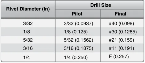
Typically, the procedure for drilling holes larger than 3⁄16
inch in sheet metal is to drill a pilot hole with a No. 40 or No. 30 drill bit and then to oversize with a larger drill bit to the correct size. The step drill combines these two functions into one step. The step drill bit consists of a smaller pilot drill point that drills the initial small hole. When the drill bit is advanced further into the material, the second step of the drill bit enlarges the hole to the desired size.
Step drill bits are designed to drill round holes in most metals, plastic, and wood. Commonly used in general construction and plumbing, they work best on softer materials, such as plywood, but can be used on very thin sheet metal. Step drill bits can also be used to deburr holes left by other bits.
Cobalt Alloy Drill Bits
Cobalt alloy drill bits are designed for hard, tough metals like corrosion-resistant steel and titanium. It is important for the aircraft technician to note the difference between HSS and cobalt, because HSS drill bits wear out quickly when drilling titanium or stainless. Cobalt drill bits are excellent for drilling titanium or stainless steel, but do not produce a quality hole in aluminum alloys. Cobalt drill bits can be recognized by thicker webs and a taper at the end of the drill shank.
Twist Drill Bits
Easily the most popular drill bit type, the twist drill bit has spiral grooves or lutes running along its working length.
80
Figure 4-47. Drill sizes and decimal equivalents.
The standard twist drill bits used for drilling aluminum are made from HSS and have a 135° split point. Drill bits for titanium are made from cobalt vanadium for increased wear resistance.
Drill Bit Sizes
Drill diameters are grouped by three size standards: number, letter, and fractional. The decimal equivalents of standard drill are shown in Figure 4-47.
Drill Lubrication
Normal drilling of sheet material does not require lubrication, but lubrication should be provided for all deeper drilling.
Figure 4-48. Reamers.
1
2
3
Figure 4-49. Drill stop. HSS
HSS HSS HSS HSS HSS HSS HSSSS
Figure 4-50. Drill bushings.
Arm-type bushing holder Bushing holder
Figure 4-51. Bushing holder.
deep drilling, the drill should be withdrawn at intervals to relieve chip packing and to ensure the lubricant reaches the point. As a general rule, if the drill is large or the material hard, use a lubricant.
Reamers
Reamers, used for enlarging holes and inishing them smooth to a required size, are made in many styles. They can be straight or tapered, solid or expansive, and come with straight or helical lutes. Figure 4-48 illustrates three types of reamers:
1. Three or four luted production bullet reamers are customarily used where a iner inish and/or size is needed than can be achieved with a standard drill bit. 2. Standard or straight reamer.
3. Piloted reamer, with the end reduced to provide accurate alignment.
The cylindrical parts of most straight reamers are not cutting edges, but merely grooves cut for the full length of the reamer body. These grooves provide a way for chips to escape and a channel for lubricant to reach the cutting edge. Actual cutting is done on the end of the reamer. The cutting edges are normally ground to a bevel of 45° ± 5°.
Reamer lutes are not designed to remove chips like a drill. Do not attempt to withdraw a reamer by turning it in the reverse direction because chips can be forced into the surface, scarring the hole.
Drill Stops
A spring drill stop is a wise investment. [Figure 4-49]
Properly adjusted, it can prevent excessive drill penetration that might damage underlying structure or injure personnel and prevent the drill chuck from marring the surface. Drill stops can be made from tubing, iber rod, or hard rubber. Drill Bushings and Guides
There are several types of tools available that aid in holding the drill perpendicular to the part. They consist of a hardened bushing anchored in a holder. [Figure 4-50]
Drill bushing types:
1. Tube—hand-held in an existing hole 2. Commercial—twist lock
3. Commercial—threaded Drill Bushing Holder Types
There are four types of drill bushing holder:
1. Standard—ine for drilling lat stock or tubing/rod; uses insert-type bushings.
2. Egg cup—improvement on standard tripod base; allows drilling on both flat and curved material; interchangeable bushings allows flexibility.
[Figure 4-51]
Figure 4-53. Drilling large holes.
Figure 4-52. Drilled sheet metal.
4. Arm—used when drilling critical structure; can be locked in position; uses interchangeable commercial bushings.
Hole Drilling Techniques
Precise location of drilled holes is sometimes required. When locating holes to close tolerances, accurately located punch marks need to be made. If a punch mark is too small, the chisel edge of the drill bit may bridge it and “walk off” the exact location before starting. If the punch mark is too heavy, it may deform the metal and/or result in a local strain hardening where the drill bit is to start cutting. The best size for a punch mark is about the width of the chisel edge of the drill bit to be used. This holds the drill point in place while starting. The procedure that ensures accurate holes follows:
[Figure 4-52]
1. Measure and lay out the drill locations carefully and mark with crossed lines.
NOTE: The chisel edge is the least eficient operating surface element of the twist drill bit because it does not cut, but actually squeezes or extrudes the work material.
2. Use a sharp prick punch or spring-loaded center punch and magnifying glass to further mark the holes. 3. Seat a properly ground center punch (120°–135°) in
the prick punch mark and, holding the center punch perpendicular to the surface, strike a irm square blow with a hammer.
4. Mark each hole with a small drill bit (1⁄16-inch
recommended) to check and adjust the location prior to pilot drilling.
5. For holes 3⁄16-inch and larger, pilot drilling is
recommended. Select a drill bit equal to the width of the chisel edge of the inal drill bit size. Avoid using
a pilot drill bit that is too large because it would cause the corners and cutting lips of the inal drill bit to be dulled, burned, or chipped. It also contributes to chattering and drill motor stalling. Pilot drill at each mark.
6. Place the drill point at the center of the crossed lines, perpendicular to the surface, and, with light pressure, start drilling slowly. Stop drilling after a few turns and check to see if the drill bit is starting on the mark. It should be; if not, it is necessary to walk the hole a little by pointing the drill in the direction it should go, and rotating it carefully and intermittently until properly lined up.
7. Enlarge each pilot drilled hole to inal size.
Drilling Large Holes
The following technique can be used to drill larger holes. Special tooling has been developed to drill large holes to precise tolerances. [Figure 4-53]
1. Pilot drill using a drill bushing. Bushings are sized for
1⁄8, 3⁄16, or 1⁄4 drill bits.
2. Step drill bits are used to step the hole to approximately
1⁄64-inch smaller than the inal hole size. The aligning
step diameter matches the pilot drill bit size.
3. Finish ream to size using a step reamer. The aligning step diameter matches the core drill bit size. Reamers should be available for both clearance and interference it hole sizes.
NOTE: Holes can also be enlarged by using a series of step reamers.
Chip Chasers
The chip chaser is designed to remove chips and burrs lodged between sheets of metal after drilling holes for riveting.
Figure 4-54. Chip chaser.
Figure 4-55. Hammer and mallet forming.
Figure 4-56. Bar folder.
Forming Tools
Sheet metal forming dates back to the days of the blacksmith who used a hammer and hot oven to mold metal into the desired form. Today’s aircraft technician relies on a wide variety of powered and hand-operated tools to precisely bend and fold sheet metal to achieve the perfect shape. Forming tools include straight line machines, such as the bar folder and press brake, as well as rotary machines, such as the slip roll former. Forming sheet metal requires a variety of tools and equipment (both powered and manual), such as the piccolo former, shrinking and stretching tools, form blocks, and specialized hammers and mallets. [Figure 4-55]
Tempered sheet stock is used in forming operations whenever possible in typical repairs. Forming that is performed in the tempered condition, usually at room temperature, is known as cold-forming. Cold forming eliminates heat treatment and the straightening and checking operations required to remove the warp and twist caused by the heat treating process. Cold-formed sheet metal experiences a phenomenon known as spring-back, which causes the worked piece to spring back
slightly when the deforming force is removed. If the material shows signs of cracking during cold forming over small radii, the material should be formed in the annealed condition. Annealing, the process of toughening steel by gradually heating and cooling it, removes the temper from metal, making it softer and easier to form. Parts containing small radii or compound curvatures must be formed in the annealed condition. After forming, the part is heat treated to a tempered condition before use on the aircraft.
Construction of interchangeable structural and nonstructural parts is achieved by forming lat sheet stock to make channel, angle, zee, and hat section members. Before a sheet metal part is formed, a lat pattern is made to show how much material is required in the bend areas, at what point the sheet must be inserted into the forming tool, or where bend lines are located. Determination of bend lines and bend allowances is discussed in greater detail in the section on layout and forming. Bar Folding Machine
Figure 4-57. Cornice brake.
Clamping fingers
Figure 4-58. Box and pan brake.
The bending capacity of a cornice brake is determined by the manufacturer. Standard capacities of this machine are from 12- to 22-gauge sheet metal, and bending lengths are from 3 to 12 feet. The bending capacity of the brake is determined by the bending edge thickness of the various bending leaf bars. Most metals have a tendency to return to their normal shape—a characteristic known as spring-back. If the cornice brake is set for a 90° bend, the metal bent probably forms an angle of about 87° to 88°. Therefore, if a bend of 90° is desired, set the cornice brake to bend an angle of about 93° to allow for spring-back.
Box and Pan Brake (Finger Brake)
The box and pan brake, often called the inger brake because it is equipped with a series of steel ingers of varying widths, lacks the solid upper jaw of the cornice brake. [Figure 4-58]
The box and pan brake can be used to do everything that the cornice brake can do, as well as several things the cornice brake cannot do.
The box and pan brake is used to form boxes, pans, and other similar shaped objects. If these shapes were formed on a cornice brake, part of the bend on one side of the box would have to be straightened in order to make the last bend. With a inger brake, simply remove the ingers that are in the way and use only the ingers required to make the bend. The ingers are secured to the upper leaf by thumbscrews. All the ingers not removed for an operation must be securely seated and irmly tightened before the brake is used. The radius of the nose on the clamping ingers is usually rather small and frequently requires nose radius shims to be custom made for the total length of the bend.
Press Brake
Since most cornice brakes and box and pan brakes are limited to a maximum forming capacity of approximately 0.090 inch annealed aluminum, 0.063-inch 7075T6, or 0.063-inch stainless steel, operations that require the forming of thicker There are two positive stops on the folder, one for 45° folds
or bends and the other for 90° folds or bends. A collar is provided that can be adjusted to any degree of bend within the capacity of the machine.
For forming angles of 45° or 90°, the appropriate stop is moved into place. This allows the handle to be moved forward to the correct angle. For forming other angles, the adjustable collar is used. This is accomplished by loosening the setscrew and setting the stop at the desired angle. After setting the stop, tighten the setscrew and complete the bend. To make the fold, adjust the machine correctly and then insert the metal. The metal goes between the folding blade and the jaw. Hold the metal irmly against the gauge and pull the operating handle toward the body. As the handle is brought forward, the jaw automatically raises and holds the metal until the desired fold is made. When the handle is returned to its original position, the jaw and blade return to their original positions and release the metal.
Cornice Brake
A brake is similar to a bar folder because it is also used for turning or bending the edges of sheet metal. The cornice brake is more useful than the bar folder because its design allows the sheet metal to be folded or formed to pass through the jaws from front to rear without obstruction. [Figure 4-57] In contrast, the bar folder can form a bend or edge only as wide as the depth of its jaws. Thus, any bend formed on a bar folder can also be made on the cornice brake.
Figure 4-59. Press brake.
Operating handle
Housing
Grooves
Upper front roll
Lower front roll
Base
Grooves
Figure 4-60. Slip roll former.
and more complex parts use a press brake. [Figure 4-59]
The press brake is the most common machine tool used to bend sheet metal and applies force via mechanical and/or hydraulic components to shape the sheet metal between the punch and die. Narrow U-channels (especially with long legs) and hat channel stringers can be formed on the press brake by using special gooseneck or offset dies. Special urethane lower dies are useful for forming channels and stringers. Power press brakes can be set up with back stops (some are computer controlled) for high volume production. Press brake operations are usually done manually and require skill and knowledge of safe use.
Slip Roll Former
With the exception of the brake, the slip roll is probably used more than any other machine in the shop. [Figure 4-60]
the required inished radius and comparing it to the radius being formed by the rolling operation. On some material, the forming operation must be performed by passing the material through the rolls several times with progressive settings on the forming roll. On most machines, the top roll can be released on one end, permitting the formed sheet to be removed from the machine without distortion.
The front and rear rolls are grooved to permit forming of objects that have wired edges. The upper roll is equipped with a release that permits easy removal of the metal after it has been formed. When using the slip roll former, the lower front roll must be raised or lowered before inserting the sheet of metal. If the object has a folded edge, there must be enough clearance between the rolls to prevent lattening the fold. If a metal requiring special care (such as aluminum) is being formed, the rolls must be clean and free of imperfections. The rear roll must be adjusted to give the proper curvature to the part being formed. There are no gauges that indicate settings for a speciic diameter; therefore, trial and error settings must be used to obtain the desired curvature. The metal should be inserted between the rolls from the front of the machine. Start the metal between the rolls by rotating the operating handle in a clockwise direction. A starting edge is formed by holding the operating handle irmly with the right hand and raising the metal with the left hand. The bend of the starting edge is determined by the diameter of the part being formed. If the edge of the part is to be lat or nearly lat, a starting edge should not be formed.
Ensure that ingers and loose clothing are clear of the rolls before the actual forming operation is started. Rotate the operating handle until the metal is partially through the rolls and change the left hand from the front edge of the sheet to the upper edge of the sheet. Then, roll the remainder of the sheet through the machine. If the desired curvature is not obtained, return the metal to its starting position by rotating the handle counterclockwise. Raise or lower the rear roll and roll the metal through the rolls again. Repeat this procedure until the desired curvature is obtained, then release the upper roll and remove the metal. If the part to be formed has a tapered shape, the rear roll should be set so that the rolls are closer together on one end than on the opposite end. The amount of adjustment must be determined by experimentation. If the job being formed has a wired edge, the distance between the upper and lower rolls and the distance between the lower front roll and the rear roll should be slightly greater at the wired end than at the opposite end. [Figure 4-61]
Rotary Machine
The rotary machine is used on cylindrical and lat sheet metal to shape the edge or to form a bead along the edge.
[Figure 4-62] Various shaped rolls can be installed on the rotary machine to perform these operations. The rotary machine works best with thinner annealed materials. Stretch Forming
In the process of stretch forming, a sheet of metal is shaped by stretching it over a formed block to just beyond the elastic limit where permanent set takes place with a minimum amount of spring-back. To stretch the metal, the sheet is rigidly clamped at two opposite edges in ixed vises. Then, the metal is stretched by moving a ram that carries the form block against the sheet with the pressure from the ram causing the material to stretch and wrap to the contour of the form block. Stretch forming is normally restricted to relatively large parts with large radii of curvature and shallow depth, such as contoured skin. Uniform contoured parts produced at a faster speed give stretch forming an advantage over hand formed parts. Also, the condition of the material is more uniform than that obtained by hand forming.
Drop Hammer
The drop hammer forming process produces shapes by the progressive deformation of sheet metal in matched dies under the repetitive blows of a gravity-drop hammer or a power-drop hammer. The conigurations most commonly formed by the process include shallow, smoothly contoured double-curvature parts, shallow-beaded parts, and parts with irregular and comparatively deep recesses. Small quantities of cup-shaped and box-cup-shaped parts, curved sections, and contoured langed parts are also formed. Drop hammer forming is not a precision forming method and cannot provide tolerances as close as 0.03-inch to 0.06-inch. Nevertheless, the process is often used for sheet metal parts, such as aircraft components, that undergo frequent design changes, or for which there is a short run expectancy.
Hydropress Forming
The rubber pad hydropress can be utilized to form many varieties of parts from aluminum and its alloys with relative ease. Phenolic, masonite, kirksite, and some types of hard setting moulding plastic have been used successfully as form blocks to press sheet metal parts, such as ribs, spars, fans, etc. To perform a press forming operation:
1. Cut a sheet metal blank to size and deburr edges. 2. Set the form block (normally male) on the lower
press platen.
3. Place the prepared sheet metal blank (with locating pins to prevent shifting of the blank when the pressure is applied).
Figure 4-61. Slip roll operation.
Figure 4-62. Rotary machine.
5. The form block forces the blank to conform to its contour.
Hydropress forming is usually limited to relatively lat parts with langes, beads, and lightening holes. However, some types of large radii contoured parts can be formed by a combination of hand forming and pressing operations. Spin Forming
In spin forming, a lat circle of metal is rotated at a very high speed to shape a seamless, hollow part using the combined forces of rotation and pressure. For example, a lat circular blank such as an aluminum disk, is mounted in a lathe in conjunction with a form block (usually made of hardwood). As the aircraft technician revolves the disc and form block together at high speeds, the disk is molded to the form block by applying pressure with a spinning stick or tool. It provides an economical alternative to stamping, casting, and many other metal forming processes. Propeller spinners are sometimes fabricated with this technique.
Figure 4-63. Spin forming.
Figure 4-64. English wheel.
Figure 4-65. Piccolo former.
is done in stages utilizing intermediate annealing to remove the effect of strain hardening that results from the spinning operation. Hot forming is used in some instances when spinning thicker and harder alloys. [Figure 4-63]
Forming With an English Wheel
The English wheel, a popular type of metal forming tool used to create double curves in metal, has two steel wheels between which metal is formed. [Figure 4-64] Keep in mind that the English wheel is primarily a stretching machine, so it stretches and thins the metal before forming it into the desired shape. Thus, the operator must be careful not to over-stretch the metal.
To use the English wheel, place a piece of sheet metal between the wheels (one above and one below the metal). Then, roll the wheels against one another under a pre-adjusted pressure setting. Steel or aluminum can be shaped by pushing the metal back and forth between the wheels. Very little pressure is needed to shape the panel, which is stretched or raised to the desired shape. It is important to work slowly and gradually curve the metal into the desired shape. Monitor the curvature with frequent references to the template.
The English wheel is used for shaping low crowns on large panels and polishing or planishing (to smooth the surface of a metal by rolling or hammering it) parts that have been formed with power hammers or hammer and shot bag.
Piccolo Former
The piccolo former is used for cold forming and rolling sheet metal and other profile sections (extrusions).
[Figure 4-65] The position of the ram is adjustable in height by means of either a handwheel or a foot pedal that permits control of the working pressure. Be sure to utilize the adjusting ring situated in the machine head to control the maximum working pressure. The forming tools are located in the moving ram and the lower tool holder. Depending on the variety of forming tools included, the operator can perform such procedures as forming edges, bending proiles, removing wrinkles, spot shrinking to remove buckles and dents, or expanding dome sheet metal. Available in either iberglass (to prevent marring the surface) or steel (for working harder materials) faces, the tools are the quick-change type.
Shrinking and Stretching Tools
Shrinking Tools
Figure 4-66. Shrinking and stretching tools.
Figure 4-67. Hand-operated shrinker and stretcher unit.
CAUTION: Avoid striking a die on the radius itself when forming a curved lange. This damages the metal in the radius and decreases the angle of bend.
Stretching Tools
Stretching dies repeatedly clamp down on the surface and then shift outward. This stretches the metal between the dies, which decreases the thickness in the stretched area. Striking the same point too many times weakens and eventually cracks the part. It is advantageous to deburr or even polish the edges of a lange that must undergo even moderate stretching to avoid crack formation. Forming langes with existing holes causes the holes to distort and possibly crack or substantially weaken the lange.
Manual Foot-Operated Sheet Metal Shrinker
The manual foot-operated sheet metal shrinker operates very similarly to the Piccolo former though it only has two primary functions: shrinking and stretching. The only dies available are steel faced and therefore tend to mar the surface of the metal. When used on aluminum, it is necessary to gently blend out the surface irregularities (primarily in the cladding), then treat and paint the part.
Since this is a manual machine, it relies on leg power, as the operator repeatedly steps on the foot pedal. The more force is applied, the more stresses are concentrated at that single point. It yields a better part with a series of smaller stretches (or shrinks) than with a few intense ones. Squeezing the dies over the radius damages the metal and lattens out some of the bend. It may be useful to tape a thick piece of plastic or micarta to the opposite leg to shim the radius of the angle away from the clamping area of the dies.
NOTE: Watch the part change shape while slowly applying pressure. A number of small stretches works more effectively than one large one. If applying too much pressure, the metal has the tendency to buckle.
Hand-Operated Shrinker and Stretcher
The hand-operated shrinker and structure is similar to the manual foot-operated unit, except a handle is used to apply force to shrinking and stretching blocks. The dies are all metal and leave marks on aluminum that need to be blended out after the shrinking or stretching operation. [Figure 4-67]
Dollies and Stakes
Sheet metal is often formed or inished (planished) over anvils, available in a variety of shapes and sizes, called dollies and stakes. These are used for forming small, odd-shaped parts, or for putting on inishing touches for which a large machine may not be suited. Dollies are meant to be held in the hand, whereas stakes are designed to be supported by a lat cast iron bench plate fastened to the workbench.
[Figure 4-68]
Most stakes have machined, polished surfaces that have been hardened. Use of stakes to back up material when chiseling, or when using any similar cutting tool, defaces the surface of the stake and makes it useless for inish work.
Hardwood Form Blocks
Hardwood form blocks can be constructed to duplicate practically any aircraft structural or nonstructural part. The wooden block or form is shaped to the exact dimensions and contour of the part to be formed.
V-Blocks