Beginning
Arduino
Programming
Writing Code for the Most Popular
Microcontroller Board in the World
Brian Evans
TECHNOLOGY IN ACTION
™• • • • • •
Ar
duino Prog
ramming
For your convenience Apress has placed some of the front
matter material after the index. Please use the Bookmarks
Contents at a Glance
About the Author ... xv
About the Technical Reviewer ... xvi
Acknowledgments ... xvii
Introduction ... xviii
■
Chapter 1: Getting Started ... 1
■
Chapter 2: Sketching in Code ... 17
■
Chapter 3: Working with Variables ... 33
■
Chapter 4: Making Decisions ... 47
■
Chapter 5: Digital Ins and Outs ... 61
■
Chapter 6: Analog In, Analog Out... 79
■
Chapter 7: Advanced Functions ... 95
■
Chapter 8: Arrays and Memory ... 121
■
Chapter 9: Hardware Libraries ... 143
■
Chapter 10: Serial and I2C ... 175
■
Chapter 11: Continuing On ... 201
■
Chapter 12: Beginning Electronics ... 221
■
Appendix: Resources ... 239
Introduction
This book will help you to develop working source code for the Arduino microcontroller. In these pages, we will primarily concern ourselves with the software aspect of physical computing—designing code to work with physical objects that exhibit behavior or interactivity through software. Starting with the basic context of the Arduino platform to getting up and running with our first code, we will discuss the structure and syntax of Arduino’s C-based programming language, looking at variables, control structures, arrays, and memory. This book will then go into many of the functions unique to Arduino development for controlling digital and analog input and output, timing, randomness, writing functions, and using many of the Arduino libraries for working with different kinds of hardware and
communication protocols.
Arduino, like Processing before it, adopted the idea of a code sketchbook. We will carry on this metaphor as we talk about the process of sketching in code as an intuitive method for quickly testing out new ideas in code. Most of this book is written around this idea of developing programming skills through sketching. We will also provide some suggestions for new projects and hardware, new languages to try out, and ways to contribute back to the community. This book intentionally does not dwell too long on electronics theory, circuit design, hacking, or other specifically hardware-based practices, although we’ll revisit the hardware side of things in our last chapter to provide a small foundation for physical computing.
This book in many ways picks up where the Arduino Programming Notebook left off, with even more in-depth discussions about the Arduino environment; simple, no-frills code samples; and clear, easy-to-read schematics and illustrations.The Notebook, a little PDF booklet, was my first experience writing about the Arduino and was never meant to be more than a brief guide for my students when I first introduced a class of 15 college art and design majors to the Arduino in 2007. Best laid plans and all, this little booklet has now been translated into Spanish, Russian, and Dutch (that I know of), is hosted in so many different places that it is impossible to keep track of, and it’s been used in workshops and classes around the world. I haven't updated the Notebook over the last few years, and in all honesty I am not entirely sure what to do with it now, so hopefully this new book will fill a void and find a similar, widespread adoption that the little booklet has enjoyed all these years.
Who This Book is For
This book is written for the primary audience of the Arduino platform: artists, designers, students, tinkerers, and the makers of things. While you might have some programming experience that you want to bring to the Arduino platform, we will assume no prior knowledge of writing code. With that said, a healthy familiarity of the computer is helpful, as is the willingness and inquisitive curiosity to look beyond this book for certain answers.
■ INTRODUCTION
least it wasn’t before the Arduino came along. Likewise, I was never one for a love of mathematics, which thankfully is not a prerequisite to deeply enjoy the process of writing code.
Reading This Book
Our process in each chapter will be to focus on some fundamental projects that build on the primary concepts presented in that chapter. For each project, we will begin with a project description and discuss the specific hardware needed for that project. We will also provide diagrams and illustrations for making these simple circuits and interfacing them to the Arduino board. As you read through each project, you should take notes and write in the margins—we won’t be offended. Experiment, try new things, and see what happens.
The projects demonstrated in this book are meant to be prototypes, or fundamental proof-of-concept designs for a new device. We will adhere to a degree of minimalism, keeping to simple and easily obtainable hardware that supports the development of sophisticated written code. Once you have built the prototype, it can be incorporated into a final project later. We won’t actually be doing that here so that we can focus on actually writing and developing code. Our examples will borrow and build on each other throughout the book, revisiting past examples when we need to as our understanding of writing code develops.
The intent with our code samples is to write compartmentalized or modular code wherever possible to allow for easy adaptability and future development. We will spend a lot of time developing our coding skills so that when it comes time to develop a new project independently, you will know where to begin. The sketches are meant to be fluid—you are encouraged to hack them—changing values, timing, pin assignments, ranges, and so on—until it no longer works. Then try to fix it. We will stick to a particular style of writing code in our samples, although we urge you to develop your own writing style that reflects the way you think and the way you want to see your code.
Wiring up the circuits for our projects is as simple and straightforward as possible, with little to no understanding of electronics necessary. As a way to reconnect our discussions of programming to the physical electronics used throughout the book, Chapter 12 will provide a brief review of some basic electronics, including how circuits work, reading schematics, and an introduction to soldering. If you find that you are struggling with hooking up the projects in the earlier chapters, you might want to jump to Chapter 12 for a refresher. Otherwise, this chapter will serve as a good summary that could help answer some questions you might not even know you had. While this might at first seem a little backwards, it has worked pretty well in my classes over the last few years.
Arduino 1.0
At the time of this writing, the Arduino developers are hard at work on a more stable, more efficient, and generally improved version of the Arduino software called Arduino 1.0. The final release version of Arduino 1.0 should be available right about the same time that this book is published. This is important because in the process of making things better, some things had to be broken. This means that some older code written under the alpha release of the Arduino software will no longer work on Arduino 1.0.
■ INTRODUCTION
Conventions
We will use several conventions in this book, including fixed width fonts in line to denote specific code examples, bold text highlights new concepts or definitions, and anything with a parenthesis after it—as in setup() or loop()—will denote something called a function. Anytime there is a block of fixed-width font separated from the main text, it is a multiline code example, as in the following:
// this is a mulitline // code example
■
Note Occasionally there will be areas separated as this sentence is, as a side note, general tip, or caution
about something you will want to pay careful attention to.
Downloading the Code
C H A P T E R 1
Getting Started
One of the keys to the Arduino’s success is the minimal amount of time that it takes for a complete novice to move from opening the little box containing the Arduino interface board to having their first source code, also known as a sketch, up and running on that board.
The Arduino software development environment is free to download and use with no lengthy registration procedures or end-user agreements, and there is little to no setup to get the board running with your computer, regardless of the platform, working equally well on Mac, Linux, and Windows-based PCs. The Arduino web site at www.arduino.cc provides easy-to-follow “Getting Started” tutorials and whenever you get stuck there is always the active, vocal, and generally helpful Arduino community that is willing to share its knowledge. This low barrier to programming embedded electronics means it’s possible to make lights blink in ten minutes flat with little to no prior experience.
This chapter will walk you through the history behind the Arduino platform, with an eye towards what makes the Arduino such a success story. We will look at some of the things that can be done with the platform and get you started on the right foot with a firm understanding of its possibilities. This includes a brief walk-through of that first ten-minute experience so that we can quickly move into some of our first projects in the next chapter. But first, let’s start with a little background.
Arduino is for Makers
Arduino is a flexible programmable hardware platform designed for artists, designers, tinkerers, and the makers of things. Arduino’s little, blue circuit board, mythically taking its name from a local pub in Italy, has in a very short time motivated a new generation of DIYers of all ages to make all manner of wild projects found anywhere from the hallowed grounds of our universities to the scorching desert sands of a particularly infamous yearly arts festival and just about everywhere in between. Usually these Arduino-based projects require little to no programming skills or knowledge of electronics theory, and more often than not, this handiness is simply picked up along the way.
CHAPTER 1 ■ GETTING STARTED
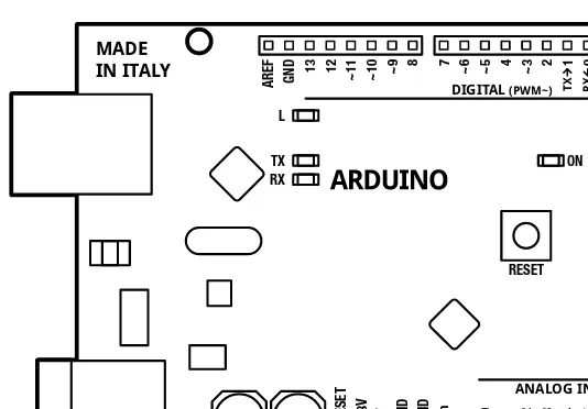
Figure 1-1. The Arduino Uno interface board, 2011
This microcontroller comes from a company called Atmel and the chip is known as an AVR. It is slow in modern terms, running at only 16Mhz with an 8-bit core, and has a very limited amount of available memory, with 32 kilobytes of storage and 2 kilobytes of random access memory. The interface board is known for its rather quirky design—just ask the die-hards about standardized pin spacing—but it also epitomizes the minimalist mantra of only making things as complicated as they absolutely need to be. Its design is not entirely new or revolutionary, beginning with a curious merger of two, off-the-shelf reference designs, one for an inexpensive microcontroller and the other for a USB-to-serial converter, with a handful of other useful components all wrapped up in a single board. Its predecessors include the venerable BASIC Stamp, which got its start as early as 1992, as well as the OOPic, Basic ATOM, BASIC-X24, and the PICAXE.
CHAPTER 1 ■ GETTING STARTED
Figure 1-2. LilyPad Arduino embroidery, courtesy Becky Stern, sternlab.org
This at least tells us a little bit about what kind of person the Arduino was originally designed for and about the hardware used in its design, but these things alone do not begin to account for the huge degree of success enjoyed by the Arduino as a whole. To get a sense for this popularity, we need to look at the larger Arduino ecosystem and how some fairly divergent parts came together to create a
movement.
The Arduino Ecosystem
The Arduino is not just one simple thing making it a little hard to define. It is a microcontroller platform, an open-source design that encourages modification and reuse, a community that has embraced and grown up around the Arduino, and a new crop of projects and devices that can trace their lineage to the Arduino and have in return contributed back to the development of various aspects of the entire Arduino ecosystem.
The Arduino Platform
CHAPTER 1 ■ GETTING STARTED
port and controller for easily communicating with your computer. This USB connectivity and friendly sockets for hookup wires to easily plug in to, contribute to the high level of usability in the interface board design.
Equally important to this ecosystem is the Arduino development environment, a program based on the Processing development environment (http://processing.org) that you use to write, edit, compile, and upload your Arduino source code to the interface board. The Arduino team made the general assumption that people don’t really care about the myriad of technical specifics involved with microcontroller architecture—they just want it to do something cool. With that in mind, the Arduino development environment wraps up some of the more techie parts of programming AVR
microcontrollers into a nice, simple library of Arduino-specific commands that are easier to use and easier to understand, and built right into every sketch written for the Arduino. This development environment is so versatile, that an Arduino interface board is not even needed to use it. Instead, we can use the very same AVR microcontroller as is built onto the interface board, but in an entirely different device—such as the example shown in Figure 1-3 of a microcontroller on a breadboard that has been programmed with an Arduino sketch.
Figure 1-3. Arduino compatible AVR microcontroller on breadboard
Finally, we are brought to the Arduino bootloader, a little chunk of code residing on the microcontroller that allows it to be easily programmed with a simple serial connection rather than cranky, external hardware. As long as the bootloader has been programmed onto the microcontroller beforehand, we can use that chip in whatever device we choose, such as the breadboard in Figure 1-3, and still write code for it using the rest of the Arduino platform. It helps if we use one of the
CHAPTER 1 ■ GETTING STARTED
Open-Source Hardware
The Arduino platform is itself pretty useful for microcontroller projects, but that alone is not enough to propel the popularity and widespread adoption of the platform. Instead of closing the design of the interface board and development environment, the entire Arduino project is deeply entrenched in the emerging practice of open-source hardware. Unlike open-source software, of which Linux is usually the often-cited example, open-source hardware seeks collaboration where physical objects are the outcome. It engages a distributed model of hardware development with contributors generally residing in different parts of the world. Rather than closed systems, open source projects allow an individual freedom to access the source files of a design, make improvements, and redistribute these improvements to a larger community.
The Arduino ecosystem fundamentally embodies this aspiration for openness in design, architecture, collaboration, and philosophy. You can see it for yourself as all of the design files, schematics, and software are freely available to download, use, modify, remake, and even resell. What started as a seemingly serendipitous decision to open the Arduino design and software to the greater community, spurred by the closing of the design school where the Arduino team was first formed, has lead to an entirely new movement in design. The practice of contributors having the liberty to use these designs freely (free as in speech) and with no obligation to buy anything (free as in beer) helps make the Arduino as endearing as a collection of silicon and copper can be. Not to mention that this creative feedback loop ensures that every inspired innovation derived from the Arduino platform is met with ever more imaginative uses for even more new things.
Community
CHAPTER 1 ■GETTING STARTED
Figure 1-4. Soldering Workshop, Maker Faire, San Mateo, CA, 2011, courtesy SparkFun Electronics
Community engagement for a project like the Arduino is essential for the success or failure of the project. Fortuitous timing also helped in that the Arduino came to the scene at the same time that the return of the Maker and DIY movements also began again. This ever-increasing new crop of makers means that you never have to look hard to find willing co-conspirators to help on anything open source; whether it’s through pockets of helpful individuals in the interweb or your neighborhood hacker space, help is never that far away.
Arduinoland
This community-driven research and development seems to have a magical effect on any project to come out of the wake of the Arduino, and this proverbial kingdom of mystical wonder is something I’m going to call Arduinoland. Maybe it’s because the hardware design works, is open, and is hackable, or maybe it’s because of a communal desire to build upon each other’s work, but whatever it is, in Arduinoland, soldering iron marvels, difficult to nearly impossible to pull off in a garage just ten years ago, seem to happen every day. Anything from interactive electronic textiles, autonomous flying aircraft, networked beer keg refrigerators, photographic missions to near space, and immersive architectural installations have all sprouted from this open Arduino ecosystem.
CHAPTER 1 ■ GETTING STARTED
Figure 1-5. MakerBot CupCake 3D printer with Arduino-compatible electronics
Or for all of those brown thumbs out there that can never seem to water their house plants when it’s most needed, a team of New York University students developed a tweeting plant moisture meter called Botanicalls, shown in Figure 1-6. Based on the Arduino reference design, combined with an off-the-shelf Ethernet module and a simple moisture probe all wrapped up in a leafy-green circuit board, the
CHAPTER 1 ■ GETTING STARTED
Figure 1-6. Botanicalls Arduino-based tweeting plant water meter, courtesy Botanicalls
These projects and many others have all benefited from the rapid development and reliable longevity brought to you by Arduinoland and the hard work put in by the Arduino team and community at large to create an open architecture that enables continued and accelerated growth and creativity.
Arduino is C… Mostly
In addition to the various aspects of the diverse Arduino ecosystem, we have the programming language of the Arduino platform, which is the central focus of this book. The core language used in the Arduino development environment is the C computer programming language first developed at the research institute of Bell Laboratories in the early 1970s for use with the UNIX operating system. C uses a procedural language syntax that needs to be processed by a compiler to map human-readable code to machine instructions. The long-standing popularity of C lends the Arduino some of its heritage, but the code that we are writing in this book is only mostly C.
Because there are aspects of the C language that look like it was written by dyslexic aliens, and with the language sometimes accused of being overly cryptic and difficult for beginners to pick up, the Arduino team has developed the standard Arduino library that provides a simple and targeted set of functions that make programming the Arduino interface board about as easy as it can get. Now, these libraries are themselves actually C++, itself a subset of the original C language, but we really don’t need to go there.
CHAPTER 1 ■ GETTING STARTED
Arduino C. To illustrate this point, Listings 1-1 and 1-2 provide two examples of the same source code to blink the onboard LED connected to digital pin 13.
Listing 1-1. Blink LED with avr-libc
#include <avr/io.h>
Listing 1-2. Blink LED with Arduino
void setup() {
These two different listings show two functionally identical sketches, one written with the Arduino library and one written without. The really nifty thing here is that, if you want to geek out, the Arduino development environment is fully compatible and extensible using C/C++ code written using the avr-libc library, a subset of the standard C library, and the GCC compiler, both written for Atmel’s standard 8-bit AVR microcontrollers. Listing 1-1 is written with avr-libc while Listing 1-2 is written using the Arduino library. They both are compatible with the Arduino development environment and can be uploaded the same way to the Arduino board. The first example also consumes a fifth of the amount of memory as the second example, coming in at 210 bytes as opposed to 1010 bytes.
CHAPTER 1 ■ GETTING STARTED
What’s Needed
Now that we know why we are learning to write code and generally what this platform offers, we are going to need a little bit of hardware to complete the projects discussed in the rest of this book. Even though we will focus our discussions primarily on programming the Arduino, the hardware is what makes programming the Arduino so much fun. The best place to get started with prototyping electronic circuits with the Arduino is through one of the many starter kits available from various retailers for anywhere from $40 to $100 USD or about €30 to €70 EUR. SparkFun Electronics (www.sparkfun.com) offers the Starter Kit and Inventor’s Kit; Adafruit Industries (www.adafruit.com) the Budget Pack or Starter Pack; MAKEMagazine’s Maker SHED (www.makershed.com) with either a Getting Started Kit or the Mintronics Survival Pack; or the Arduino Store’s (http://store.arduino.cc) Workshop Kit. Figure 1-7 shows what this assembled kit might look like.
Figure 1-7. Getting started hardware kit
While each of these kits will have more or less what you need, Table 1-1 provides a simple shopping list of some of the specific hardware that we will use in the following pages, which you might want to purchase individually or at least check whether or not the kit you are considering contains these items. Prices are only approximate and are listed just to give you an idea on the costs.
CHAPTER 1 ■ GETTING STARTED
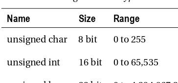
Table 1-1. Abbreviated Hardware List
Part
Description
Price (US / EUR)
Arduino Uno Microcontroller interface board $30/€22 USB cable A-B (often used for printers) for the Arduino Uno $4/€2 Solderless breadboard Either standard (400 tie points) or mini (170 tie points) $6/€4 Hookup wire Solid 22 AWG or pre-terminated M/M jumper wires $7/€5 Light emitting diodes Standard 5mm LEDs and common cathode RGB LEDs $10/€7 Resistors Handful each of 220, 330, 1K, 10K ohm ¼ watt or similar $10/€7 Capacitors A couple 1 and .1 microfarad capacitors of any variety $4/€3 Analog sensors 10K ohm trimpot, 10K ohm photocell, TMP36 temp sensor $4/€3 Switches Miniature momentary pushbuttons and tilt switches $3/€2 Transistors 2N2222 or 2N3904 NPN transistor or similar $1/€1
This minimal list of hardware will get you through about half of the book with other specific components necessary for the more advanced projects. When required, information on additional parts will be provided at the start of the chapter or section. While detailed in each chapter, these projects will include the use of temperature sensors, force/flex sensors, light sensors, accelerometers, wind sensors, liquid crystal displays, stepper motors, hobby servos, and other sorts of hardware. Although, rather than mandate a hefty toolbox of equipment, the projects and code will be written with as much flexibility as possible to allow the use of other sensors or actuators, depending on what you have available and your own personal interests and project ideas.
CHAPTER 1 ■ GETTING STARTED
Getting Up and Running
By this point, you have a pretty good sense for what the Arduino is, its history, and some of what you can do with it. It’s really exciting that with a few carefully written commands, which you will learn in the upcoming chapters, you can make things light up or move, sense the world around you, and generally make things more fun.
And now that you have some basic hardware in hand, including an Arduino interface board, it’s time to get up and running. We need to do the following before moving on to the next chapter:
1. Download and install the Arduino development environment
2. Connect the Arduino board with a USB cable and install drivers
3. Launch the Arduino application and open the Blink example
4. Select your board and serial port
5. Upload your first sketch
Don’t worry. It’s not that difficult to get going. In fact, it’s generally hard to go wrong, because it is nearly impossible to burn the house down or cut off an arm with an Arduino. And even if you wire up something wrong, it’s probably okay because the Arduino board is a tough little guy and can take some abuse. So don’t worry that you might mess something up. Of course, we are going to make some mistakes, but hopefully they will teach us something and we will become better programmers and makers because of it. So let’s get on with it.
Installing the Software
CHAPTER 1 ■ GETTING STARTED
Figure 1-8. Arduino software download page
From here download and install the latest version of the software for your particular operating system. Full installation instructions are available on the Getting Started page at http://arduino.cc/en/ Guide/HomePage. Linux can be a little tricky to get installed as of this writing, so be sure to carefully follow the instructions posted.
Connecting the Arduino
With the software installed, you should be able to connect your Arduino to the USB port on your computer using an A-B USB cable. The Arduino’s power indicator LED will light up on the board, letting us know that it has power and is ready to go. With a brand-new Arduino Uno, the first time that it powers up, the pin 13 LED marked L will begin to blink rapidly, letting us know that the board has been fully tested. On Windows-based PCs or older Arduino boards, it is necessary to install a driver for the
CHAPTER 1 ■ GETTING STARTED
Figure 1-9. Installing drivers on Windows 7
Opening a Sketch
Now you can launch the Arduino development environment. This will bring up an empty window if this is your first time out. Open an example sketch by navigating to the File menu ➤ Examples ➤ 1.Basics and select the sketch named Blink, as shown in Figure 1-10. You should now see a very simple example sketch for blinking the onboard LED once every second.
CHAPTER 1 ■ GETTING STARTED
Selecting the Board and Serial Port
Before we can upload our sample sketch, we need to select the correct board type and serial port that the board is attached to on our computer. Setting the correct board can be done in the Tools ➤ Board menu by selecting Arduino Uno or one of the other corresponding board names, as shown in Figure 1-11.
Figure 1-11. Selecting board type
Next, we need to choose the correct serial port under the Tools ➤ Serial Port menu, as shown in Figure 1-12. This port should be named COM3, or something similar, on a Windows PC; or something like
/dev/tty.usbmodem or /dev.tty.usbserial on the Mac.
CHAPTER 1 ■GETTING STARTED
Uploading a Sketch
Once you have selected the proper board and serial port, it’s time for the fun part. To upload a sketch onto the Arduino board, simply hit the Upload button on the toolbar, as shown in Figure 1-13. The onboard LEDs marked RX and TX will blink furiously and you will receive a message in the status bar that says, “Done uploading.” That’s all there is to it!
Figure 1-13. Uploading a sketch to the Arduino board
Summary
With all the installing, connecting, and uploading done and out of the way, you should now have a blinking LED on your Arduino Uno. That’s not to say you already fully understand how it all works— because that would kind of defeat the entire purpose of this book. But now that we’ve got something to blink and know that we can make it work, we might as well jump into learning the basics of
C H A P T E R 2
Sketching in Code
In the last chapter, we managed to get our first sketch up and running with the famous Blink sketch, otherwise known as the “Hello world” example. This is often a good place to start because it has a long-standing tradition as the first program to write when learning a new language. In the case of
programming hardware, we generally use the LED to blink hello. While that is a good beginning, we want to quickly get to some of the more interesting aspects of Arduino C, beginning with the focus of this chapter: the fundamental mechanics and control structures of sketching Arduino code. Our first project, RGB Blink, will explore the basic structure, syntax, and functions necessary for controlling the output of a three-color LED, taking our blinking LED to the next level.
We’ll start with a primer on what sketching means and how we can put the philosophy of sketching in code to use. As we will do throughout this book, we will then jump right into our project example and once you have this project wired up and the sketch uploaded to your Arduino board, we’ll back up and further explain how the sketch works and discuss most of the elements used in the project. In this way, when we look at each of the individual concepts in the chapter, you’ll already know how they were put to use. In this chapter, we’ll have a look at the basic anatomy of our project sketch and discuss how and why Arduino C does what it does. Don’t worry if it doesn’t make a tremendous amount of sense in the beginning, just work through it and it should get clearer as you go along.
What’s needed for this chapter:
• Arduino Uno
• 5mm RGB LED with common cathode
• 1x 330 ohm and 2x 220 ohm ¼ watt resistors or similar • Hookup wires
• Solderless breadboard
What is Sketching in Code?
CHAPTER 2 ■ SKETCHING IN CODE
So often, an idea in one of my classes begins with the simple words, “Wouldn’t it be cool if …?” Quickly sketching out these ideas serves as a way to conceptualize this moment of inspiration. Writing code can be just like this; it is after all a creative process used to solve specific problems. Sketching implies a sense of directness in the application of materials, like a pencil to a piece of paper. The Arduino development environment takes this same approach to making code as simple and direct as is possible. It is also why we will begin with simple sketches that quickly get you making something right away rather than bogging down in page after page of complex theory or algorithms.
When sketching in code, it’s okay to write bad code. You won’t hurt anything. As long as you get in there and start somewhere, as doing anything is always better than doing nothing. Making mistakes and learning what does work and what doesn’t, is an important part of learning anything new. In our sketchbook, we will start with simple source code, the basic instructions that tell the Arduino what it should do, along with basic hardware, starting small and working our way through to more involved examples.
You should freely experiment with every example, changing values, and piecing things together in unexpected ways to see what happens. Don’t be discouraged if it doesn’t work the first time; stick with it and it will get clearer with time. Testing and iterations are important parts of successfully writing code. So, change existing code or write some new code to establish a basic framework and then verify that your changes compile correctly. Work in incremental steps one addition at a time as you add to this basic framework for your code so that when you finally have something substantial, you can load it on to the interface board to see what happens. If something didn’t quite work as expected, all you need to do is undo that last incremental step. In this way it’s a good idea when you make changes, to only change one thing at a time before verifying that it still works before moving on to the next change.
Project 1: RGB Blink
CHAPTER 2 ■ SKETCHING IN CODE
BLUE
MAGENTA
GREEN
YELLOW
RED CYAN
WHITE
Figure 2-1. RGB color wheel
The particular LED we will be using is actually three separate LEDs—in the three primary colors of red, green, and blue—in one component package. Additionally, this LED is a common cathode type, meaning that the three LEDs share a common cathode pin, or connection to ground. This pin is the longest of the four pins coming out of the LED. We will connect each of the other three pins to the Arduino board through current limiting resistors, using hookup wires and a solderless breadboard.
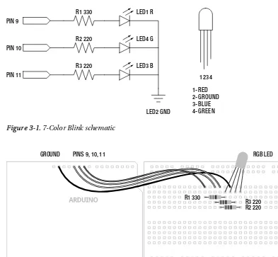
To get an approximately equal or balanced output from each LED, we will use a 330 ohm resistor (ohm is a unit of measurement for resistance) connected to the red LED, or leg 1 of the RGB LED, and 220 ohm resistors to the other two, legs 3 and 4. If you don’t have these resistors on hand, you can use the values 100 and 150 ohm or others that are close enough in value, anywhere between 100 ohms and 1 kilohm. If you use the same values for each color that’s okay too, but each color’s brightness might not be as closely matched. Some RGB LEDs are different from others so double-check the data sheet or product description as your mileage may vary. Refer to the following schematic and illustration for how to wire up this circuit.
Hooking It Up
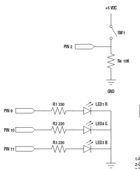
For the projects in this book, we will follow a couple of diagrams that show in different ways how the hardware goes together. We begin with a schematic, like the one in Figure 2-2, which is basically a simple drawing that shows in the most direct way possible how to make a circuit with lines that connect simple, abstracted symbols for the electrical components. Where things get placed in a schematic is rarely where they end up in our actual physical circuit—it’s just a way to show how one thing connects to another. Because schematics can be rather abstract, we will also include an illustration, like the one in Figure 2-3, showing one way that the finished circuit might look on the breadboard and how it connects to the Arduino board.
CHAPTER 2 ■ SKETCHING IN CODE
R1 330
R2 220
R3 220
LED1 R
LED4 G
LED3 B
LED2 GND PIN 9
PIN 10
PIN 11 1234
1-RED 2-GROUND 3-BLUE 4-GREEN
Figure 2-2. RGB Blink schematic
PINS 9, 10, 11
GROUND RGB LED
R1 330
R3 220 R2 220
Figure 2-3. RGB Blink illustration
Uploading the Source Code
CHAPTER 2 ■ SKETCHING IN CODE
Listing 2-1. RGB Blink Source Code
/* Project 1: RGB Blinky
Uses a single RGB LED to cycle through three colors. */ digitalWrite(10, HIGH); // turns on green digitalWrite(9, LOW); // turns off red
Our first project sketch takes the Blink example that we uploaded in the first chapter and builds on it by adding the additional two colors available in our RGB LED, connected to pins 9, 10, and 11 rather than the built-in LED on pin 13, to blink each of the three colors in turn. As I will explain in this chapter, there are two groups of code in this sketch called functions grouped by matching curly braces, { }, each named setup() and loop()—ignore the keyword void for the time being. We use setup() to configure the state of input and output pins, as well as other actions that we only need to run once. Conversely, loop()
will perform whatever actions are inside of it over and over again for an eternity, assuming limitless power as a prerequisite. Each line of code is executed inside a function, in order, from the top to the bottom. Inside the loop() function, when the last line of code is reached the function will repeat, beginning again with the first line of the loop() function.
Inside of each of these functions are statements that can include calls to other functions, such as
pinMode(), digitalWrite(), and delay(). The function pinMode() is used to set a specific pin to either
INPUT or OUTPUT. digitalWrite() is used to set the state of an output pin to HIGH or LOW, effectively used here to turn on or off an LED. The last function, delay(), does as it’s named and delays the program for a specified number of milliseconds. We will spend the rest of our time together looking at these and other functions and statements that we will use when writing code for the Arduino platform, but first let’s start with the basic structure of Arduino C.
The Structure of Arduino C
CHAPTER 2 ■ SKETCHING IN CODE
points of how sketches are organized and generally work and will apply to every sketch that we might write, not just our previous example. We will get to more on the specifics of functions and statements, including their syntax and parameters, a little later.
To begin with, Arduino C follows a set of rules that govern syntax and structure and tell the interface board what to do. Some of these rules are inherited from C and others have been put into place by the Arduino development team to simplify usage for beginners. C is a top-down structural programming language, meaning that lines of code are executed in order from the top of the program until it reaches the end at the bottom. We will adopt this top-down method in our analysis of the sketch for Project 1 to discuss the major points of the Arduino programming syntax and structure, beginning with our first lines of code.
Using Comments
Looking at our first example, the first three lines contain a small descriptive block of text that we refer to as comments. Comments are areas of text that are ignored by the compiler, but provide useful notes and documentation that give us a little extra information about the sketch to make the code easier to
understand for us humans. Use them to provide information about the project that the sketch is written for, about what certain variables do, what information a function needs to work properly, or what will happen if some part of the code is changed. Because comments take up no memory space on the Arduino board, they should be used generously throughout your sketch and are one of those good habits to have that should be adopted early on. Other people, including your future self, will be happy and thank you. Here’s our example:
/* Project 1: RGB Blinky
Uses a single RGB LED to cycle through three colors. */
This is an example of block comments. Anything in between the characters /* and */ are completely ignored and do not affect the outcome of the program. Block comments can be stretched across multiple lines, creating blocks of information, but need to be balanced with /* at the beginning to tell the compiler to ignore the following text until the compiler reaches the closing characters, */. The Arduino development environment conveniently changes comments to a grey color once they have been properly registered. This lets you know that you have entered comments properly or that you still need to close block comments (because your entire sketch suddenly became grey).
In addition to block comments, a second similar form of comments, called line comments, are used throughout the example sketch. Line comments are any line of text that begin with the characters
// and automatically end with the next line of code. Unlike block comments, line comments do not need closing characters and are often used at the end of a statement to provide a little more information about what that line does. This is the case in our first line comment in the previous example, as follows:
// sets digital pins as outputs
Both types of comments are also pretty useful for disabling parts of a sketch for testing and debugging. Just “comment out” an offending line to see what happens in your code. It’s also helpful to make a change in a part of the code but leave the old code in place using comments just in case you want to go back to it later. Take for example the following line:
digitalWrite(10, HIGH);
CHAPTER 2 ■ SKETCHING IN CODE
Alternatively, although not necessarily any clearer, the value could be changed using the following method:
digitalWrite(13 /*10*/, HIGH);
In this example, the value 10 is made into a comment using block comments in the middle of the line, and is, therefore, ignored by the compiler, but leaves it behind just in case you forget the old value. Once the integer value 10 has been hidden from the compiler, the integer 13 will become the new value for this statement. Keep in mind that whenever a section of code is commented out, it will only take effect the next time the sketch is uploaded to the Arduino board.
Line comments work for disabling single lines of code, but it would begin to be quite tedious to place line comments at the beginning of every line in a large block of code that needed to be temporarily ignored. Instead, place block comments around the whole section to be ignored, with /* at the
beginning and */ at the end of the block of code to make the compiler ignore it.
■
Note This won’t work if somewhere in your block of code you have another set of block comments, as it is not
possible to nest block comments inside of one another. In this case, you might have to change the inner block
comments to line comments or make some other modifications.
Comments are tremendously useful to the programmer and anyone reading your code, but they can sometimes get in the way, especially if you’re trying to write a book. For this reason, after our initial project here, we will no longer comment our code on a line-by-line basis. Yes, that may sound a little like, “do as I say, not as I do,” but I hope that it will make the discussion about particular concepts that much clearer without the added verbiage. If necessary to unpack a tricky line, we might add them in there for extra clarity.
Basic Functions
The C programming language is broken down into blocks of code called functions that form the main building blocks of any program. In this project we have two functions, setup() and loop(), each containing statements that do specific actions performed in order from top to bottom. As a requirement of the Arduino library, every sketch must at the very least contain both a setup() and loop() function in order to operate, even if they are empty. The following is technically a complete and working Arduino sketch, although it doesn’t do much:
void setup() { }
void loop() { }
CHAPTER 2 ■ SKETCHING IN CODE
void setup() { pinMode(9, OUTPUT); pinMode(10, OUTPUT); pinMode(11, OUTPUT); }
Starting at the beginning, we specify the function’s data type, in this case void, which is not terribly important for the moment, followed by the function’s name, setup, an opening and closing parenthesis,
( ), and a block of code bounded on either side with opening and closing curly braces, { }. The three lines of code inside the curly braces are examples of statements used to set up the state of the digital pins on the Arduino interface board. Specifically, we’re telling the Arduino that pins 9, 10, and 11 should be used as outputs and that we intend to use them a little later on in the sketch.
Of these two functions, the setup() function is called only once at the beginning of our sketch and is used for setting up various aspects of the Arduino board for running our code. A function call is another way of saying that the function, and all of the functions contained within it, is executed in the order they are listed. Examples of using the setup() function might also include establishing serial
communications, making initial sensor readings, or running certain tasks that are only needed one time. This function will always run once, immediately after powering up or resetting the Arduino board.
■
Note Anytime we discuss a function in this book, we will use a pair of parenthesis after its name to help
distinguish functions from things like variables. As an example,
assignValuerefers to a variable (more on these in
a moment) where
assignValue()refers to a function call.
The second function, loop(), makes it possible for your sketch to run continuously, and begins after the last statement in the setup() function has finished executing. Once the Arduino has completed its statements in order, reaching the end of the statements in the loop() function, it will, appropriately enough, loop back to the top of the loop() function and begin again, ad infinitum. Chances are this is where the bulk of your Arduino sketches will reside. Later in this book, we will investigate ways to manipulate the flow of the program and even demonstrate some methods for bouncing information back and forth between functions of your own creation.
■
Note When the Arduino runs a sketch, it starts at the top and works its way towards the bottom. This is called
program flow and refers to the order that the statements are executed. Much like the way the
loop()function
continuously repeats when it reaches the end of its statements, there are other ways to modify the program flow,
which will be discussed later.
Statements and Syntax
CHAPTER 2 ■ SKETCHING IN CODE
assigning values to variables, or performing arithmetic operations or comparisons. In our first project, anything in between the curly braces { } is a statement; take the following, for example:
digitalWrite(9, HIGH);
This line of code is a statement that calls one of the Arduino library’s built-in functions named
digitalWrite(), which is used to turn on or off one of the Arduino digital pins previously configured as an output. We pass this function two pieces of information that it needs to do its job: the number of the pin and the state that we want the pin to be in. These additional parameters, specific to each function, are called arguments and are found inside the left and right parenthesis, with multiple arguments separated by commas. In this example, we are telling the Arduino environment to turn on digital pin 9 of the Arduino interface board, as explained later.
There are two kinds of statements used in programming C: simple statements, including the most recent example, as well as compound statements. Simple statements include function calls, such as our earlier call to digitalWrite(), assignment statements, and arithmetic operations and are always
terminated with a semicolon. Semicolons ( ; ) are used to separate one simple statement from another so that the development environment can tell them apart. Forgetting to end a simple statement with a semicolon will result in one of the most common errors in the Arduino development environment. The following are a few examples of simple statements:
delay(1000);
digitalWrite(11, HIGH);
int myValue = 0;
myValue = 150 + 150;
Compound statements are made up of several lines of code that include other statements. Functions, such as setup() and loop(), are in effect compound statements. The if statement, covered in greater detail later in this book, is another form of a compound statement. A common example of the
if statement would look like the following:
if (pin2 == HIGH) { digitalWrite(13, HIGH); }
This statement will check the condition of the variable pin2 and will perform the following enclosed statements, to turn pin 13 on, if the variable meets the defined condition, in this case if the state of pin 2 is equal to HIGH. In this example, we see that compound statements use curly braces, { }, to enclose one or more statements within it, creating a continuous block of code. Curly braces must be used in
matching pairs and can encompass as many other statements, both simple and compound, as necessary.
While our example works fine, curly braces are only really needed by the structure of multi-line compound statements. If, as in the most recent example, the conditional statement only includes one other simple statement, the complex statement could be rewritten as a simple statement by removing the curly braces, as in the following syntax:
CHAPTER 2 ■SKETCHING IN CODE
This example is functionally the same as the one prior to it, although it saves us some real estate on our screen and debatably makes the code easier to read. To say it another way, curly braces are useful for enclosing multiple statements in one continuous block of code, creating a compound statement while simple statements use the semicolon at the end of each single line. Remember that simple statements inside of compound statements still need to end with semicolons.
In these examples, you have also seen the application of the parenthesis, ( ), to enclose arguments in a function or, as we will later see in more depth, for isolating arithmetic and comparison operations. Parentheses are used in pairs, so don’t forget to close them off. The loop() function has nothing inside its parenthesis because no data is being passed to or from the function (more on this later). On the other hand, the example of digitalWrite(9, HIGH) passes two values to and from the digitalWrite()
function, in this case the physical pin number on the interface board and its condition assignment. We have also used the parenthesis in separating a comparison operation in the case of if (pin2 == HIGH)
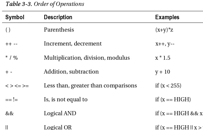
where we are testing the condition of pin2 against the constant HIGH. In arithmetic, parenthesis are also used to alter the order of operations as in (2 +2) * 10, although we will get to comparison and
arithmetic operations in more detail momentarily.
Verifying and Uploading
Taking this concept of sketching to heart by tossing together some lines of code that we are still not fully up to speed on, we’ve got a sketch entered into the Arduino development environment and we think we have all the syntax and statements correct, but now what? In the last chapter, we blindy uploaded our first sketch full of confidence, but how do we know if the code we entered will work or not before uploading it to the Arduino board? To answer these questions, let’s revisit uploading our sketch to the Arduino board, looking a little closer at the verifying and uploading process, including how to save your sketches and some of the common errors we might run into.
Verifying
As mentioned earlier, it is always a good idea to periodically verify a sketch that you’re working on, just to make sure that you’re on the right track, and even though this happens automatically before
CHAPTER 2 ■ SKETCHING IN CODE
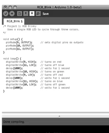
Figure 2-4. Verifying/compiling
Verifying will run the sketch through a process called compiling, where the development environment takes the Arduino C code that we have written and translates it into a binary format that the actual microcontroller will understand. If all goes well, a note will appear at the bottom of the window that says, “Done compiling,” and you will be told the binary sketch size in bytes. If there is an error during the verification process, skip ahead and check out the section on common errors to see if you can figure out what went wrong. Once we have completed writing our sketch, verified it for errors, and everything completes successfully, we are ready to upload the sketch to the Arduino board; but before we do that, let’s save our hard work.
Saving
CHAPTER 2 ■ SKETCHING IN CODE
Figure 2-5. Saving
The Arduino development environment saves files in the default sketchbook folder named Arduino, usually found in your Documents folder. Sketch names must contain standard characters and numbers, however, they cannot begin with a number and cannot include a space character. Instead of spaces, we generally use the underscore ( _ ) to separate words in a file name. The development environment also stores the file in a folder of the same name that it will automatically generate if the folder is not already there. Once saved, we can access our sketch from the File ➤ Sketchbook menu.
Uploading
CHAPTER 2 ■ SKETCHING IN CODE
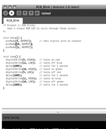
Figure 2-6. Uploading
Pressing the Upload button will send a signal to the Arduino microcontroller that tells it that it needs to stop what it’s doing and pay attention to the incoming code. At this point the LEDs marked RX/TX on the interface board will blink like mad, indicating that the code is being transferred to the board using serial communications through the transmitting (TX) and receiving (RX) of data using the built-in USB to Serial converter. When all is said and done, the notice bar will tell you when the upload is complete and your sketch will begin running momentarily.
Common Errors
You’ve just punched in your new sketch with eager anticipation to see that LED blink. You hit the Verify button, and after a long second or two, an error pops up. Now what?
CHAPTER 2 ■ SKETCHING IN CODE
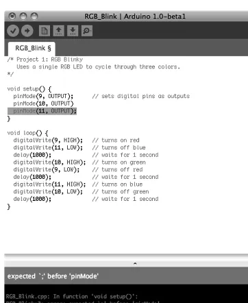
Figure 2-7. Compiler error
This can be a little disappointing at first, but hang in there, I’m sure you’ll figure it out. There are two general types of errors that we should be concerned with: hardware and syntax. Coming up are steps for troubleshooting these various error codes to help you get going again.
General hardware errors occur because something does not match the hardware you have or a connection isn’t made correctly, as in the following example errors:
Serial port not found.
Problem uploading to board.
First, check that your board is connected to your computer and is indicating good power with a lit LED marked ON. With this verified, next check that the correct serial port and the proper board type have both been selected under the Tools menu. If the USB cable is not connected or the wrong serial port has been selected, the development environment will offer to connect using a different serial port. Sometimes a more serious hardware failure will generate similar errors and you will need to talk to your reseller to iron these problems out.
Other types of hardware errors might show up as something not working the way you think it should because of a bad connection. In our example project, you would expect the LED to first blink red, then green, and then blue; but yours doesn’t light up red for some reason. This type of error comes from not wiring the components correctly, reversing the direction of certain parts like LEDs, or having the wires go to the wrong pins. This can be easily fixed by carefully going back over the hardware circuit, as shown in the schematic and illustration, to find out where something went wrong. It’s even a good idea to have another pair of eyes look over it just in case they see something that you missed.
CHAPTER 2 ■ SKETCHING IN CODE
expected ‘;’ before…
expected ‘)’ before…
expected ‘}’ before…
The Arduino development environment will generally give you a pretty good idea where to look for this problem by moving the cursor near the problematic code and highlighting the code near where the error was found, so you can fix it by replacing the missing character before trying to verify the code again.
■
Note Remember that at the end of every simple statement a semicolon is needed to separate one statement
from the next. Also, all parenthesis, curly braces, and block comments need to be matched in pairs.
Many syntax errors stem from Arduino C being case sensitive. In a case sensitive language, whether a letter is uppercase or lowercase must match exactly between what is entered and the syntax of the function, variable, or other statement being used. When writing Arduino sketches, there is a big difference between pinmode(), pinMode(), and PINMODE()—only one of these will actually work. The following are some examples of errors relating to case:
‘pinmode’ was not declared in this scope
‘high’ was not declared in this scope
These syntactical mistakes are examples of using the wrong case commonly when calling functions or using variables or constants. Look in the highlighted line of code for where you might have mistakenly typed high instead of HIGH, output instead of OUTPUT, pinmode instead of pinMode, or any other instances that are case sensitive.
No matter the error, just take a breath and think it through. I’m sure you will find it in no time. Writing code has a funny way of needing to be extremely logical and literal. If you are still having problems getting it going, you might turn to the generally helpful Arduino Forums at
http://arduino.cc/forum.
Summary
CHAPTER 2 ■ SKETCHING IN CODE
C H A P T E R 3
Working with Variables
In our last project, there is nothing in the sketch except for our comments that helps us to identify which color LED is connected to which pin on the Arduino board, or, for that matter, what color we are turning on or off at any given time in the code. We would just have to remember that the number 9 in the line
digitalWrite(9, HIGH); refers to the Arduino pin 9 that the red LED is connected to. Rather than trying to remember these things, because honestly we will forget or the next person we share our code with will have no clue, there is a better way to write our code using something called variables.
In this chapter, we will revisit the last project, pulling from our magic hat to create seven colors out of our three-color LED as a way to talk about the many uses for variables and how we can put them to work for us. We will also look at a few ways to manipulate variables using several different kinds of operators and how they work. For this new project, we will use the same hardware from the last chapter, but it might be a good idea to briefly mention them here again.
What’s needed for this chapter:
• Arduino Uno
• 5mm RGB LED with common cathode
• 1x 330 ohm and 2x 220 ohm ¼ watt resistors or similar • Hookup wires
• Solderless breadboard
Project 2: 7-Color Blink
If you’ll remember the RGB color wheel in Figure 2-1 of the last chapter, we can mix red, green, and blue light to create millions of different colors. For our next project, we will take the simple three-color sketch from the last chapter and improve upon it by introducing simple color mixing to get seven colors, while pausing for a little longer on white for effect. This will give us an opportunity to introduce working with variables and demonstrate some basic operations, as well.
Hooking It Up
CHAPTER 3 ■ WORKING WITH VARIABLES
R1 330
R2 220
R3 220
LED1 R
LED4 G
LED3 B
LED2 GND PIN 9
PIN 10
PIN 11 1234
1-RED 2-GROUND 3-BLUE 4-GREEN
Figure 3-1. 7-Color Blink schematic
PINS 9, 10, 11
GROUND RGB LED
R1 330
R3 220 R2 220
Figure 3-2. 7-Color Blink illustration
Uploading the Source Code
CHAPTER 3 ■ WORKING WITH VARIABLES
digitalWrite(green, HIGH); // yellow delay(time);
To kick things off, we start our sketch with a block of code that defines each of the variables that will be used in our code. In this way we will know, for example, that the red LED is connected to pin 9 and the time delay between colors is 1000 milliseconds, or 1 second. If we wanted to change any of these values, to set different pin numbers for the RGB LED or to increase or decrease the delay time, we would only have to change the value in one single location, speeding up changes to the sketch and making it that much easier to understand. This will become more important later on when our sketches begin to do more interesting things with our variables, but for now let’s look at the following first line of code in more detail:
CHAPTER 3 ■WORKING WITH VARIABLES
This line declares that the first variable is named red; identifies the variable’s data type as an integer, or int; and then tells the compiler that this variable should stay constant using the const modifier. Finally, this one line of code will also assign the numerical value 9 to the variable named red. In this way, the keywords red, green, blue are all variable names that we made up to identify the pin that each color of the RGB LED is connected to, while time is a variable to store the time period that each color stays on for, and multiple will be used to delay for a longer period on white just to give it a little emphasis.
Later in the sketch, we substitute the numbers that might be found inside the various statements with the variable names that we set up earlier so that every time that name is called, the compiler knows to look up the appropriate value. By using variables in our code, the following two lines will be
functionally equivalent:
pinMode(red, OUTPUT);
pinMode(9, OUTPUT);
The rest of the code is just a slightly longer version of our last project sketch. In addition to red, green, and blue, you should now see yellow, cyan, magenta, and even white. Pretty nifty, huh? In addition to turning on and off each color of LED, we turn on two colors at the same time to make the intermediary colors, and all three colors to make white. Inside the loop() function, we begin with red, then add green to make yellow, turn off red to make green, add blue to make cyan, turn off green to make blue, turn on red to make magenta, and then turn on green to make white. At this point, we perform a compound operation to multiply the time delay with another variable called multiple to create a longer delay on the white color. We then reset our colors by turning off blue and green, leaving only red, perform another operation on the time delay to return it back to its original value, and then we start the loop all over again.
Now that we have seen variables in action, let’s look at them in much greater depth to find out how we can put them to work for us.
What’s a Variable?
The variables that we use in writing code are the very same variables that we learned about in school. Take the following equation for example:
a2
+ b2
= c2
I’m sure you’ve seen this before; it’s the Pythagorean theorem and it’s pretty useful for finding the length of one side of a right-angle triangle if we know any of the other two sides. The letters a, b, and c
are the names for numerical data, in this case the letter c is used for the hypotenuse while a and b are the other two sides of the triangle. We can also call these letters variables. Variables are quite simply containers for information. In programming, variables have a name that tells us what data the variable might contain and they have a type that determines what kind of information the variable can hold, and finally they have a value whether we know what it is or not.
CHAPTER 3 ■ WORKING WITH VARIABLES
Declaring Variables
When setting up a new variable, we need to at the very least determine two pieces of information: the variables data type and its name. This process is called declaring a variable where we will hold a place open in the Arduino’s memory to store our information. Declaring a variable is as simple as indicating the data type followed by a unique name for the variable. The following are some examples of simple variable declarations:
int x;
int myVariable;
int time;
The sort of data that can be stored in a variable, and what can be done with it, is determined by the variable’s data type. The data type that is chosen is very important later on when it affects what we can and cannot do with it. In the previous examples, we are declaring integer data types, signified by the int
keyword, a useful data type for numerical data. After establishing the data type, we need a clear variable name that tells us in plain English what the variable does. As a general rule of thumb, it should be descriptive, but not overly cumbersome. Take the following examples:
int r;
int red;
int redLEDConnectedToPin9;
Each of these three variable names is technically correct, but naming our variable red instead of the letter r is generally easier to understand. Single-letter variable names, with a few exceptions, are often harder to read and make sense of; for example, a lowercase l (L) looks an awful lot like the uppercase I
(I), or even the number 1 (1). The extreme case, redLEDConnectedToPin9, is generally too verbose and makes reading, as well as writing, the code somewhat tedious.
Where these previous examples simply declare the variable data type and variable name, it is also possible to assign a value to a variable when we declare it in a single statement. In our example sketch, we did this in the following line:
int red = 9;
Here we are declaring the variable named red as an integer data type and assigning the value 9 to that variable name using the assignment operator to be discussed shortly. While the Arduino compiler will still hold a place open in its memory for a variable even if we do not assign it a value, it is generally a good idea to assign a value in the variable declaration even if that value is 0.
Variable Names
CHAPTER 3 ■ WORKING WITH VARIABLES
myVariable, mYvAlUe, DELAY_TIME, and value1 are all valid names. Conversely, the variable names
1stValue, delay time, and time&money are not valid names for a variable.
Now some of these names may not be the most readable, which is why many Arduino programmers have adopted certain naming guidelines or conventions. Naming conventions are generally
controversial in programming circles, and they are not specifically required when defining your own unique names, but they can make code easier to read in the big scheme of things.
For example, we can have a variable name with multiple words but, because we cannot use spaces inside our variable name, we might want a way to separate each word to make the name easier to read. One possibility is to use an underscore between each word, as in red_led_connected_to_pin_9, a method usually favored by UNIX programmers. Instead, we will use the convention known as camelback notation, as in redLEDConnectedToPin9. Under this convention, the first letter of the first word will be lowercase while the first letter of each subsequent word will be capitalized with no space between each word. Take the following examples:
variable
myVariable
value1
tiltSwitchValue
It’s really your choice how you name your variables and you will often see both types in other people’s sketches, but we feel that camelback notation makes the code easier to read and matches the format the Arduino developers have decided upon for all of the built-in functions in the Arduino library. Likewise, it is the general convention that constants are sometimes written in all caps with underscores in between multiple words, as in the following examples, although we will not adhere strictly to this in naming our own constant variables.
HIGH
INPUT
BLUE_LED
■
Note Remember that the Arduino language is case-sensitive, so whatever style you adopt, you need to use it
consistently throughout your sketch. This also means that any predefined variables or function names that are
already a part of Arduino C must be used with exact capitalization.
One thing to keep in mind is that while there is no maximum or minimum length for variable names, extremely long names start to become rather tedious to type over and over. On the other hand, one-character names are often too cryptic. A few exceptions to this would be the lower case letter i, which is a commonly used variable to indicate an index along with the variable names j and k. Likewise,