Abstract— Existing secure RFID tags rely on digital
cryptographic primitives in the form of hashes and block ciphers, which lead to large system latencies, high tag power-consumption and large tag silicon area. In addition, existing passive RFID systems rely on simple coding and modulation schemes using narrowband radio frequencies, which can easily be eavesdropped or jammed. To address the above problems, we propose a new approach for secure passive RFIDs based on ultra wideband (UWB) communications. We adopt time-hopped pulse-position modulation (TH-PPM), in which the hopping sequence is known only to the reader and the tag. By adopting the hopping sequence as a secret parameter for the UWB communication link, eavesdropping of the communication is extremely difficult. Thus, we can avoid digital cryptography and support privacy directly at the physical-communication layer.
I. INTRODUCTION
ASSIVE RFID capture and reuse incoming radio-frequencies to power internal circuitry and to respond back to the RFID reader. The available RF power, equivalently the maximum distance, of the reader-transponder system is constrained at both sides of the link, either by regulations or else by technological limits. A typical example of an UHF (in 900 MHz band) tag can reach 2 m with a power budget of 150 μW for a tag and 500 mW for a transmitter [1]. Current systems implement a half-duplex link between a reader and a tag. A reader sends a power-carrying RF carrier to a tag, adding additional data by means of amplitude modulation. The reverse link, from a tag to a reader, is based on adaptive reflection (backscatter) of the phase of the incoming RF carrier, or on adaptive loading [2]. Current systems use a narrowband signal in both directions, with a bandwidth much smaller (a few 10’s kHz) than the carrier frequency (900 MHz). These existing communication schemes have been developed with simplicity in mind. They are susceptible to passive attacks such as eavesdropping
Manuscript received November 24, 2006.
Dong S. Ha is with the Electrical and Computer Engineering Department of Virginia Tech, VA 24061 USA (phone: 4942; fax: 540-231-3362; e-mail: [email protected]).
Patrick R. Schaumont is with the Electrical and Computer Engineering Department of Virginia Tech, VA 24061 USA (phone: 540-231-3553; fax: 540-231-3362; e-mail: [email protected]).
[3,4,8] as well as active attacks such as illegal readout [5].
In recent years, many schemes have been proposed to address the privacy issues related to such tags, as well to extend their application domain to include authentication besides detection [6,10,12,13]. All of these proposals are enhancements at either the protocol-level or the algorithm-level of the communications link. They assume implicitly that the communications link between a tag and a reader can be eavesdropped and thus that privacy must be guaranteed by the data link layer. Many of these proposals rely on digital block ciphers or hashes. It was shown that traditional digital cryptography can be implemented within typical implementation constraints of passive tags. Feldhofer presents an implementation of AES of
3,595 equivalent NAND gates that consumes 8.5 μA
[6]. This shows that symmetric-key implementations can meet area and power constraints of tags. A similar conclusion, made for the case of low-frequency tags (13.56MHz), can be found in [7]. However, the use of digital cryptography in a power- and silicon-area-constrained RFID tags comes with cost. The presence of digital ciphers in RFID tags increases their response-time. A high cycle count combined with a low operating frequency results in substantial computation times for these ciphers. For example, the AES implementation discussed in [6] requires 995 cycles. At a tag clock frequency of 1 MHz, one round of encryption takes close to 1 ms. The new Gen-2 tags take 1.6 ms to transmit a 128-bit tag [9]. Consequently, the tag encryption time is of the same order of the transmission time of the encrypted result. This latency reduces overall system throughput and may violate the constraints of the standard [6]. In addition, a tag’s computation and communication periods are clearly separated in time, making it easier to mount a power-analysis side-channel attack that focuses on the cipher [8].
Recent work in so-called ‘light-weight’ protocols tries to alleviate the requirements of encryption or even to eliminate them altogether. The HB+ protocol, for example, uses a protocol modeled after human
Replacing Cryptography with Ultra Wideband (UWB) Modulation
in Secure RFID
Dong Sam Ha, Senior Member, IEEE and Patrick R. Schaumont, Senior Member, IEEE
P
authentication [10]. It uses repeated challenges directly derived from the shared key K. Unfortunately; the HB+ protocol was not resistant against active attacks [11]. Using a man-in-the-middle attack, an attacker is able to reveal a single chosen key-bit per challenge-response iteration. Besides HB+, several other proposals have been presented recently, all of which use a cryptographic primitive (hash function or cipher). The hash-lock scheme from Sarma and Weis [12] uses the concept of a lock based on hash-functions. The YA-TRAP protocol from Tsudik [13] relies on time-stamping RFIDs and a hash function to prevent unauthorized tracking. Most existing secure RFID tags therefore still rely on cryptographic primitives, either in the reader or else in the tag. This is unavoidable as current systems implicitly assume that communications can be eavesdropped at will.
In this paper, we propose to use physical communications as a new dimension in the reader-tag system design to implement those secure protocols. We propose to secure physical communications based on ultra-wideband (UWB) modulation and time-hopping. Rather than encrypting the tags’ identifier, we use a private modulation code, specifically time hopping sequence. Only a receiver who knows the hopping sequence is able to receive the overall message. Our approach offers the following benefits over existing secure RFID tags.
• UWB transmissions are very difficult to eavesdrop
because of their low power-level.
• Secure-UWB modulations do not require data
encryption. As will be seen later, eavesdropping on a 15-bit secret modulation code requires prohibitively powerful communications equipment, which is impractical.
• Secure-UWB tags have low latency, and are able to
respond much faster to a reader.
• UWB transmissions are more robust to interference
than narrowband transmissions. They are difficult to jam and allow multiple transmissions in the same band.
In this paper, we present a protocol for secure RFID tags based on a UWB modulation scheme and its implementation in the baseband signal processing. In Section 2, we briefly review the properties of ultra-wideband modulation, and discuss our proposed time-hopped pulse-position modulation. We also present the communications protocol between a tag and a reader. In Section 3, we present a baseband signal architecture for our tag. This includes discussions on a random number generator as well as a pulse-position modulator that drives the UWB pulse generator. In Section 4, we
summarize potential security risks of our approach, and in Section 5 we draw a conclusion on the proposed RFID system and point out open research issues.
II. ULTRA-WIDEBAND RFID
A. UWB communications
Since the FCC’s allocation of a UWB spectrum in the range of 3.1 GHz to 10.6 GHz in 2002, UWB has gained phenomenal interest in academia and industry [14]. Compared to traditional narrowband communication systems, UWB has several advantages including high data-rate, low average radiated power, and simple RF circuitry. Many of these potential advantages are a direct consequence of UWB’s large instantaneous bandwidth. Shannon’s theorem states that the channel capacity C is given as B log2(1+SNR),
where B is the bandwidth and SNR is the signal-to-noise ratio [15]. As the bandwidth B is much larger (on the order of several GHz) for UWB than for a narrowband signal, the SNR can be much smaller for UWB to achieve the same data rate. Therefore, UWB is often able to recover data, even if the signal power is close to the noise level. In other words, the presence of UWB signals is harder to detect than narrowband signals.
The IEEE 802.15 WPAN task group has recognized the potential of UWB for low data rate applications, and is in the process of standardizing the physical layer [16]. Hancke and Kuhn presented a paper on securing RFIDs using UWB, to the best of our knowledge, the only one so far on this topic [17]. They suggested measuring the signal propagation delay between an RFID and the reader using UWB. If the delay exceeds a certain bound, the system signals a possible attack.
pulse the first slot, and the third pulse the fourth slot in the figure. Like any other PPM, the position of a pulse within a time slot carries the information bit for TH-PPM. For example, a pulse aligned to the start of a slot represents logic 0 (Figure 1(b)). A pulse delayed by Δ with respect to the start of a time slot carries logic 1 (Figure 1(c)).
(a)
(b) (c)
slot = 1 slot = 4
bit-value = 0 bit-value = 1
Time
Δ slot = 2
Figure 1: Time-Hopped Pulse-Position Modulation
So far, time-hopping has been used in communications for two purposes; multiple access and/or spreading of the spectrum. We introduce a new application of time-hopping, which is to secure physical layer communications. This is possible as explained following. To demodulate extremely narrow UWB pulses, a receiver should correlate incoming pulse signals with a template signal. The time slot of an
incoming pulse is known a priori for a conventional
TH-PPM scheme. The receiver performs two correlations starting at two different instances, one at t=0 as for the case in Figure 1(b) expecting a logic value 0 for the incoming signal and the other at t= Δ as in Figure 1(c) expecting logic 1. One of the two correlation operations will capture the received signal energy, while the other one will only correlate noise. If the time slots of pulses are assigned in a pseudo random manner, the eavesdropper should perform correlations for all possible time slots. If the total number of time slots is sufficiently large, eavesdropping of TH-PPM communications is practically impossible.
B. Frame format for our RFID system
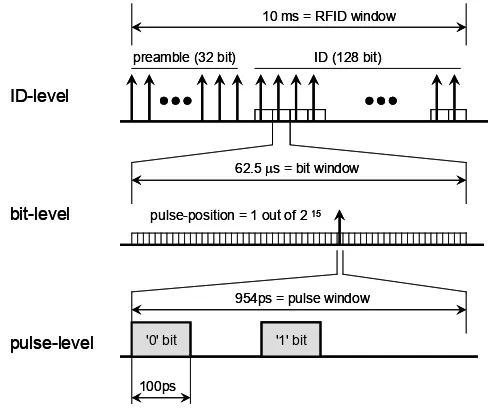
We now discuss the data framing for our secure RFID system. Figure 2 illustrates a superframe for the transmission of a single ID. The transmission completes within 10 ms, similar to present-day non-secure RFIDs. The superframe contains a 2 ms preamble and an 8 ms data-field. The preamble contains 32 known bits, which occupy the same time slot within each frame. The purpose of the preamble is
to synchronize the reader. Next, a pulse train of 16 bits for the initial state of the random number generator (which is omitted in the figure for simplicity) and 128 bits for the identifier of a tag follows. Each bit uses a different pseudorandom time slot within a frame. The period of a frame, i.e., time window of a single bit, is 62.5 μs, and a frame contains 216 (=65,536) time slots, each slot being 954 ps long. Among the available 65,536 time slots, a UWB pulse actually positions at the second half of the frame, and the first half of the frame, 32,768 time slots or 31.3 μs, serves as guard time. This slot length is long enough for a UWB pulse not to interfere with the pulse from the following time slot.
preamble (32 bit) ID (128 bit) 10 ms = RFID window
62.5 μs = bit window
pulse-position = 1 out of 2 15
954ps = pulse window
100ps
ID-level
bit-level
pulse-level '0' bit '1' bit
preamble (32 bit) ID (128 bit) 10 ms = RFID window
62.5 μs = bit window
pulse-position = 1 out of 2 15
954ps = pulse window
100ps
ID-level
bit-level
pulse-level '0' bit '1' bit
Figure 2: UWB frame format
III. ARCHITECTURE FOR AN ULTRA-WIDEBAND RFID
In this section we present an overview of the UWB-RFID tag architecture, including design of the digital baseband parts.
A. UWB-RFID tag architecture
transmitter is very small. For example, [19] presents a transmitter design that delivers a 40 MHz UWB pulse rate with 2 mW of power consumption. The pulse rate of 16 KHz adopted for our system is more than three orders of magnitude lower than that, which would push
average power consumption in the μW range. Lee and
et al. proposed a UWB pulse generator constructed of a simple logic circuit, in which glitches of digital logic are used as UWB pulses [20]. Such a low-power pulse generator would be suitable for the proposed system.
UWB Pulse Gen. PRNG
F
Preamble / Tag Memory
LFSR
Preamble / Tag Memory
LFSR
Preamble / Tag Memory
LFSR
Preamble / Tag Memory
LFSR
Figure 3: System architecture of the proposed UWB RFID tag
The pulse positions are decided by a programmable pseudo-random number generator (PRNG), which is based on a linear feedback shift register (LFSR). For the framing format shown in Figure 2, the PRNG generates a random number of 15 bits for a data bit. The PRNG operates in two modes: a preamble mode and a tag identifier mode. The PRNG generates a fixed known number, say 0, under the preamble mode. This enables the reader to synchronize with the tag clock. In
tag identifier mode, the PRNG generates a priori
known pseudorandom numbers to transmit from the data stored in the tag's memory.
The system clock for the tag is derived from the narrowband carrier, which eliminates the need for a clock generator for the tag. It also makes the tag clock in synchronous with the reader clock, which simplifies the clock synchronization for the reader. The frame format in Figure 2 requires a carrier frequency of 1,048 MHz, in which the period of a time slot is 954 ps. If we employ standard 900MHz UHF tags operating at 900 MHz, the period of the time slot should be increased slightly.
In the following, we discuss the operation and implementation of the PRNG and of the pulse-position modulator. Next, we discuss several aspects related to the system timing such as system reset and clock synchronization.
B. Programmable Linear Feedback Shift Register
A key characteristic of our system is that its security does not come from a cryptographic operation, but from the inability to detect TH-UWB signals for an eavesdropper. We propose the use of a programmable LFSR as a pseudo-random number generator. By itself, an LFSR is not very useful as a cryptographic algorithm: the linear properties of an LFSR make it relatively simple to predict the next-state from a given set of previous states. However, we do not rely on the cryptographic properties of an LFSR for our system, but rather on the pseudorandom properties of an LFSR sequence.
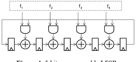
We require that each tag has its own pseudorandom time-hopped sequence to ensure that the reverse engineering of a single tag (e.g. reverse engineering a tag's integrated circuit) cannot be used on another tag. Therefore, we use a programmable LFSR as illustrated in Figure 4.
f1 f2 f3 f4
Figure 4: 5-bit programmable LFSR
Using a programmable feedback pattern, we can choose the LFSR polynomial, defined as
5
feedback-pattern. Our proposed architecture can support all possible sequences including m-sequences.
C. Pulse Position Modulator
The purpose of a pulse-position modulator (PPM) is to generate a required time delay to position a UWB pulse within a frame, i.e., a bit window. As mentioned earlier, a pulse appears only at the second half of a bit window, while the first half is used as a guard time. The guard time is necessary to ensure that two consecutive pulses are apart by at least 31.3 μs. The guard time allows the power harvesting circuit to recharge in between pulses, and it also avoids inter-symbol interference between two consecutive UWB pulses.
Within a 31.3 μs time window, the PPM has to
implement a resolution of 215 time steps, where a time step is 954 ps long, equivalently 1.048 GHz. A straightforward approach is to use a 15-bit counter running at 1.048 GHz, but this is a power-hungry solution. Figure 4 shows a distributed solution for the delay generation. The clock frequency of a stage i is running at two times the clock frequency of the stage
(i+1). The rightmost stage 0 runs at the clock
frequency of 1.048 GHz, while the leftmost stage 14 at
64 KHz. A stage i of the PPM chain delays the input
signal Ei by one clock period, if p[i] = 0, and two clock
periods if p[i] =1. So the total delay between Ein and
Eout ranges from 215-1 time steps (when P[14..0] =
00…0) to 216-2 time steps (when P[14…0] = 11…1).
The range ensures that a UWB pulse positions in the second half of a bit window. P[14..0] are the 15 bit UWB position information generated by the LFSR. The distributed solution minimizes the number of registers running at high clock speed, which saves power dissipation for the PPM.
An open issue is the average power consumption of the pulse-position modulator. Preliminary experiments
with 0.18 μm CMOS technology have shown that the
circuit in Figure 5 consumes almost 600 μW, with the very first stage at the highest clock consuming about
half of that (298 μW), and subsequent stages each
consuming half the power of the previous stage. Further reducing this power consumption is one of the key research issues for this design.
clk_in
Figure 5: Distributed pulse-position modulator
D. System Synchronization
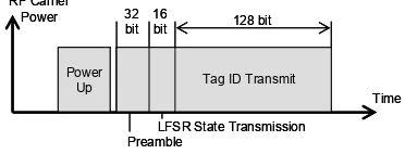
The synchronization between a tag and the reader goes through 4 phases as shown in Figure 6. The four phases include power-up, preamble, LFSR state transmission, and tag ID transmission. Each of these phases is described below.
Initially, the reader sends a narrowband RF carrier to the passive tag, which allows the tag to power up. The tag's internal power circuit brings the PLL to a stable state. The power-up stage requires a few milliseconds at most. When the reader is ready to query the tag, it temporarily interrupts the RF carrier. This small gap does not cause power-loss for the tag, but can be used to reset the system. As soon as the carrier comes back, the tag is reset and moves to the preamble phase.
Power
Figure 6: Tag-reader synchronization.
During the preamble, the tag transmits a known set of data bits, which starts as soon as the carrier is detected. The preamble data bits always occupy position 0 (more precisely, 215-1) in a bit-window, and
they are thus spaced 62.5 μs apart. During the
preamble phase, the reader is to synchronize with the tag clock, to identify the frame boundary, and to detect the end of the preamble phase.
to detect the carrier and send the first pulse. The processing time is fixed and known a priory, so it does not affect the window size of the synchronization time search. The signal flight time is determined by the distance between a reader and a tag and has a limited range. For example, the round trip flight time is 6.7 ns for a distance of 1 m between a reader and a tag, which is equal to 7 pulse windows (Refer to Figure 2.) As a result, we expect the reader to synchronize with the tag clock with a necessary precision within the first half of the preamble phase and to read the preamble data during the second half, so that the end of the preamble phase (equivalently the beginning of the following LFSR state transmission phase) can be detected within the preamble phase.
At the end of the pre-amble, the bit windows of the tag and the reader are synchronized, and the LFSR state transmission phase starts. During this phase, the tag transmits the state of the LFSR to the reader at position 0 in a time slot. In other words, the LFSR state is transmitted in the clear. Since the feedback connection pattern of the LFSR is known only to the tag and the reader, the state of the LFSR does not disclose the random number generation sequence. The initial state of the LFSR may change at each power up or be set to a fixed state. The former case can be used to discourage an attacker to experiment repeatedly to identify the feedback connection, and the latter one for simultaneous reading of multiple tags with the same feedback connection.
Up to this point, all the activities of the reader can be executed by an attacker as well. The next phase however, cannot be completed successfully unless the LFSR feedback pattern is known. In this final phase, the tag transmits each of the 128 bits of its memory, and the LFSR selects a different pulse-position for each bit.
IV. RISK ANALYSIS
We now consider the cost of eavesdropping (passive attack) and jamming (active attack) for the proposed approach.
A. Passive Attack
First, consider the case of eavesdropping. From the above description, it is clear that an attacker can fairly easy synchronize the eavesdropping system up to the LFSR state transmission phase. Thus, we assume that the initial state of the LFSR is known to the eavesdropper, and that only tag-internal information (tag memory-content and LFSR feedback pattern)
remain unknown.
Because the eavesdropper cannot derive the LFSR sequence from the state alone, an exhaustive search over all possible pulse positions in a bit window is required. This is an infeasible problem, as the following estimates show. Suppose that the eavesdropper performs a brute-force attack which captures every signal within the transmission window of the ID (8 ms). To capture enough energy of each UWB pulse (100 ps wide), about ten samples would be necessary. For each pulse window, the eavesdropper thus needs 20 samples (0-bit or 1-bit). For each bit window, he needs 32768*20 samples. And for the entire ID, he needs 128*32768*20 = 84 million samples. In addition, those samples need to be acquired within an 8 ms time period, which requires an equivalent A/D sample rate of 105 billion samples per second. This is not feasible with current technologies.
An alternative strategy would be to attack a certain fixed time slot, for example, always to read time slot 0
(more precisely, 215-1) of each bit-window, and
perform multiple RFID read operations until each pulse of 128 bits hits the time slot at least once. This would need, on average, 32,768 / 2 read operations for the example shown in Figure 2. We can thwart this attack by deactivating the RFID automatically after a certain number of reads, defined by its expected lifetime (presumably much smaller than 32,768 / 2 reads).
B. Active Attack
Active attacks, using jamming, are complex to implement as well. This requires disruption of the signal exactly at the position where an UWB pulse is located, and hence requires knowledge of the time hopping sequence. If the objective would be only to jam the signal, a transmitter should generate a distortion pulse at each possible pulse position. This requires a significant amount of transmission power in the GHz range, which is very expensive in hardware.
V. CONCLUSIONS AND FUTURE WORK
UWB is much cheaper in hardware and is complementary to traditional cryptography used in RFIDs.
The multiple access property of TH-PPM UWB can be explored for simultaneous reading of multiple tags, which can address the time-consuming process of reading one tag at a time for present RFID systems. Also, UWB has better propagation properties than traditional narrowband communications. We thus envisage UWB RFID to be useful in environments that are unsuited for narrow-band tags.
Further research is necessary to verify practicality of the proposed secure RFID system. First, the power budget should be analyzed to verify that the energy harvest from the narrowband receiver is sufficient to power necessary UWB circuits. Second, the strength of the security should be analyzed in conjunction with various methods of attacks. Third, as keys are hardwired for the proposed system, change and distribution of keys is more difficult than software based keys. An effective method for managing keys needs to be investigated as well.
ACKNOWLEDGEMENT
This work was partially supported by the National Science Foundation under Grant No. 0551652 for the first author and Grant No. 0644070 for the second author.
REFERENCES
[1] U. Karthaus, M. Fischer, “Fully Integrated Passive UHF RFID Transponder IC With 16.7-μW Minimum RF Input Power,” IEEE Transactions on Solid-State Circuits, 38(10):1602-1608, October 2003.
[2] K. Finkenzeller, “RFID Handbook: Radio Frequency Identification Fundamentals and Applications,” Chapter 4 – Physical Principles of RFID Systems, John Wiley & Sons, 1999.
[3] I. Kirshenbaum, A. Wool, “How to build a low-cost, extended-range RFID skimmer,” IACR eprint architecture 2006/054, online at http://eprint.iacr.org/2006/054.pdf.
[4] K. Mahaffey, M. McGovern, P. Simmonds, J. Callas, “Long Range RFID and its Security Implications,” presentation at BlackHat USA 2005, Las Vegas.
[5] L. Grunwald, “RFID and Smart Labels: Myths, Technology, and Hacks,” BlackHat USA 2004, Las Vegas, July 2004.
[6] M. Feldhofer, S. Dominikus, and J. Wolkerstorfer, “Strong authentication of RFID systems using the AES Algorithm,” Proc. of the 2004 Cryptographic Hardware and Embedded Systems workshop (CHES 2004), LNCS 3156, p 357-370, 2004.
[7] T. Lohmann, M. Schneider, C. Ruland, “Analysis of Power Constraints for Cryptographic Algorithms in Mid-Cost RFID Tags,” Seventh Smart Card Research and Advanced Application IFIP Conference (CARDIS 2006), LNCS 3928, p 278-288, 2006.
[8] Y. Oren, A. Shamir, “Power analysis of RFID tags,” online at http://www.wisdom.weizmann.ac.il/~yossio/rfid/.
[9] AutoID Center, “Draft protocol specification for a 900 MHz Class 0 Radio Frequency Identification Tag,” February 2003.
[10] A. Juels, S. Weis, “Authenticating Pervasive Devices with Human Protocols,” 25th Annual Cryptology Conference (CRYPTO05), August 2005, Santa Barbara, CA.
[11] H. Gilbert, M. Robshaw, and H. Sibert, “An Active Attack Against HB+ - A Provably Secure Lightweight Authentication Protocol”, Cryptology ePrint Archive 2005, publication 237, online at http://eprint.iacr.org/2005/237.pdf
[12] S. Sarma, S. Weis, and D. Engels, “RFID systems and security and privacy implications,” Proceedings of the 2002 Cryptographic Hardware and Embedded Systems Workshop (CHES02), LNCS 2523, pp. 454--469, Springer, 2002.
[13] Gene Tsudik, “YA-TRAP: Yet Another Trivial RFID Authentication Protocol,” Proceedings of the International Conference on Pervasive Computing and Communications, PerCom 2006.
[14] J.H. Reed (editor), “An Introduction to Ultra Wideband Communication Systems,” Prentice Hall, 2005.
[15] J. G. Proakis, “Digital Communications,” McGraw-Hill, 1995, xxi+928 pages.
[16] IEEE 802.15 WPAN Low Rate Alternative PHY Task Group 4a, online at http://www.ieee802.org/15/pub/TG4a.html.
[17] G P. Hancke and Markus G. Kuhn “An RFID Distance Bounding Protocol,” Proceedings of SecureComm, pp. 67–73, 5–9 September 2005.
[18] K. Marsden, H.-J. Lee, D.S. Ha, and H.-S. Lee, “Low Power CMOS Re-programmable Pulse Generator for UWB Systems,” IEEE Conference on Ultra Wideband Systems and Technologies, pp. 443-447, November 2003.
[19] J. Ryckaert, C. Desset, A. Fort, M. Badaroglu, V. De Heyn, P. Wambacq, G. Van der Plas, S. Donnay, B. Van Poucky, B. Gyselinckx, “Ultra-wideband Transmitter for Low-power Wireless Body Area Networks: Design and Evaluation,” IEEE Trans on Circuits and Systems-I: 52(12):2515-2525, December 2005.
[20] J. Lee, Y.-J. Park, M. Kim, C. Yoon, J. Kim, and K.-H. Kim, “System-On-Package Ultra-Wideband Transmitter Using CMOS Impulse Generator,” IEEE Transactions on Microwave Theory and Techniques, vol. 54, no. 4, pp. 1667-1674, April 2006.