ANSI/AWWA D100-96
(Revision of AWWA D100-84)
AWWA STANDARD
FOR
WELDED STEEL TANKS FOR
WATER STORAGE
RAmerican Water Works Association
New England Water Works Association
Effective date: Mar. 1, 1997.
First edition approved by AWWA Board of Directors June 26, 1941; by AWS July 23, 1941; and by NEWWA Sept. 24, 1942.
This edition approved by AWWA June 23, 1996.
This document is an American Water Works Association (AWWA) standard. It is not a specification. AWWA standards describe minimum requirements and do not contain all of the engineering and administrative information normally contained in specifications. The AWWA standards usually contain options that must be evaluated by the user of the standard. Until each optional feature is specified by the user, the product or service is not fully defined. AWWA publication of a standard does not constitute endorsement of any product or product type, nor does AWWA test, certify, or approve any product. The use of AWWA standards is entirely voluntary. AWWA standards are intended to represent a consensus of the water supply industry that the product described will provide satisfactory service. When AWWA revises or withdraws this standard, an official notice of action will be placed on the first page of the classified advertising section of Journal AWWA. The action becomes effective on the first day of the month following the month of Journal AWWA publication of the official notice.
American National Standard
An American National Standard implies a consensus of those substantially concerned with its scope and provisions. An American National Standard is intended as a guide to aid the manufacturer, the consumer, and the general public. The existence of an American National Standard does not in any respect preclude anyone, whether that person has approved the standard or not, from manufacturing, marketing, purchasing, or using products, processes, or procedures not conforming to the standard. American National Standards are subject to periodic review, and users are cautioned to obtain the latest editions. Producers of goods made in conformity with an American National Standard are encouraged to state on their own responsibility in advertising and promotional materials or on tags or labels that the goods are produced in conformity with particular American National Standards.
The D100 Revision Task Force that developed this standard had the following personnel at that time:
Robert S. Wozniak, Chair
K.A. Alms A.M. DeVaul
R.G. Biale R.P. Kennedy
Richard Blaisdell Ron Kern
L.E. Bower E.C. Knoy
J.R. Buzek B.E. Kromer
F.M. Couch Y.T. Lin
Ray Crosno S.W. Meier
D.G. Cull Chris Sundberg
R.J. Davis L.R. Todd
The Standards Committee on Steel Elevated Tanks, Standpipes, and Reservoirs that reviewed and approved this standard had the following personnel at the time of approval:
Forrest M. Couch, Chair
Consumer Members
S.F. Crumb, Ft. Worth Water Department, Ft. Worth, Texas (AWWA) R.D. Davis, American Water Works Service Company, Voorhees, N.J. (AWWA)
Walter Harris, City of Houston, Houston, Texas (AWWA)
J.W. Houlihan, East Bay Municipal Utility District, Oakland, Calif. (AWWA) K.W. Kells,* Connecticut Water Company, Clinton, Conn. (NEWWA) K.A. Nadeau, Connecticut Water Company, Clinton, Conn. (NEWWA) A.R. Terrell Jr., Little Rock Municipal Water Works, Little Rock, Ark. (AWWA) G.A. Weeks, St. Louis County Water Company, Chesterfield, Mo. (AWWA)
General Interest Members
Chris Sundberg, CH2M Hill, Bellevue, Wash. (AWWA) J.H. Wilber,* Standards Engineer Liaison, AWWA, Denver, Colo. (AWWA) J.A. Williams, Consulting Engineer, Alpharetta, Ga. (AWWA)
R.S. Wozniak, BowTech Inc., Batavia, Ill. (AWWA)
Producer Members
D.G. Cull, C T Services Inc., Jeffersonville, Ind. (AWWA) A.M. DeVaul, Pitt–Des Moines Inc., Des Moines, Iowa (AWS) Francis Grillot Jr., A.O. Smith Harvestore Products, DeKalb, Ill. (AWWA)
B.E. Kromer, Tank Builders Inc., Euless, Texas (SPFA)
All AWWA standards follow the general format indicated subsequently. Some variations from this format may be found in a particular standard.
SEC. PAGE SEC. PAGE
Foreword
I Introduction... ix
I.A Background ... ix
I.B History... ix
I.C Acceptance... x
II Special Issues... xi
III Use of This Standard ... xi
III.A Purchaser Options and Alternatives ... xi
III.B Information to Be Furnished by Bidder... xvii
III.C Modification to Standard ... xvii
IV Major Revisions ... xvii
IV.A Comment Regarding Sec. 14... xviii
V Comments ... xviii
Standard 1 General 1.1 Scope... 1
1.2 Definitions ... 1
1.3 Guarantee... 2
1.4 Drawings to Be Furnished... 2
1.5 References ... 2
2 Materials 2.1 General ... 6
2.2 Material Specifications... 6
3 General Design 3.1 Design Loads... 9
3.2 Unit Stresses... 12
3.3 Combined Stresses ... 15
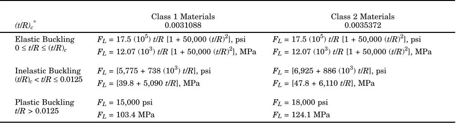
3.4 Column, Strut, and Shell Stability Formulas... 16
3.5 Shell Girder, Intermediate Stiffeners, and Compression 3.7 Cylindrical Shell Plates ... 26
3.8 Foundation Bolts ... 27
3.9 Corrosion Allowance ... 29
3.10 Minimum Thickness... 29
3.11 Joints ... 29
3.12 Weld Design Values ... 30
3.13 Reinforcement Around Openings .... 31
3.14 Equivalent Metric Equations ... 32
4 Sizing and Design of Elevated Tanks 4.1 Standard Capacities ... 33
4.2 Heights for Elevated Tanks ... 33
4.3 Standard Head Range... 33
4.4 Columns and Struts ... 33
4.5 Tension Members Carrying Wind and Seismic Loads ... 34
4.6 Pinholes... 34
4.7 Horizontal Girders ... 34
4.8 Tank Plates ... 35
4.9 Steel Riser... 36
4.10 Tank Stability Against Overturning ... 36
4.11 Pedestal Tank Slenderness... 36
4.12 Pedestal Supports... 36
4.13 Eccentric Load ... 36
4.14 Lateral Load Distribution... 36
4.15 High Slender Tanks ... 37
5 Accessories for Elevated Tanks 5.1 Steel Riser... 37
5.2 Pipe Connection... 37
5.3 Overflow ... 38
5.4 Ladders... 38
5.5 Safety Devices... 39
5.6 Roof Openings... 39
Standpipes and Reservoirs
6.1 Standard Capacities ... 40
6.2 Shell Heights for Standpipes... 40
6.3 Diameters for Reservoirs ... 40
7 Accessories for Supported Standpipes and Reservoirs 7.1 Shell Manholes ... 41
7.2 Pipe Connections ... 41
7.3 Overflow ... 41
7.4 Ladders... 42
7.5 Safety Devices... 42
7.6 Roof Openings ... 42
7.7 Vent... 43
7.8 Additional Accessories and Exceptions... 43
8 Welding 8.1 Definitions and Symbols ... 43
8.2 Welding Inspector ... 43
8.3 Qualification of Welding Procedures, Welders, and Welding Operators .. 44
8.4 Weld Joint Records ... 45
8.5 Butt Joints ... 45
8.6 Lap Joints ... 45
8.7 Flat Tank Bottoms Resting Directly on Grade or Foundation ... 45
8.8 Shell-to-Bottom Joint ... 46
8.9 Roof Plates ... 46
8.10 Maximum Thickness of Material to Be Welded ... 46
8.11 Minimum Laps for Welded Lap Joints... 47
8.12 Minimum Size of Fillet and Seal Welds... 47
8.13 Minimum Length of Welds ... 47
8.14 Intermittent Welding... 47
8.15 Safety in Welding and Cutting ... 48
8.16 Safe Usage of Cutting and Welding Processes... 48
9 Shop Fabrication 9.1 Workmanship ... 48
9.2 Laying Out ... 48
9.3 Straightening ... 48
9.6 Double-Curved Plates ... 48
9.7 Milling of Columns ... 49
9.8 Shop Assembly ... 49
9.9 Shipping ... 49
10 Erection 10.1 General ... 49
10.2 Welds ... 49
10.3 Preparation of Surfaces to Be Welded ... 50
10.4 Preheating and Interpass Temperature ... 51
10.5 Low-Hydrogen Electrodes ... 51
10.6 Tack Welds ... 51
10.7 Tank Assembly... 51
10.8 Matching Plates... 53
10.9 Grouting of Column, Riser, and Single-Pedestal Bases for Elevated Tanks... 53
10.10 Cleanup ... 53
11 Inspection and Testing 11.1 Mill or Shop Inspection... 53
11.2 Field Inspection ... 54
11.3 Welders’ Credentials... 54
11.4 Inspection of Welded Joints ... 55
11.5 Number and Location of Radiographs or Sectional Segments for Butt Weld Joints in Tank Shells, Load-Bearing Risers, and Single-Pedestal Columns ... 56
11.6 Procedures for Inspection of Welded-Shell Butt Joints— Radiographic Testing ... 58
11.7 Procedure for Inspection of Groove Welds in Tension Member Bracing by Ultrasonic Inspection... 59
11.8 Procedure for Inspection of Welded Joints by Removal of Sectional Segments ... 60
11.9 Inspection by Air Carbon Arc Gouging... 61
11.10 Methods for Closing of Openings .... 61
11.11 Repair of Defective Welds ... 63
11.12 Testing ... 63
12.1 General Requirements ... 64
12.2 Soil-Bearing Value ... 64
12.3 Safety Factors ... 65
12.4 Foundations for Braced Elevated Tanks... 65
12.5 Foundations for Single-Pedestal Tanks... 66
12.6 Foundations for Flat-Bottom Tanks... 66
12.7 Detail Design of Foundations ... 68
12.8 Concrete Design, Materials, and Construction ... 70
12.9 Backfill ... 70
13 Seismic Design of Water Storage Tanks 13.1 General ... 70
13.2 Seismic Design Categories ... 70
13.3 Seismic Design Loads... 71
13.4 Local Seismic Data ... 85
13.5 Piping Connections for Flat-Bottom Tanks... 86
13.6 Foundation Design ... 86
13.7 Specification Sheets for Seismic Data and Examples... 87
13.8 Equivalent Metric Equations... 99
14 Alternative Design Basis for Standpipes and Reservoirs 14.1 Alternative Design Basis ... 100
14.2 Materials ... 103
14.3 General Design ... 110
14.4 Inspection ... 112
14.5 Certification of Compliance ... 114
15 Structurally Supported Aluminum Dome Roofs 15.1 General ... 115
15.2 Definition... 115
15.3 Design Requirements ... 115
15.4 Materials ... 115
15.5 Allowable Stresses ... 116
15.6 Design... 117
15.7 Roof Attachment Details ... 118
15.8 Physical Characteristics... 118
15.9 Testing and Sealing ... 118
A Bibliography... 121
Figures 1 Mean Tank Height ... 11
2 Diagram for Checking Overturning of Pedestal-Type Elevated Tanks (Wind or Seismic Events) ... 67
3 Extreme Frost Penetration—in Inches (Based on State Average) .... 69
4 Recommended Depth of Cover (in Feet Above Top of Pipe) ... 69
5 Relative Seismic Resistance of Typical Unanchored Flat-Bottom Tanks ... 72
6 Diagram for Checking Overturning of Cross-Braced Elevated Tanks (Seismic) ... 75
7 Seismic Zone Map of the United States and Puerto Rico for Seismic Design of Water Storage Tanks .... 75
8 Curve for Obtaining Factor Kp for the Ratio D/H... 77
9 Curves for Obtaining Factors W1/WT and W2/WT for the Ratio D/H... 79
10 Curves for Obtaining Factors X1/H and X2/H for the Ratio D/H... 79
11 Increase in Axial-Compressive Buckling-Stress Coefficient of Cylinders Due to Internal Pressure (for Use With Unanchored Tanks Only) ... 85
12 Bottom Piping Connection of an Unanchored Flat-Bottom Tank ... 86
13 Certification to Purchaser of Compliance With Inspection Requirements Under Sec. 14 ... 102
14 Recommended Nameplate ... 104
1 Thickness Limitations and Special
Requirements ... 7
2 Wind Drag Coefficient Cd... 10
3 Material Classes ... 12
4 Unit Stresses—Tension ... 13
5 Unit Stresses—Compression ... 13
6 Unit Stresses—Primary Bending .... 14
7 Unit Stresses—Shearing... 14
8 Unit Stresses—Bearing... 15
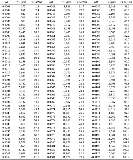
9 Values of FL, (t/R)c for Class 1 and Class 2 Materials... 18
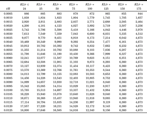
10 Allowable Local Compressive Stress FL for Class 1 Materials L/r ≤ 24 ... 19
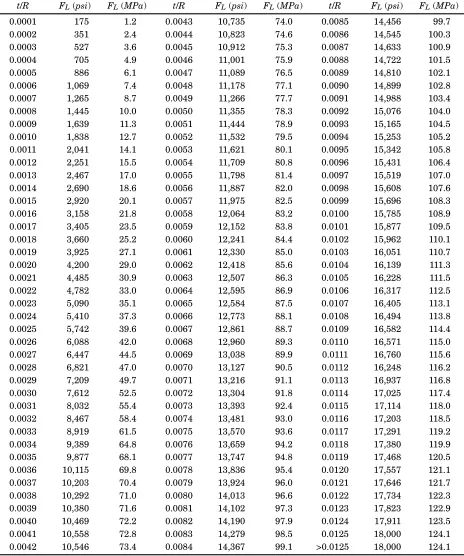
11 Allowable Local Compressive Stress FL for Class 2 Materials L/r ≤ 24 ... 20
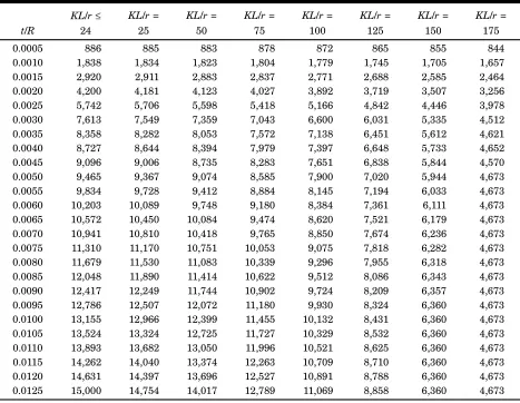
12 Allowable Compressive Stress for Combined Effects of Local Buckling and Slenderness for Class 1 Materials (psi)... 21
13 Allowable Compressive Stress for Combined Effects of Local Buckling and Slenderness for Class 2 Materials (psi)... 22
14 Weld Design Values—Tank Plate Joints... 27
15 Minimum Thickness of Cylindrical Shell Plates in Contact With Water... 30
Tanks... 34
17 Standard Capacities for Standpipes and Reservoirs... 40
18 Minimum Size of Fillet Weld—Shell-to-Bottom Joint... 46
19 Minimum Diameter for Plates Not Rolled ... 49
20 Maximum Thickness of Reinforcement for Butt Joints ... 50
21 Roundness—Cylindrical Shells ... 52
22 Maximum Allowable Offset of Aligned Butt Joints... 53
23 Maximum Height of Weld Reinforcement of Weld for Butt Joints Above Plate Surface... 58
24 Zone Coefficient Z... 74
25 Force Reduction Coefficient Rw for Type of Tank ... 74
26 Use Factor I... 74
27 Site Amplification Factor S... 74
28 Category 1 Material Requirements for Shell Plates in Contact With Water to Be Used for Design Metal Temperature Tabulated .... 105
29 Category 2 Materials... 106
30 Category 3 Materials... 106
31 Maximum Design Tensile Stresses in Shell Plates in Contact With Water... 111
32 Minimum Thickness of Bottom Annular Rings ... 112
This foreword is for information only and is not a part of AWWA D100.
I. Introduction
I.A. Background. In 1931, American Water Works Association (AWWA)
Sub-committee 7H, whose members were L.R. Howson, H.C. Boardman, and James O. Jackson, prepared “Standard Specifications for Riveted Steel Elevated Tanks and Standpipes.” The specifications were published in the November 1935 edition of
Journal AWWA. In 1940, the scope of the standard specifications was expanded to include welded construction. The American Welding Society (AWS) cooperated in the revision and became a joint sponsor of the standard. Since its original publication, the standard has gained wide acceptance in the United States and abroad.
I.B. History. In 1965, appendix C was added to provide for the alternative use
of higher-strength steels for standpipes and reservoirs. Other changes included the addition of specifications for the use of steel pipe as tubular columns, and a wind-pressure formula for winds in excess of 100 mph. The requirements for loads on balconies and ladders and unit stresses for combinations of wind, seismic, and other loads were clarified. The rules for the minimum thickness of shell plates for stand-pipes and reservoirs were revised to apply only to cylindrical shells and not to knuckles or toroidal or elliptical roof plates containing water. The swivel ladder for standpipes and reservoirs, which was found to be impractical, was eliminated, and a fixed ladder was specified. The rules for welding and for weld qualification were rewritten completely. The qualification procedure of the American Society of Mechanical Engineers (ASME) Boiler and Pressure Vessel Code, Sec. IX, was adopted, and the sizes of fillet welds in the shell-to-bottom joints of standpipes and reservoirs were revised, as were the sections on sand cushions and grouting for standpipe and reservoir bottoms. Rules for inspection of welds were rewritten completely. An isothermal map showing the lowest one-day mean temperature in various parts of the continental United States and parts of Canada was included. Concrete foundation design was brought into conformity with American Concrete Institute (ACI) Standard No. 318, Building Code Requirements for Reinforced Concrete.
In 1973, the use of rivets for joints in tank shells was eliminated. Specifications for tank steels were revised to include low-alloy steels. The design of foundations for elevated tanks and standpipes was changed extensively, making foundation design a part of the mandatory specification. Procedures for soil investigation were recommended.
stiffeners were classified into three categories in appendix C, and the requirements for impact testing were expanded.
In 1984, revisions included new sections pertaining to single-pedestal tanks incorporating design rules for this type of tank. New design rules were included for columns of elevated tanks having eccentric work point connections. A section covering the design considerations for struts was added. For combined stresses, the unit
stresses for wind and seismic forces were increased from 25 percent to 331⁄3 percent.
Shell plates thicker than 2 in. (51 mm) conforming to American Society for Testing and Materials (ASTM) A36, Specification for Structural Steel, were allowed to be used provided their usage was in compliance with certain stipulated conditions and requirements. Ground-supported tanks not greater than 50 ft (15.2 m) in diameter
were allowed to have a minimum shell thickness of 3⁄16 in. (7.9 mm). A minimum
size and maximum spacing were added for foundation bolts. The previous appendix A on seismic design was incorporated into the standard as Sec. 13. In addition, a new section was added to Sec. 13 to permit scaling down to specific site response spectra when local seismic data are available.
Appendix C, Alternative Rules and Design Stresses for the Use of Steel Plates and Shapes With Suitable Toughness and Ductibility for Use in Welded Standpipes and Reservoirs at Specified Minimum Ambient Temperatures, was made a part of the standard while retaining its title designation as appendix C.
For appendix C tanks with a height to diameter (H/D) ratio of 0.50 or less, the
shell design was allowed to be by the Variable Design Point Method in compliance with API 650. Also, for appendix C tanks, inspection of certain members is not required when the material has a tensile strength less than 75,000 psi (517.1 MPa).
The major revisions in this edition are summarized in Sec. IV of this foreword.
I.C. Acceptance. In May 1985, the US Environmental Protection Agency
(USEPA) entered into a cooperative agreement with a consortium led by NSF Inter-national (NSF) to develop voluntary third-party consensus standards and a certifica-tion program for all direct and indirect drinking water additives. Other members of the original consortium included the American Water Works Association Research Foundation (AWWARF) and the Conference of State Health and Environmental Managers (COSHEM). The American Water Works Association (AWWA) and the Asso-ciation of State Drinking Water Administrators (ASDWA) joined later.
In the United States, authority to regulate products for use in, or in contact
with, drinking water rests with individual states.* Local agencies may choose to
impose requirements more stringent than those required by the state. To evaluate the health effects of products and drinking water additives from such products, state and local agencies may use various references, including
1. An advisory program formerly administered by USEPA, Office of Drinking Water, discontinued on Apr. 7, 1990.
Drinking Water Treatment Chemicals—Health Effects, and ANSI/NSF 61, Drinking Water System Components—Health Effects.
4. Other references, including AWWA standards, Food Chemicals Codex,
Water Chemicals Codex,‡ and other standards considered appropriate by the state or local agency.
Various certification organizations may be involved in certifying products in accordance with ANSI/NSF 61. Individual states or local agencies have authority to accept or accredit certification organizations within their jurisdiction. Accreditation of certification organizations may vary from jurisdiction to jurisdiction.
Appendix A, “Toxicology Review and Evaluation Procedures,” to ANSI/NSF 61 does not stipulate a maximum allowable level (MAL) of a contaminant for sub-stances not regulated by a USEPA final maximum contaminant level (MCL). The MALs of an unspecified list of “unregulated contaminants” are based on toxicity testing guidelines (noncarcinogens) and risk characterization methodology (carcino-gens). Use of Appendix A procedures may not always be identical, depending on the certifier.
AWWA D100-96 does not address additives requirements. Thus, users of this standard should consult the appropriate state or local agency having jurisdiction in order to
1. Determine additives requirements including applicable standards.
2. Determine the status of certifications by all parties offering to certify products for contact with, or treatment of, drinking water.
3. Determine current information on product certification.
II. Special Issues. This standard has no applicable information for this section.
III. Use of This Standard. AWWA has no responsibility for the suitability or compatibility of the provisions of this standard to any intended application by any user. Accordingly, each user of this standard is responsible for determining that the standard’s provisions are suitable for and compatible with that user’s intended application.
This standard is based on the accumulated knowledge and experience of
pur-chasers and manufacturers of welded steel tanks.§
Many tanks built in compliance with the first edition of this standard are more than 50 years old and are still in service. Properly operated and maintained welded steel water tanks can have an almost unlimited service life.
III.A. Purchaser Options and Alternatives. If tanks are purchased in accordance
with this standard, the purchaser is required to specify certain basic requirements. The purchaser may desire to modify, delete, or amplify sections of this standard to suit special conditions. It is strongly recommended that such modifications, deletions, or amplifications be made by supplementing this standard. This standard is not intended to cover storage tanks that are to be erected in areas subject to regulations
*American National Standards Institute, 11 W. 42nd St., New York, NY 10036.
†NSF International, 3475 Plymouth Rd., Ann Arbor, MI 48106.
‡Both publications available from National Academy of Sciences, 2102 Constitution Ave.
regulations supersede the requirements of this standard. Where local, municipal, county, or state government requirements exist, such requirements are to govern and this standard should be interpreted to supplement them. It is the purchaser’s responsibility to supplement or modify this standard for compliance with these local requirements. In addition, the purchaser is to provide clarification of the governing codes where they do not clearly refer to tanks, but where the purchaser intends such stipulations to apply to the tank under contract. As an example, if a governing code
stipulates a building roof snow load of 40 lb/ft2 (195 kg/m2) and it is intended that
the tank roof be designed for this load, the purchaser is to include this as a clarification. The details of design and construction covered by this standard are minimum requirements. At a minimum, it is important that all of the design conditions in this
standard be met.* A tank cannot be represented as an AWWA D100 tank if it does
not meet the minimum requirements of this standard.
The foundations of tanks are one of the more important aspects of tank design; detailed requirements are covered in Sec. 12. This standard requires the constructor to be responsible for the design and construction of the tank foundations. The purchaser must obtain an adequate soil investigation at the site, including recommendation of the type of foundation to be used, the depth of foundation required, and the design soil-bearing pressure. This information, as well as specifications for an adequate soil investigation, should be established by a qualified geotechnical engineer.
A drainage inlet structure or suitable erosion protection should be provided to receive discharge from the tank overflow. The overflow should not be connected directly to a sewer or a storm drain without an air break.
Annual inspection and maintenance of the exposed side of the tank shell-to-bottom connection for a standpipe or reservoir is important if maximum tank life is to be attained. In particular, accumulations of dirt and weeds, which may trap moisture and accelerate corrosion, should be removed. Inspection of the interior and exterior of the entire tank with corrective maintenance at three- to five-year intervals is recommended.
This standard assumes that the purchaser (owner) provides sufficient water replacement and circulation to prevent freezing in the tank and riser pipe. Where low usage may result in the possibility of freezing, the owner should waste water or provide heat to prevent freezing. The purchaser is referred to National Fire Protection Association (NFPA) document NFPA 22, Water Tanks for Private Fire Protection, for heater sizing. Purchasers are cautioned against allowing ice buildup for insulation, which may break loose and damage the tank. Where reference to ice damage is discussed in the standard, it is in anticipation of improper operation rather than approval of an icing condition.
disinfecting is to be done.
The following recommendations are believed to represent good practice, but they are not requirements of ANSI/AWWA D100. When a welded steel tank is to be purchased under this standard, the purchaser should provide the following:
1. The site on which the tank is to be built, including sufficient space to permit the structure to be erected by customary methods.
2. Water at the proper pressure for testing, as required, and facilities for disposal of wastewater after testing.
3. A suitable right-of-way from the nearest public road to the erection site. 4. Materials furnished by the purchaser to be used by the constructor for construction of the tank.
The constructor should furnish the following items:
1. Foundation and tank design, drawings, and specifications.
2. All labor and materials, except materials furnished by the purchaser, nec-essary to complete the structure including the foundations and accessories required by this standard.
3. Any additional work, separately specified by the purchaser, such as soil investigations, painting, disinfection, or accessories.
Variations in the responsibilities of both the purchaser and the constructor, as previously outlined, may be made by contractual agreement. The purchaser and the bidder should each furnish the information identified in the following listings.
III.A.1 Information to Be Furnished by Purchaser for an Elevated Tank. The following information should be furnished by the purchaser when taking bids for an elevated tank:
1. Capacity.
2. Bottom capacity level (BCL) and top capacity level (TCL) above top of column foundations.
3. Type of roof, roof pitch, and projection at eaves (unless the purchaser desires to leave to the constructor the selection of appropriate dimensions).
4. Head range, if specific range is required. 5. Diameter and type of riser.
6. Location of site.
7. Desired time for completion.
8. Name of, and distance to, nearest town.
9. Name of, and distance to, nearest railroad siding.
10. Type of road available for access to the site and whether it is public or private.
11. Availability of electric power; who furnishes it; at what fee, if any; what voltage; whether direct or alternating current; and, if alternating current, what cycle and phase.
12. Availability of compressed air; pressure, volume, and fee, if any.
13. Whether details of all welded joints referenced on the constructor’s drawings are to be submitted for approval (Sec. 1.4).
14. Whether copper-bearing steel is required (Sec. 2.2.6).
load requirements (Sec. 3.1.4).
18. Whether seismic design is required, and which seismic zone (1, 2A, 2B, 3, or 4) is to be used (Sec. 3.1.5).
19. Corrosion allowance, if any, to be added to parts that will be in contact with water and to parts that will not be in contact with water (Sec. 3.9).
20. Whether a balcony is required for inspection and painting when a horizontal girder is not required by the tank design (Sec. 4.7).
21. Whether increased wind loads are to be considered for high, slender tanks (Sec. 4.11).
22. Location of manholes, ladders, and any additional accessories required (Sec. 5).
23. Number and location of pipe connections, and type and size of pipe to be
accommodated. NOTE: Connections to the piping furnished by the tank constructor
are to be made by the purchaser (Sec. 5.2).
24. Whether a removable silt stop is required (Sec. 5.2.1).
25. Overflow type, whether stub or to ground or (if applicable) to extend below balcony; size of pipe; pumping and discharge rates (Sec. 5.3).
26. Whether the roof ladder for providing access to roof hatches and vents is to be omitted (Sec. 5.4.3).
27. Whether safety cages, rest platforms, roof-ladder handrails, or other safety
devices are required and on which ladders (Sec. 5.5). NOTE: Purchaser is to specify
beginning location of outside tank ladder if other than at a level of 8 ft (2.4 m) above the level of the tank bottom.
28. Whether a special pressure-vacuum screened vent, or a pressure-vacuum relief mechanism is required for the tank vent (Sec. 5.7.2).
29. Specifications for any additional accessories required (Sec. 5.8).
30. For butt-joint welds subject to secondary stress, whether complete joint penetration is to be provided at joints in base metals of thicknesses greater than
3⁄8 in. (9.5 mm) (Sec. 8.5.2).
31. Whether mill or shop inspection is required and whether mill test reports are required (Sec. 11.1).
32. Whether a written report is required certifying that the work was inspected as set forth in Sec. 11.2.1.
33. Whether radiographic film or test segments, or both, are to become the property of the purchaser (Sec. 11.2.1.1).
34. Type of inspection to be performed on complete joint penetration welded-shell butt joints (Sec. 11.4.1.1).
35. Whether steel is to be blast cleaned, pickled, or otherwise cleaned of mill scale. Kinds of paint or protective coatings and number of coats for inside and out-side surfaces, and whether materials are to be furnished and applied by the tank constructor (Sec. 11.13.1). Also, whether the tank is to be painted before or after water testing of the tank.
36. Whether seal welding is required and, if so, where it is required (Sec. 8.12.2).
37. Soil investigation including foundation design criteria, type of foundation
required (Sec. 12.7.3). The purchaser shall make appropriate provisions for establishing criteria for compensation adjustment due to piling length changes resulting from varying subsurface conditions.
39. Whether the effect of buoyancy is to be considered in the foundation design (Sec. 12.7.4).
40. Whether all requirements of ACI 301, Specifications for Structural Concrete for Buildings, are applicable to the concrete work (Sec. 12.8).
41. Vertical distance from finished ground level to the crown of inlet and out-let pipe (earth cover) at riser pier (Sec. 12.9.2).
42. Completion of the Specification Sheet for Seismic Data when seismic design is required (Sec. 13.1.2).
43. Whether vertical acceleration is to be considered for cross-braced or pedestal-type elevated tanks (Sec. 13.3.1.3(4) and Sec. 13.3.2.3).
44. Whether local seismic data are available and whether they are to be used in place of acceleration and spectral velocity values (Sec. 13.4). Also, the reduction factor to be used if scaled-down response spectra are used for ductile-mode stresses (Sec. 13.4.1).
45. Whether third-party inspection will be used by the purchaser and for which items.
III.A.2 Information to Be Furnished by Purchaser for a Standpipe or Reservoir (Ground-Supported Tanks). The following information should be furnished by the purchaser when taking bids for a ground-supported tank:
1. If a standpipe, capacity and top capacity level. 2. If a reservoir, capacity and diameter.
3. Type of roof, roof pitch, and projection at eaves (unless the purchaser allows the constructor to select the appropriate dimensions).
4. Location of site.
5. Desired time for completion.
6. Name of, and distance to, nearest town.
7. Name of, and distance to, nearest railroad siding.
8. Type of road available for access to the site and whether it is public or private.
9. Availability of electric power; who furnishes it; at what fee, if any; what voltage; whether it is a direct or an alternating current; and, if it is an alternating current, what cycle and phase.
10. Availability of compressed air; pressure, volume, and fee, if any.
11. The bottom capacity level of the tank, when empty, if it differs from the level when the tank would be emptied through the specified discharge fittings (Sec. 1.2.1.1).
12. Whether details of all welded joints referenced on the constructor’s drawings are to be submitted for approval (Sec. 1.4).
13. Whether copper-bearing steel is required (Sec. 2.2.6).
14. Type of pipe and fittings for fluid conductors (Sec. 2.2.12). Also, type of pipe joint if different from that permitted in Sec. 2.2.12.
or 4) is to be used (Sec. 3.1.5).
18. Type, thickness, and kind of roof support, if required (Sec. 3.6).
19. Corrosion allowance, if any, to be added to parts that will be in contact with water and to parts that will not be in contact with water (Sec. 3.9). This also applies when a tank is to be furnished to comply with Sec. 14.
20. Design, details, and installation of flush-type cleanouts, if required (Sec. 3.13.2.5).
21. Location of manholes, ladders, and additional accessories required (Sec. 7). 22. Number and location of pipe connections, and type and size of pipe to be
accommodated. NOTE: Connections to the piping furnished by the tank constructor
are to be made by the purchaser (Sec. 7.2).
23. Whether a removable silt stop is required (Sec. 7.2.1).
24. Overflow type, whether stub or to ground; size of pipe; pumping and discharge rates (Sec. 7.3).
25. Whether the roof ladder for providing access to roof hatches and vents is to be omitted (Sec. 7.4.3).
26. Whether safety cages, rest platforms, roof-ladder handrails, or other safety
devices are required and on which ladders (Sec. 7.5). NOTE: Purchaser is to specify
beginning location of outside tank ladder if other than at a level of 8 ft (2.5 m) above the level of the tank bottom.
27. Whether a special pressure-vacuum screened vent or a pressure-vacuum relief mechanism is required for the tank vent (Sec. 7.7).
28. Specifications for any additional accessories required (Sec. 7.8).
29. Whether a certified welding inspector is required for Sec. 14 tanks (Sec. 8.2).
30. For butt-joint welds subject to secondary stress, whether complete joint
penetration is to be provided at joints in materials of thicknesses greater than 3⁄8 in.
(9.5 mm) (Sec. 8.5.2).
31. Whether mill or shop inspection is required and whether mill test reports are required (Sec. 11.1).
32. Whether a written report is required certifying that the work was inspected as set forth in Sec. 11.2.1.
33. Whether radiographic film or test segments, or both, are to become the property of the purchaser (Sec. 11.2.1.1).
34. Type of inspection to be performed on complete joint penetration welded-shell butt joints (Sec. 11.4.1.1).
35. Whether steel is to be blast cleaned, pickled, or otherwise cleaned of mill scale. Kinds of paint or protective coatings and number of coats required for inside and outside surfaces except underside of bottom, and whether materials are to be furnished and applied by tank constructor (Sec. 11.13.1).
36. Whether seal welding is required and, if so, where it is required.
37. Soil investigation including foundation design criteria, type of foundation
(Sec. 12.6), depth of foundation below existing grade, S factor for seismic areas, and
design soil-bearing pressure, including factor of safety. NOTE: The top of the foundation
(Sec. 12.8).
40. Vertical distance from finished ground level to the crown of inlet and out-let pipes (earth cover) at tank foundation (Sec. 12.9.2).
41. Completion of the Specification Sheet for Seismic Data when seismic design is required (Sec. 13.1.2).
42. Whether vertical acceleration is to be considered (Sec. 13.3.3.7.1). 43. Amount of freeboard for sloshing wave (Sec. 13.3.3.7.2).
44. Whether seismic design of roof framing and columns is required (Sec. 13.3.3.7.3) and amount of live loads and vertical acceleration to be used.
45. Whether local seismic data are available and whether they are to be used in place of acceleration and spectral velocity values (Sec. 13.4). Also, the reduction factor to be used if scaled-down response spectra are used (Sec. 13.4.1).
46. For tanks designed under Sec. 14, design metal temperature (Sec. 14.2.4). 47. Whether third-party inspection will be used by the purchaser and for which items.
III.B. Information to Be Furnished by Bidder.
III.B.1 Information to Be Furnished by Bidder for an Elevated Tank. The follow-ing information should be furnished by the bidder for an elevated tank:
1. A drawing showing the dimensions of the tank and tower including the tank diameter, the height to bottom and top capacity levels (BCL and TCL), sizes of principal members, and thickness of plates in all parts of the tank and tower. Also, the maximum wind or seismic gross moment and shear on the foundation system should be identified.
2. The number, names, and sizes of all accessories. 3. Painting information, if included.
III.B.2 Information to Be Furnished by Bidder for a Standpipe or Reservoir (Ground-Supported Tanks). The following information shall be furnished by the bid-der for a ground-supported tank:
1. A drawing showing the dimensions of the standpipe or reservoir including the diameter, top capacity level (TCL), shell height including plate thickness, type and thickness of the roof, thickness of the bottom plates, and thickness of the bot-tom annular ring. Also, the maximum wind or seismic gross moment and shear on the foundation system shall be identified.
2. The number, names, and sizes of all accessories. 3. Painting information, if included.
III.C. Modification to Standard. Any modification of the provisions, definitions,
or terminology in this standard must be provided in the purchaser’s specifications.
IV. Major Revisions. This edition of the standard includes numerous correc-tions, updates, and new material to clarify some of the existing requirements.
Section 2 includes new data on the types and thicknesses of materials and their uses in tank construction. Section 3 has been extensively revised in the area of design load definitions, and the reference tables, figures, and equations used in the design of welded steel tanks. Minimum plate thicknesses, roofs, anchor bolts, and flush-type cleanouts have been defined. The buckling requirements of conical and double-curved shells have been clarified.
welding inspectors, has been expanded to improve quality control during construction. Critical joint details, materials, and sizes of welds are also clarified.
Section 10 has been revised to better define temperature limits for welding and limits of weld “reinforcement.”
Section 11 includes extensive changes concerning the inspection of welded joints. Tank shell, tubular support columns, tension member bracing, and large-diameter riser joints are discussed, and radiograph requirements have been revised. The pene-trometer techniques and details have also been revised to conform to ASME criteria.
Section 12 has minor changes, and Sec. 12.6 concerning foundations for flat-bottom tanks has been revised.
Section 13 covering seismic design has extensive revisions updating the methods to calculate forces and stresses. A new seismic map of the United States is included along with new and revised equations for calculating such things as hydrodynamic seismic hoop tensile stresses, and sloshing wave height to determine minimum freeboard.
Appendix C of the previous edition has been incorporated into the standard as Sec. 14. Reference standards have been moved to Sec. 1.
Electrode criteria and requirements for permanent and temporary attachment criteria have been revised. The type of inspection and number of weld joint inspections have also been updated for better quality control.
A new Sec. 15, entitled Structurally Supported Aluminum Dome Roofs, has been added. It provides the purchaser with the flexibility to choose an alternative roof system.
The entire standard was reviewed carefully, and minor changes were made in many of the sections to improve understanding and readability. Tabulated values and equations throughout this standard have been revised to include English and SI units of measurement. In the event of a discrepancy between the values, the English unit values shall govern.
IV.A. Comment Regarding Sec. 14. Advancements in production techniques for
higher-strength steels, coupled with increasing production volumes, have resulted in a reduction in the cost differential between high-strength and structural-grade steels. Consequently, the trend in the steel tank industry has been increasing application of the alternative Sec. 14 design procedure for welded standpipes and reservoirs, espe-cially in the case of larger structures. Although appendix C was made a part of the ANSI/AWWA D100 (AWS D5.2) standard for the 1984 revision while retaining its position as an appendix, it has now been placed in the standard as Sec. 14 to comply with AWWA’s standard procedures.
ANSI/AWWA D100-96
(Revision of AWWA D100-84)
AWWA STANDARD FOR
WELDED STEEL TANKS FOR
WATER STORAGE
WELDED STEEL TANKS FOR WATER STORAGE
SECTION 1: GENERAL
Sec. 1.1 Scope
The purpose of this standard is to provide guidance to facilitate the design, manufacture, and procurement of welded steel tanks for the storage of water.
1.1.1 Tank roofs. All tanks storing potable water shall have roofs. Tanks storing
nonpotable water may be constructed without roofs.
1.1.2 Items not covered. This standard does not cover all details of design and
construction because of the large variety of sizes and shapes of tanks. Where details for any specific design are not given, it is intended that the constructor, subject to the approval of the purchaser, shall provide details that are designed and constructed to be adequate and as safe as those that would otherwise be provided under this standard.
This standard does not cover concrete-steel composite tank construction.*
Sec. 1.2 Definitions
The following definitions shall apply in this standard:
1.2.1 Capacity: The net volume, in gallons (litres), that may be removed from
a tank filled to top capacity level (TCL) and emptied to the bottom capacity level (BCL).
1. In a ground-supported tank (reservoir or standpipe), the BCL shall be the water level in the tank shell when the tank is emptied through the specified discharge fittings, unless otherwise specified by the purchaser.
2. In an elevated tank, the elevation of the BCL or TCL shall be specified by the purchaser.
3. The TCL is the elevation to the lip of the overflow.
4. The BCL is the elevation above which the required capacity is provided. 5. The head range is the vertical distance between the BCL and the TCL.
1.2.2 Constructor: The party that furnishes the work and materials for
place-ment and installation.
1.2.3 Elevated tank: A container or storage tank supported on a tower.
1.2.4 Manufacturer: The party that manufactures, fabricates, or produces
materials or products.
1.2.5 Purchaser: The person, company, or organization that purchases any
materials or work to be performed.
1.2.6 Reservoir: A ground-supported, flat-bottom cylindrical tank having a shell
height equal to or smaller than its diameter.
1.2.7 Standpipe: A ground-supported, flat-bottom cylindrical tank having a shell
height greater than its diameter.
1.2.8 Supplier: The party that supplies materials or services. A supplier may
or may not be the manufacturer.
1.2.9 Tank: An elevated tank, a standpipe, or a reservoir.
Sec. 1.3 Guarantee
The constructor shall guarantee the structure against any defective materials or workmanship, including paint and painting if furnished by the constructor, for a period of one year from the date of completion. If any materials or workmanship prove to be defective within one year, they shall be replaced or repaired by the constructor.
Sec. 1.4 Drawings to Be Furnished
After award of the contract, the constructor shall submit foundation and tank construction drawings which shall bear the certification of a professional engi-neer licensed in the jurisdiction where the tank is to be erected. Where foundation and tank design are performed by separate parties, each party shall provide draw-ings bearing the certification of a licensed professional engineer. Construct-only con-tracts shall bear the professional engineering certification of the original designer or the purchaser’s engineer.
Drawings shall be submitted to the purchaser for approval before proceeding with fabrication. If waived by the purchaser, fabrication may proceed prior to approval of the drawings. If required by the purchaser, details of all welded joints shall be submitted for approval. Standard weld symbols as listed in ANSI/AWS 2.4 shall be used, unless joint details are shown.
Sec. 1.5 References
AA SAS*—Specifications for Aluminum Structures.
AAMA† 605.1—Voluntary Specification for High-Performance Organic Coatings
on Architectural Extrusions.
ACI‡ 301—Specifications for Structural Concrete for Buildings.
ACI 318—Building Code Requirements for Reinforced Concrete.
ACI 349—Code Requirements for Nuclear Safety Related Concrete Structures. Appendix B.
AISC§ (ASD)—Manual of Steel Construction (Allowable Stress Design) and
Specification for Structural Steel Buildings—Allowable Stress Design and Plastic Design.
ANSI** B16.5—Steel Pipe Flanges and Flanged Fittings.
ANSI Z49.1—Safety in Welding and Cutting and Allied Processes.
ANSI/AWS†† A1.1—Metric Practice Guide for the Welding Industry.
ANSI/AWS A2.4—Standard Symbols for Welding, Brazing and Nondestructive Examination.
ANSI/AWS A3.0—Standard Welding Terms and Definitions Including Terms for Brazing, Soldering Thermal Spraying, and Thermal Cutting.
ANSI/AWS A5.1—Specification for Carbon Steel Electrodes for Shielded Metal Arc Welding.
ANSI/AWS A5.5—Specification for Low Alloy Steel Electrodes for Shielded Metal Arc Welding.
ANSI/AWS B2.1—Standard Welding Procedure Specification (WPS). ANSI/AWS D1.1—Structural Welding Code Steel.
ANSI/AWS D1.2—Structural Welding Code Aluminum.
ANSI/AWWA C652—Standard for Disinfection of Water-Storage Facilities. ANSI/AWWA D103—Standard for Factory-Coated Bolted Steel Tanks for Water Storage.
API‡‡ SPEC 5L—Specification for Line Pipe.
API STD 650—Welded Steel Tanks for Oil Storage.
ASME SEC V—Boiler and Pressure Vessel Code, Nondestructive Examination.
ASME§§ SEC VIII D1—Boiler and Pressure Vessel Code, Pressure Vessels,
Appendix IV, Rounded Indications Charts, Acceptance Standard for Radiographically Determined Rounded Indications in Welds.
ASME SEC IX—Boiler and Pressure Vessel Code, Qualification Standard for Welding and Brazing Procedures, Welders, Brazers, and Welding and Brazing Operators.
*Aluminum Association, 818 Connecticut Ave., Washington, DC 20006.
†The Architectural Aluminum Manufacturers Association, 900 19th St. N.W., Washington,
DC 20006.
‡American Concrete Institute, Box 19150, Detroit, MI 48219.
§American Institute of Steel Construction, Wrigley Bldg., 8th Floor, 400 N. Michigan Ave.,
Chicago, IL 60611.
**American National Standards Institute, 11 W. 42nd St., New York, NY 10036.
ASNT* SNT-TC-1A—Recommended Practice for Personnel Qualification and Certification in Nondestructive Testing.
ASTM† A6—Standard Specification for General Requirements for Rolled
Struc-tural Steel Bars, Plates, and Shapes, Sheet Piling.
ASTM A20—Standard Specification for General Requirements for Steel Plates for Pressure Vessels.
ASTM A27—Standard Specification for Steel Castings, Carbon, for General Application.
ASTM A36—Standard Specification for Carbon Structural Steel.
ASTM A53—Standard Specification for Pipe, Steel, Black and Hot-Dipped, Zinc-Coated, Welded and Seamless.
ASTM A105—Standard Specification for Carbon Steel Forgings for Piping Components.
ASTM A106—Standard Specification for Seamless Carbon Steel Pipe for High-Temperature Service.
ASTM A108—Standard Specification for Steel Bars, Carbon, Cold-Finished, Standard Quality.
ASTM A131—Standard Specification for Structural Steel for Ships.
ASTM A139—Standard Specification for Electric-Fusion (Arc)-Welded Steel Pipe (NPS 4 in. and over).
ASTM A181—Standard Specification for Carbon Steel Forgings for General Purpose Piping.
ASTM A193—Standard Specification for Alloy-Steel and Stainless Steel Bolting Materials for High-Temperature Service.
ASTM A194—Standard Specification for Carbon and Alloy-Steel Nuts for Bolts for High-Pressure and High-Temperature Service.
ASTM A283—Standard Specification for Low and Intermediate Tensile Strength Carbon Steel Plates.
ASTM A307—Standard Specification for Carbon Steel Bolts and Studs, 60,000 psi Tensile Strength.
ASTM A325—Standard Specification for Structural Bolts, Steel, Heat Treated, 120/105 ksi Minimum Tensile Strength.
ASTM A333—Standard Specification for Seamless and Welded Steel Pipe for Low-Temperature Service.
ASTM A350—Standard Specification for Carbon and Low-Alloy Steel Forgings, Requiring Notch Toughness Testing for Piping Components.
ASTM A370—Standard Test Methods and Definitions for Mechanical Testing of Steel Products.
ASTM A435—Standard Specification for Straight-Beam Ultrasonic Examination of Steel Plates for Pressure Vessels.
ASTM A500—Standard Specification for Cold-Formed Welded and Seamless Carbon Steel Structural Tubing in Rounds and Shapes.
ASTM A501—Standard Specification for Hot-Formed Welded and Seamless Carbon Steel Structural Tubing.
ASTM A516—Standard Specification for Pressure Vessel Plates, Carbon Steel, for Moderate- and Lower-Temperature Service.
ASTM A517—Standard Specification for Pressure Vessel Plates, Alloy Steel, High-Strength, Quenched and Tempered.
ASTM A524—Standard Specification for Seamless Carbon Steel Pipe for Atmo-spheric and Lower Temperatures.
ASTM A537—Standard Specification for Pressure Vessel Plates, Heat-Treated, Carbon-Manganese-Silicon Steel.
ASTM A568—Standard Specification for Steel, Sheet, Carbon, and High-Strength, Low-Alloy, Hot-Rolled and Cold-Rolled, General Requirements for.
ASTM A570—Standard Specification for Steel, Sheet and Strip, Carbon, Hot-Rolled, Structural Quality.
ASTM A573—Standard Specification for Structural Carbon Steel Plates of Improved Toughness.
ASTM A588—Standard Specification for High-Strength, Low-Alloy Structural Steel with 50 ksi (345 MPa) Minimum Yield Point to 4 in. (100 mm) Thick.
ASTM A592—Standard Specification for High-Strength Quenched and Tempered Low-Alloy Steel Forged Fittings and Parts for Pressure Vessels.
ASTM A633—Standard Specification for Normalized High-Strength Low-Alloy Structural Steel Plates.
ASTM A662—Standard Specification for Pressure Vessel Plates, Carbon-Manganese, for Moderate and Lower Temperature Service.
ASTM A668—Standard Specification for Steel Forgings, Carbon and Alloy, for General Industrial Use.
ASTM A678—Standard Specification for Quenched-and-Tempered Carbon and High-Strength Low-Alloy Structural Steel Plates.
ASTM B209—Standard Specification for Aluminum and Aluminum-Alloy Sheet and Plate.
ASTM B211—Standard Specification for Aluminum and Aluminum-Alloy Bar, Rod, and Wire.
ASTM B221—Standard Specification for Aluminum and Aluminum-Alloy Extruded Bars, Rods, Wire, Shapes, and Tubes.
ASTM B247—Standard Specification for Aluminum and Aluminum-Alloy Die Forgings, Hand Forgings, and Rolled Ring Forgings.
ASTM B308—Standard Specification for Aluminum-Alloy 6061-T6 Standard Structural Shapes.
ASTM B429—Standard Specification for Aluminum-Alloy Extruded Structural Pipe and Tube.
ASTM D1751—Standard Specification for Preformed Expansion Joint Filler for Concrete Paving and Structural Construction (Nonextruding and Resilient Bituminous Types).
ASTM D2244—Standard Test Method for Calculation of Color Differences from Instrumentally Measured Color Coordinates.
ASTM F468—Standard Specification for Nonferrous Bolts, Hex Cap Screws, and Studs for General Use.
CAN/CSA* G40.21—Structural Quality Steels.
DOE† TID-7024—Nuclear Reactors and Earthquakes.
Fed. Spec.‡ TT-S-230—Sealing Compound, Elastomeric Type, Single Component.
Fed. Spec. ZZ-R-765—Rubber Silicone: Low and High Temperature and Tear Resistant.
NFPA§ 22—Standard for Water Tanks for Private Fire Protection.
NFPA 51B—Standard for Fire Prevention in Use of Cutting and Welding Processes.
OSHA**—Occupational Safety and Health Standards, 29CFR, Part 1910.
SECTION 2: MATERIALS
Sec. 2.1 General
All materials to be incorporated into any structure to meet this standard shall be new, previously unused, and shall comply with all of the requirements of this standard. Steel materials of unidentified analysis may be used if they are tested by a qualified testing laboratory and found to comply with all of the physical, dimensional, and chemical requirements of this standard. The testing laboratory shall issue a report showing the test results, a copy of which shall be sent to the purchaser if the job specification requires that “mill test reports” be furnished for all steel materials.
Sec. 2.2 Material Specifications
2.2.1 Bolts, anchor bolts, and rods. Bolts shall conform to ASTM A307, grade B,
or ASTM A325. Anchor bolts shall conform to ASTM A307, grade B, or ASTM A36. Rods shall conform to ASTM A36.
When mild steel anchor bolts (ASTM A307, grade B, or ASTM A36) exceed
21⁄2 in. (63 mm) in diameter, ASTM A193-B7 high-strength anchor bolts may be
used. Anchors made from plate or straps shall add a 1⁄4-in. corrosion allowance to
the design thickness. When high-strength anchors are used, no welding, heating, or peening on the anchor is permitted. High-strength anchors shall be pretensioned to at least 80 percent of the design load.
2.2.2 Reinforcing steel. Reinforcing steel shall comply with the requirements
of ACI 318.
2.2.3 Plates. Plate materials shall conform to any of the following ASTM
specifications: A36; A131, grades A and B; A283, grades A, B, C, and D; or A573, grade 58; and ANSI/AWWA D100, Sec. 2.2.3.2 and Sec. 2.2.8.
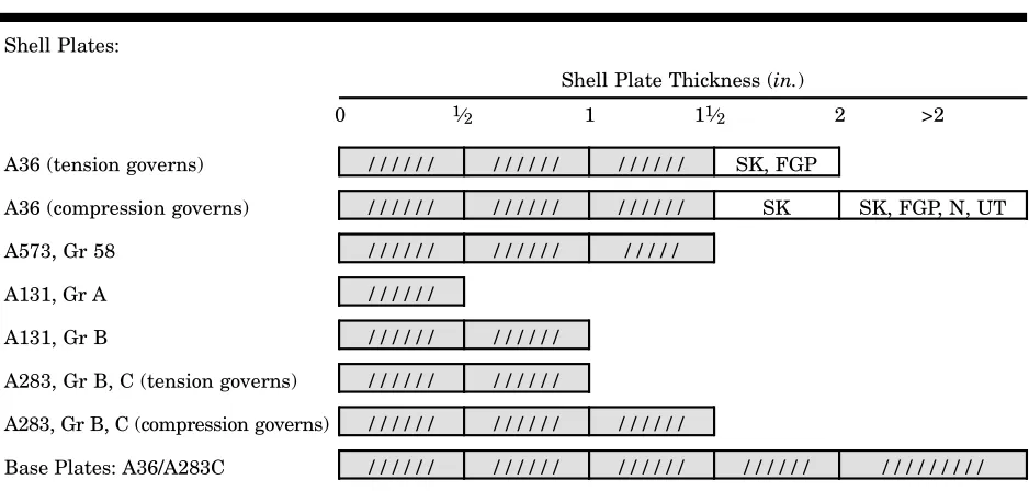
2.2.3.1 Thickness limitations and special requirements. Plate thickness limita-tions and special requirements shall be as discussed in the following subseclimita-tions and as presented in Table 1.
*Canadian Standards Association, 178 Rexdale Blvd., Rexdale, Ont., Canada M9W 1R3.
†US Department of Energy, Technical Information Center, Oak Ridge, TN 37830.
‡Federal Specifications, Superintendent of Documents, US Government Printing Office,
2.2.3.1.1 ASTM A36 shell plates governed by tension stress shall be limited to a thickness of 2 in. (51 mm) and shall conform to supplementary requirements S91
(silicon-killed, fine-grain practice) for thicknesses of 11⁄2 in. (38 mm) or more.
When compression governs, ASTM A36 shell plates greater than 11⁄2 in. (38 mm)
and less than or equal to 2 in. (51 mm) in thickness shall be silicon killed. Plates in compression such as compression rings (biaxial compression), parts of the primary support system, and the primary container shell may not exceed 2 in. (51 mm) in thickness, unless the material conforms to supplementary requirement S91 (silicon-killed, fine-grain practice), is normalized, and is ultrasonically inspected to the acceptance criteria of ASTM A435.
2.2.3.1.2 ASTM A131, grade A, shall not be used in thicknesses greater than
1⁄2 in. (13 mm). ASTM A131, grade B, shall not be used in thicknesses greater than
1 in. (25 mm).
2.2.3.1.3 ASTM A283, grade A steel is to be used only for nonstructural items such as clips, roof sheets, and other low-stressed components less than 1 in. (25 mm) thick. Grade B and C shell plates are limited to a thickness of 1 in. (25 mm) when
tension stress governs and 11⁄2 in. (38 mm) when compression stress governs. Grade
D shell plates are limited to a thickness of 3⁄4 in. (19 mm).
2.2.3.1.4 ASTM A573, grade 58 plates are limited to 11⁄2 in. (38 mm) in thickness.
2.2.3.1.5 Where details are such that tension may occur through the plate thickness, consideration shall be given to the possibility that lamellar tearing may
Table 1 Thickness limitations and special requirements
Shell Plates:
Shell Plate Thickness (in.)
0 1⁄2 1 11⁄2 2 >2
A36 (tension governs) / / / / / / / / / / / / / / / / / / SK, FGP
A36 (compression governs) / / / / / / / / / / / / / / / / / / SK SK, FGP, N, UT
A573, Gr 58 / / / / / / / / / / / / / / / / /
A131, Gr A / / / / / /
A131, Gr B / / / / / / / / / / / /
A283, Gr B, C (tension governs) / / / / / / / / / / / /
A283, Gr B, C (compression governs) / / / / / / / / / / / / / / / / / /
Base Plates: A36/A283C / / / / / / / / / / / / / / / / / / / / / / / / / / / / / / / / /
/ / / / / / Material may be used without special requirements SK = silicon killed
FGP = fine-grain practice N = normalized
2.2.3.1.6 ASTM A36 or A283, grade C steels may be used for base plates regard-less of thickness or temperature. A36 steel ordered as a bearing plate in accordance with ASTM A36, Sec. 5.2, is not acceptable.
2.2.3.2 Substitute material. Material supply or shortages may require the use of substitute materials. Acceptable substitutes may be found in Sec. 14. Stress levels for substitute material shall be limited to those in Sec. 3.
2.2.3.3 Basis of furnishing plates. Plates may be furnished on the weight basis with permissible underrun and overrun according to the tolerance table for plates ordered to weight published in ASTM A6.
2.2.4 Sheets. Sheet materials shall conform to ASTM A570, grade 30, 33, or
36, and ASTM A568.
2.2.5 Structural shapes. All structural shapes for use under the provisions of
this standard shall be produced by the open-hearth, basic-oxygen, or electric-furnace process.
2.2.5.1 Open or nontubular structural shapes shall conform to ASTM A36. When structural shapes are fabricated from plates, the plate materials shall conform to Sec. 2.2.3 of this standard.
2.2.5.2 Tubular structural shapes may be used for structural components such as columns, struts, and miscellaneous parts. Such tubular shapes may be circular, square, rectangular, or other cross section. They may be produced by butt-pressure welding, lap-pressure welding, electric welding, or extrusion processes. Such tubular shapes, when incorporated into the tank structure, shall be protected from corrosion either by suitable coatings on the interior surfaces with access for maintenance or by hermetically sealing each member so that internal corrosion cannot occur. Tubu-lar structural members shall comply with one of the following specifications:
1. Cold-formed square and rectangular structural tubing shall comply with ASTM A500.
2. Hot-formed square and rectangular tubing shall comply with ASTM A501. 2.2.5.2.1 Structural tubing with a circular cross section may be manufactured from plates of any of the specifications permitted in Sec. 2.2.3, provided the welding and other manufacturing processes are in compliance with all sections of this standard.
2.2.5.2.2 Steel pipe may be used as tubular structural members provided it complies with ASTM A139, grade B; ASTM A53 type E or S, grade B; or API 5L, grade B; and provided the minimum thickness of any such material shall comply with the design requirements regardless of the thickness tolerances in any of these specifications. Some pipe specifications allow thickness underruns as high as 12.5 percent. The appropriate specification shall be consulted for allowable underrun and for adjustments made in thickness to ensure that minimum design thicknesses are met.
2.2.6 Copper-bearing steel. Copper-bearing steel with about 0.20-percent copper
content may be used when specified by the purchaser. In other particulars, the steel shall conform to the specifications previously enumerated.
2.2.7 Pins. Pins shall comply with ASTM A307, grade B; ASTM A108, grade
1018 or 1025, conforming to supplemental requirement S9* to meet a minimum
application, but in no case shall the surface finish be rougher than 125 µin.
(3.175 µm).
2.2.8 Canadian steels. Canadian steels acceptable for use under this standard
are CAN/CSA G40.21, grades 38W, 38T, 44W, and 44T. All four grades of G40.21 will have allowable design stresses per class 2 (see Sec. 3).
2.2.9 Cast steel. Castings shall conform to ASTM A27, grade 60-30 (full
annealed).
2.2.10 Forgings.
2.2.10.1 Forgings shall conform to any of the following ASTM specifications: A668, class D; A181, grade II; or A105.
2.2.10.2 Forged and rolled pipe flanges shall conform to the material require-ments for forged carbon-steel flanges as specified in ANSI B16.5.
2.2.11 Filler metals and fluxes. The filler metals and materials shall be of the
same classification as those that have been qualified for each welding procedure in accordance with Sec. 8.2.
2.2.12 Pipe for fluid conductors. Inlet, outlet, overflow, and other pipes, and
all fittings for fluid use shall be as specified by the purchaser.
Steel pipe shall conform to ASTM A53, type E or S, grade B; ASTM A106; or API 5L or equal. Unless otherwise specified, joints may be screwed, flanged, or welded at the option of the constructor. Pipe and fittings from warehouse stock may be used if certified by the warehouse to comply with the provisions of this standard. Pipes other than steel may be specified by the purchaser and agreed upon with the constructor providing they conform to a recognized national or industry standard.
SECTION 3: GENERAL DESIGN
Sec. 3.1 Design Loads
The following loads shall be considered in the design of tank structures and foundations:
3.1.1 Dead load. Dead load shall be the estimated weight of all permanent
construction. The unit weights used shall be 490 lb/ft3 (7,850 kg/m3) for steel and
144 lb/ft3 (2,310 kg/m3) for concrete.
3.1.2 Water load. Water load shall be the weight of all of the water when the
tank is filled to the TCL. The unit weight used for water shall be 62.4 lb/ft3
(1,000 kg/m3). The weight of water in a wet riser, which is supported directly on
foundations, shall not be considered a vertical load on the riser.
3.1.3 Roof design loads.
3.1.3.1 Design snow load. The allowance for the pressure resulting from the
design snow load shall be a minimum of 25 lbf/ft2 (1,205 N/m2) on the horizontal
projection of the tank and external balcony for roof surfaces having a slope of 30°, or less, with the horizontal. For roof surfaces with greater slope, the design snow load allowance shall be zero. The design snow load allowance may be reduced when the tank is located where the lowest one-day mean low temperature is 5°F (–15°C), or warmer, and local experience indicates that a smaller load may be used.
3.1.4 Wind load. Wind pressure shall be calculated by the formula:
Pw= 30Cd
v
100
2
≥30Cd (Eq 3-1)*
Where:
Pw = the wind pressure in lbf/ft2
Cd = the drag factor depending on the surface shape (see Table 2)
v = the actual wind velocity, in mph; however, the value for v is not to be
less than 100 mph (45 m/s)
In coastal regions and certain geographical locations, tanks may be exposed to winds that exceed 100 mph (45 m/s). In such cases, the purchaser shall furnish the design wind velocity for use in Eq 3-1. This velocity shall be taken from a recognized building code.
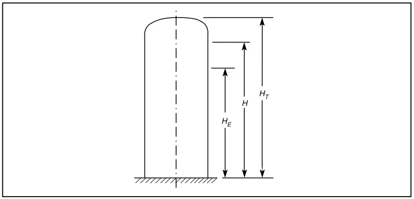
For standpipes more than 125 ft (38.1 m) to TCL and elevated tanks more than 125 ft (38.1 m) to BCL, design for a wind velocity escalated by the root seventh rule:
vh=
H
33
1⁄7
×v33≥ 100 mph (Eq 3-2)*
Where:
vh = mean height velocity
v33 = velocity at 33 ft above grade
H = mean height of tank above escalation elevation measured from grade
in feet
= 1⁄2 (HE + HT). See Figure 1.
HE = 125 ft
HT = tank height to top of roof, in feet
The higher wind velocity shall be applied only to portions of the tank over the escalation elevation. The mean height of the structure above the escalation elevation shall be used to determine velocity.
Where structures may be totally enclosed in a shroud for environmental protection during painting, the structure shall be checked for a load 50 percent greater than the failure load of the shroud, but no more than 50 mph if the shroud strength is unknown. The projected area of the shroud shall be the same height as the structure and 6 ft wider than the projected area of the structure, unless otherwise specified.
Table 2 Wind drag coefficient
C
dType of Surface Cd
Flat 1.0
Cylindrical or conical with apex angle*< 15° 0.60 Double curved or conical with apex angle ≥ 15° 0.50
3.1.4.1 For columns and struts of structural shapes, the projected area shall be calculated. It shall be assumed that struts on the leeward side of the tower are shielded 50 percent by those on the windward side. In the case of columns and sway rods, the wind pressure shall be applied on the projected area of each member. The wind load in any direction on structural columns, other than tubular columns, shall
be taken as 30 lb/ft2 (146.5 kg/m2) on the larger of the two projected areas—one on
the vertical plane containing the longitudinal axis of the column and the vertical axis of the tank and tower, and the other on a vertical plane perpendicular to the first.
3.1.4.2 In the calculation of the wind load on elevated tank structures, it shall be assumed that the entire wind load on the tank walls, roof, and bottom and the proper proportion of the wind load from the riser pipe and tower act on the struc-ture at the center of gravity of these loads.
3.1.5 Seismic load. Structures located in seismic zone 1, 2A, 2B, 3, or 4 shall
be designed for seismic loads as defined in Sec. 13. (See Sec. 3.1.5.2 for an exception.) 3.1.5.1 Structures located in zone 0 do not require design for seismic resistance. 3.1.5.2 The purchaser may specify that seismic design is not required on struc-tures located in zone 1. However, bracing for lateral loads shall be detailed to pro-vide ductility in the event of an overload condition.
3.1.5.3 For elevated tanks, design horizontal forces are calculated by taking the total of deadweight plus water weight and multiplying by the appropriate per-centage. The forces are assumed to act through the center of gravity of the masses that cause them.
3.1.5.4 For flat-bottom tanks resting on the ground, design horizontal forces are calculated by multiplying the deadweight of the tank and the effective mass of the water by the appropriate percentage. The horizontal force due to deadweight is assumed to act through the center of gravity. The effective mass of the water and the heights at which the resulting design horizontal forces are assumed to act may
HE H
HT
3.1.6 Balcony and ladder load. A vertical load (and only one such load in each
case) shall be applied as follows: 1,000 lb (454 kg) to any 10-ft2 (0.93-m2) area on the
balcony floor, 1,000 lb (454 kg) to each platform, 500 lb (227 kg) to any 10-ft2 (0.93-m2)
area on the tank roof, and 350 lb (159 kg) on each vertical section of the ladder. All structural parts and connections shall be proportioned properly to withstand such loads. The previously mentioned load need not be combined with the design snow load specified in Sec. 3.1.3, but it shall be combined with the dead load. The balcony, platform, and roof plating may deflect between structural supports in order to support the loading.
3.1.7 Handrail and guardrail assemblies. Handrail and guardrail assemblies
shall be designed in accordance with OSHA 29 CFR Part 1910. The assemblies shall be designed to resist a simultaneous vertical and horizontal load of 50 lbf/ft (730 N/m) applied to the top rail and to transfer this load through supports to the structure. The horizontal load is to be applied perpendicular to the plane of the handrail or guardrail. Also, all handrail and guardrail systems must be capable of withstanding a single concentrated load of 200 lbf (890 N) applied in any direction at any point along the top, and have attachment devices and the supporting struc-ture to transfer this loading to appropriate structural elements. This load need not be considered to act concurrently with the previously specified 50 lbf/ft (730 N/m) load. Intermediate rails shall be designed to withstand a horizontally applied nor-mal load of 25 lbf/ft (365 N/m).
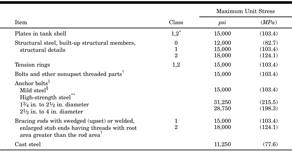
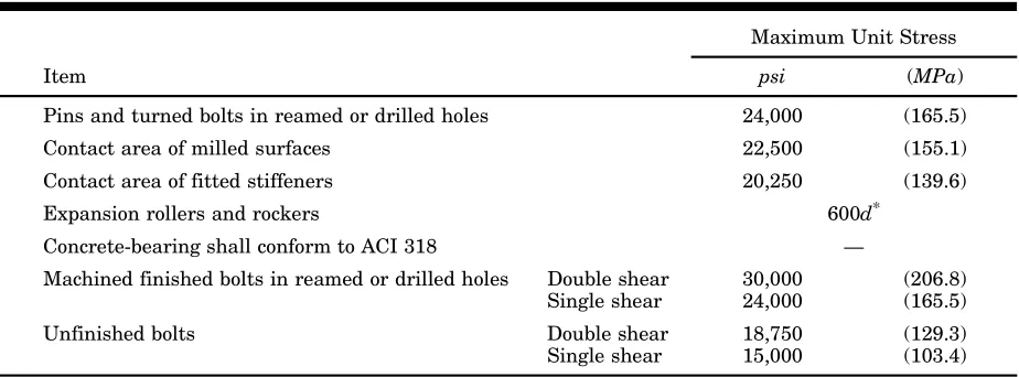
Sec. 3.2 Unit Stresses
Except for roof supports and other exceptions specifically provided for elsewhere in this standard, all steel members shall be so designed and proportioned that, during the application of any of the loads previously specified, or any combination of these loads, the maximum stresses shall not exceed those specified in Tables 4 through 8.
Based on their published minimum yield strength Fy materials are divided into
three classes for determining the allowable design stress (see Table 3). Allowable unit stress values, wherever stated in this standard, shall be reduced by the applicable joint efficiencies.
3.2.1 Width-to-thickness limitations. The ratio of width to thickness of
com-pression elements for configurations other than those addressed in Sec. 3.4.2 and Sec. 3.4.3 shall not exceed the limits shown for noncompact sections in AISC (ASD), Allowable Stress Design, Table B.5.1.
Table 3 Material classes
Fy*
Class psi (MPa)
0 Fy < 27,000 (Fy < 186.2)
1 27,000 ≤Fy≤ 34,000 (186.2 ≤Fy≤ 234.4)
2 Fy > 34,000 (Fy > 234.4)
*Where F
Table 4 Unit stresses—tension
Maximum Unit Stress
Item Class psi (MPa)
Plates in tank shell 1,2* 15,000 (103.4)
Structural steel, built-up structural members, structural det