1070-9932/©2015 TRANSLATIONS AND CONTENT MINING ARE PERMITTED FOR ACADEMIC RESEARCH ONLY.
PER-Autonomous
Transport Vehicles
Autonomous
Transport Vehicles
By Henrik Andreasson, Abdelbaki Bouguerra, Marcello Cirillo, Dimitar Nikolaev Dimitrov, Dimiter Driankov, Lars Karlsson, Achim J. Lilienthal, Federico Pecora, Jari Pekka Saarinen, Aleksander Sherikov, and Todor Stoyanov
Where We Are and What Is Missing
I
n this article, we address the problem of realizing a complete efficient system for automated management of fleets of autonomous ground vehicles in industrial sites. We elicit from current industrial practice and the scientific state of the art the key challenges related to autonomous transport vehicles in industrial environments and relate them to enabling techniques in perception, task allocation, motion planning, coordination, collision prediction, and control. We propose amodular approach based on least commitment, which inte-grates all modules through a uniform constraint-based para-digm. We describe an instantiation of this system and present a summary of the results, showing evidence of increased flexibil-ity at the control level to adapt to contingencies.
Autonomous Transport Vehicles
Autonomous ground vehicles (AGVs) are key components in the development of flexible and efficient transport systems for logistics and industrial site management applications. Com-mercial solutions consisting of fleets of AGVs have been
developed, e.g., for mining (Atlas-Copco mining equipment: http://www.atlascopco.com), automated material handling (Kiva Systems: http://www.kivasystems.com/), forklift automa-tion, and industrial vehicle automation (Kollmorgen: http:// www.kollmorgen.com). Although these systems are viable commercial products, they can still be improved substantially in terms of efficiency and autonomy, and many key parts of the real-world deployment phase are currently ad hoc and manual.
In this article, we describe a set of core requirements for systems comprising a fleet of AGVs. We have distilled these requirements within the ongoing project Safe Autonomous Navigation (SAUNA: aass.oru.se/Research/mro/sauna) because of a decade of cooperation with several industrial partners, including Atlas-Copco, Kollmorgen, Fotonic (www. fotonic.com), and Volvo Construction Equipment (www.vol-voce.com). They point directly to a series of shortcomings in the state of the art (or to insufficient implementation of state-of-the-art results) in robot perception, motion planning, task allocation, coordination, and control.
A first set of challenges relates to the deployment phase. On one hand, the need to handcraft AGV paths for different settings should be avoided. We will refer to this challenge in the remainder of this article as Dep1. (Please see Table 1 for the definitions of the terms used in this article.) On the other hand, it should be possible to specify some or all AGV paths manually, albeit without committing to the particular speed at which these paths are traversed (Dep2). In addition, whether or not paths are specified manually, deadlocks should be avoided automatically (Dep3). Furthermore, perceptual
func-tions, particularly localization, should not rely on additional infrastructure such as environmental markers (Dep4).
A second set of challenges is posed by the nature of the vehi-cles. Industrial vehicles are
usually nonholonomic, which makes automatic trajectory generation a dif-ficult task even when obstacles and coordina-tion are not considered (referred to as V1). Then, the mechanical structure of the vehicles is often non-trivial (e.g., articulated vehicles and detachable trailers), thus increasing the difficulty of calculating individual motions (V2). The requirement to carry payloads adds extra com-plexity to the coordination and motion-planning
problem as the size, shape, and nature of the transported goods may have an influence on the maneuvering capabilities and as the dynamics of each vehicle changes according to the weight of its load (V3).
The key industrial requirements of efficiency and safety pose significant challenges, especially for perception. Reliable perception is negatively affected by high speeds (up to
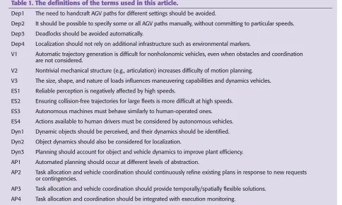
Table 1. The definitions of the terms used in this article.
Dep1 The need to handcraft AGV paths for different settings should be avoided.
Dep2 It should be possible to specify some or all AGV paths manually, without committing to particular speeds.
Dep3 Deadlocks should be avoided automatically.
Dep4 Localization should not rely on additional infrastructure such as environmental markers.
V1 Automatic trajectory generation is difficult for nonholonomic vehicles, even when obstacles and coordination are not considered.
V2 Nontrivial mechanical structure (e.g., articulation) increases difficulty of motion planning.
V3 The size, shape, and nature of loads influences maneuvering capabilities and dynamics vehicles. ES1 Reliable perception is negatively affected by high speeds.
ES2 Ensuring collision-free trajectories for large fleets is more difficult at high speeds.
ES3 Autonomous machines must behave similarly to human-operated ones. ES4 Actions available to human drivers must be considered by autonomous vehicles.
Dyn1 Dynamic objects should be perceived, and their dynamics should be identified. Dyn2 Object dynamics should also be considered for localization.
Dyn3 Planning should account for object and vehicle dynamics to improve plant efficiency. AP1 Automated planning should occur at different levels of abstraction.
AP2 Task allocation and vehicle coordination should continuously refine existing plans in response to new requests or contingencies.
AP3 Task allocation and vehicle coordination should provide temporally/spatially flexible solutions.
AP4 Task allocation and coordination should be integrated with execution monitoring.
Autonomous ground
vehicles are key
components in the
development of flexible
and efficient transport
systems for logistics
and industrial site
3,040 km/h) (called ES1) as is the ability to generate colli-sion-free trajectories for large fleets (ES2). High speeds also impact safety when autonomous vehicles share the work-space with human-operated vehicles. This entails that the autonomous machines must behave in a way comparable with human-operated ones (ES3) and that the actions avail-able to (noncontrollavail-able) human drivers must be considered by autonomous vehicles (ES4).
In many deployed solutions, the dynamic nature of the environment is ignored. Fully dynamic objects (e.g., people, other vehicles, and so on) are often treated as normal obsta-cles, and the vehicles simply stop when encountering them. It is, therefore, important to perceive dynamic objects, identify different types of dynamics, and learn how they are spatially distributed (Dynl). The obtained information should also be considered for localization (Dyn2) and planning (Dyn3) to improve plant efficiency.
The current large-scale industrial deployments of AGVs rarely include more than crude heuristics to optimize, e.g., mission scheduling. Considering the efficiency and flexibility requirements and the complexity of the overall task, it is thus clear that the system must display automated planning capa-bilities at different levels of abstraction (AP1). Continuous task allocation and vehicle coordination should always be able to refine existing plans in response to new requests due to, e.g., changed deadlines, new goals, or newly perceived obsta-cles (AP2). To achieve robustness, task allocation and vehicle coordination should provide flexible solutions (AP3), e.g., sets of collision-free trajectories instead of precise temporal instants, and these reasoning tasks should be integrated with execution monitoring (AP4). In this way, another limitation of current industrial solutions can be circumvented, which is that the resolution of spatial conflicts is often performed offline through manually synthesized traffic rules whose cor-rectness cannot be formally proved.
The SAUNA Approach
The SAUNA project attempts to address these requirements not in isolation but rather within an integrated approach. The
approach builds upon two key principles: least commitment and modularity.
Least commitment means that decisions on the behaviors of vehicles in the fleet are not committed to until necessary. For instance, it may be decided that, because of an automated coordination procedure, two vehicles should not be in a par-ticular area at the same time to avoid a possible collision. However, this decision does not result in a specific trajectory for the two vehicles; rather it is maintained as constraints on the two vehicles’ trajectories. Crucially, these constraints are considered by other decision-making procedures of the inte-grated system, e.g., by the controllers, which synthesize the control actions that will actually displace vehicles. The advantage of least commitment is that decisions on vehicle behavior can be more informed. For instance, suppose that the specific speeds have not been committed to for vehicle trajectories, and, instead, information that excludes kinemat-ically infeasible speeds has been computed; then, a procedure that coordinates multiple vehicles to avoid collisions may leverage the possibility to alter speeds rather than change paths. If specific paths were not committed to and a wider choice of possible paths was maintained, then collision avoidance could also decide whether to alter the speed or to alter the path to avoid a collision.
To implement least commitment, we have chosen to rely on an iterative constraint posting mechanism, whereby con-straints are added to an overall constraint-based representa-tion of vehicle trajectories. The posted constraints progres-sively prune out possible vehicle behaviors. For instance, perception posts spatial constraints representing the drivable area of a map, and coordination imposes constraints that prune out colliding trajectories.
The constraint-based approach directly enables modularity in that the computation and imposition of constraints is per-formed by dedicated modules. The overall schema does not require these modules to implement an automated procedure (addressing Dep2). One or more modules could indeed consist of a user interface for direct input or a pre-existing system used in the particular application domain. For instance, several industrial logistics companies employ handcrafted paths in their deployments and do not wish to deviate from this type of procedure for determining navigable paths.
The common constraint-based representation is grounded on a generalization of the notion of trajectory. A trajectory consists of a path and a temporal profile. (Throughout this ar-ticle, we assume planar paths, which is consistent with the re-quirements of most current industrial applications.) A path is a function :[ , ]p 0 1 "R2#S1 that describes the possible
positions of the reference point of a vehicle and its orienta-tions and has a normalized domain [ , ].0 1 In particular,
( )
p0 denotes the starting pose, and ( )p 1 denotes the final pose of the vehicle’s reference point. A temporal profile
:R "[ , ]0 1
v + denotes the position of the reference point
along the path at different points in time. Together, p (the path of the reference point) and v (its temporal profile)
de-fine a vehicle’s trajectory, i.e., ( ( )).p v t Spatial CSP
Si (Polygon i) Si+1 (Polygon i+1)
Temporal CSP
Time Points and Temporal Constraints
x p
y
tiStart+1 ti+End1 tiStart tiEnd
A trajectory is said to be feasible if perfect execution in nominal conditions can be achieved in the presence of bounds on the relevant state variables of the vehicle model (e.g., the steering angle) and the obstacles in the environment. A feasible trajectory is, in other words, such that it considers a first set of important mission constraints: that motions should be kinematically feasible and should not lead to collisions with known obstacles.
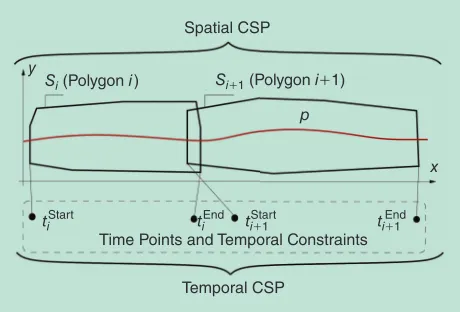
A collection of constraints on a trajectory is called a trajec-toryenvelope. A trajectory envelope is a set of spatiotemporal constraints on a vehicle’s trajectory. It is composed of a spatial envelope and a temporal envelope. The spatial envelope can be seen as a set of n sets of polyhedral constraints
{ , , }
S= S1fSn on the state variables of the vehicle. An example of constraints on ( , )x y is shown in Figure 1. The temporal envelope is a set of n sets of temporal constraints
{ , , },
T= T1fTn one associated to each set of spatial con-straints. The temporal constraints express lower and upper bounds on the time a vehicle’s reference point can be in a par-ticular spatial polyhedron. A more formal definition of trajec-tory envelope is outside the scope of this article, and details can be found in [1]. For the purpose of describing the overall SAUNA approach, it is sufficient to state that a vehicle’s trajec-tory envelope E is a set of spatial and temporal constraints on its reference point, i.e., E=^S T, h.E is said to be feasible if it contains at least one feasible trajectory ( ).p v
The spatial and temporal envelopes of each vehicle consti-tute two constraint satisfaction problems (CSPs) [2]. A solu-tion of the spatial CSP represents a particular choice of path
p for all vehicles, while a solution of the temporal CSP repre-sents a particular choice of temporal profile .v Consequently,
the union of the two CSPs defines the collection of all possible trajectories for all vehicles.
While the trajectory envelopes of all vehicles in a fleet may be individually feasible, the set of trajectory envelopes as a whole may not be. This is because global constraints exist, such as the admissible concurrent use of the floor space (a shared resource). All of these constraints can be seen as implicit spatial and temporal constraints. Therefore, the pro-cess of enforcing the global constraints can be reduced to that of inferring the spatial and temporal constraints entailed by the global ones and imposing them on the set of trajectory envelopes. This process yields what we call a feasible set of tra-jectory envelopes.
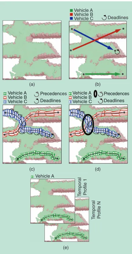
Overall, the SAUNA system is such that commitment increases from goal specification to coordination by means of increasingly tight constraints. This is shown in Figure 2; starting from an empty environment [Figure 2(a)], task allo-cation posts temporal bounds on areas to reach as a result of task allocation [Figure 2(b)], motion planning, in conjunc-tion with percepconjunc-tion, defines temporally sequenced sets of polyhedra that encapsulate admissible paths [Figure 2(c)], and coordination and collision prediction add constraints that disallow collisions and deadlocks [Figure 2(d)]. Con-trollers also avoid commitment to a specific trajectory (Dep2) as the spatial placement of the reference point
remains bounded by constraints, and its temporal place-ment can be altered by selecting an alternative reference tra-jectory [Figure 2(e)].
The fact that every constraint, local to one vehicle or global, can be reduced to spatial and/or temporal constraints suggests a modular approach to feasibility enforcement. In particular, the refinement process, which excludes infeasible trajectories from the set of all trajectory envelopes, can be car-ried out by distinct modules separately, each imposing a
(a) (b)
(c) (d)
(e)
Vehicle A
Deadlines Vehicle B
Vehicle C
Deadlines Precedences Vehicle A
Vehicle B
Vehicle C Deadlines Precedenc Vehicle A
Vehicle B
Vehicle C Deadlines
Precedences Vehicle A
Vehicle B
Vehicle C Deadlines Precedences Vehicle A
Vehicle B Vehicle C
Vehicle A
T
emporal Prof
ile 1
T
emporal Prof
ile N
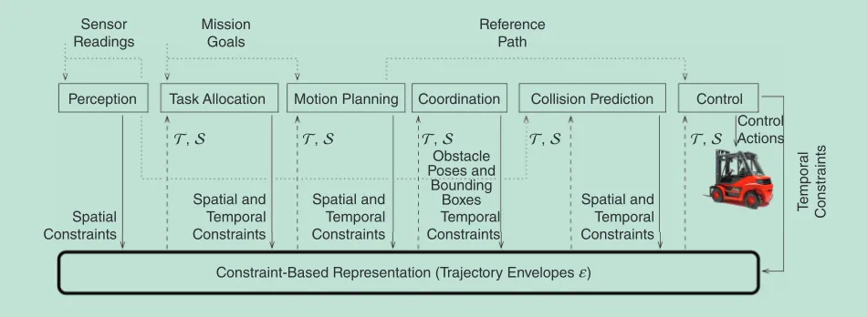
particular set of constraints. In SAUNA, we have divided this collection of reasoning capabilities into six functional mod-ules, as shown in Figure 3.
● Perception is responsible for constructing collections of spatial constraints, which subsume vehicles’ paths, given the perceived drivable area. In addition, perception is responsible for localization and fixed/mobile obstacle tracking. Note that perception dynamically posts spatial constraints, as obstacles may become known gradually over time.
● Task allocation addresses mission goals and computes start-to-destination pairs of regions that vehicles should visit (given the perceived drivable area). It also posts temporal constraints stating the desired deadlines or release times (i.e., when vehicles should be in the designated areas). ● Motion planning uses the perceived drivable area to
com-pute sets of spatial constraints, sequenced by temporal con-straints, which identify how vehicles should displace them-selves across the drivable area to achieve the constraints posted by task allocation. These sequences are trajectory envelopes containing paths that are guaranteed to be kine-matically feasible.
● Coordination is responsible for further refining the trajec-tory envelopes with constraints that exclude deadlocks and collisions between controlled vehicles. The input, calcu-lated by motion planning, is a sequence of overlapping convex polyhedra for each robot. The output consists of temporal constraints that exclude trajectories leading to vehicles being in overlapping areas during overlapping temporal intervals as well as temporal profiles that exceed the known speed limits for vehicles.
● Collision prediction imposes constraints that exclude colli-sions with vehicles that are not autonomously guided and other dynamic obstacles in the environment. It enriches the trajectory envelopes with spatial and temporal constraints, which guarantee the absence of collisions, given current
perception, known trajectory envelopes for controlled vehi-cles, and the predicted behavior of dynamic obstacles. ● Control modules on board the vehicles are responsible for
computing control actions for vehicles in such a way that all spatial and temporal constraints (which have been refined by the previous modules) are enforced. In addition, control-lers measure the performance they achieve in following a reference trajectory. This allows them to dynamically im-pose further constraints that restrict the trajectories of all vehicles in the fleet to maximize the collective performance.
As shown in Figure 3, all modules reason upon the current collection of spatial and temporal constraints (S and ,T respectively) in the common constraint-based representation. They post specific constraints—spatial, temporal, or both—to the common constraint-based representation to refine the tra-jectory envelopes because of their particular inference proce-dures. The modules refine the representation continuously and are triggered by their inputs. Perception may refine the spatial envelopes when sensors detect changes in the environment; task planning is activated when mission goals appear or change, or when the temporal or spatial envelopes of existing trajectories are modified; motion planning recomputes poly-hedra sequencing when new goals appear and/or when spatial constraints change; coordination is triggered when trajectory envelopes overlap both spatially and temporally, a condition that can exist when envelopes are first computed or when tem-poral constraints are added by collision prediction; the tempo-ral and spatial envelopes, as well as newly perceived moving objects, trigger collision prediction; and control modules on board the vehicles adapt control actions in the face of new tra-jectories to follow. The overall result is a constraint network that represents a feasible set of trajectory envelopes for all vehi-cles in the fleet.
In the remainder of this article, we provide a brief over-view of each module and present an instance of the en-tire system. The description also focuses on which of the Constraint-Based Representation (Trajectory Envelopes f)
Sensor Readings
Mission Goals
Reference Path
Control Control Actions Coordination
Motion Planning Task Allocation
Spatial Constraints
Temporal Constraints Obstacle Poses and
Bounding
Boxes Temporal
C
onstraints
Spatial and Temporal Constraints
Spatial and Temporal Constraints
T, S T, S T, S T, S T, S
Spatial and Temporal Constraints
Perception Collision Prediction
challenges shown in the “Autonomous Transport Vehicles” section are tackled and how.
Rich Three-Dimensional Perception
A key role of the perception system in the overall SAUNA architecture is the computation of trajectory envelopes that avoid collisions with obstacles. Extracting the safe drivable area of the environment and posting the appropriate spatial constraints is a central perception task.
Because often neither two-dimensional (2-D) nor three-dimensional (3-D) geometrical information is sufficient, it is important to consider rich 3-D perception, i.e., perception based on geometrical information combined with additional sensor data [e.g., red green blue (RGB) color, reflected light intensity, or temperature values] integrated into environment models that store occupancy together with additional dimen-sions (patterns of dynamic changes, for example).
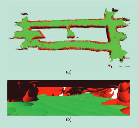
To address challenges ES1, ES2, and ES4, fast and efficient sensor processing and fusion algorithms are necessary. Given the large amount of data obtained from current 3-D and vision sensors, a compact yet accurate spatial modeling tech-nique is vital to the performance of the perception module. The SAUNA perception system uses the 3-D-normal-distri-butions-transform (NDT) [3]—a fast, grid-based Gaussian mixture estimate—to represent and reason about space. The 3-D-NDT representation is accurate yet compact and, thus, is well suited to address the challenges of real-time and long-term operation in an industrial environment. An example top view of a 3-D-NDT map computed from data obtained with an actuated SICK laser range scanner is shown in Figure 4(a), while Figure 4(b) shows a detailed view of the same environ-ment (an underground mine). This representation has been used in multiple autonomous navigation contexts, including
scan registration [3], [4], path planning [5], and loop closure [6], and has also been extended to a rich 3-D context by incorporating color information [7].
An important application of rich 3-D perception is the computation of drivable areas. The 2-D occupancy maps, traditionally used in indoor environments, offer a straight-forward extraction of traversable regions but are often not informative enough to make correct decisions. A simple example of a potential failure in an industrial environment is moving a forklift truck through a door, which can result in collisions with the top of the frame if the fork has not been lowered. Conversely, reasoning about traversable regions in a 3-D-aware framework prevents collisions with the environment or dynamic entities, leading to reduced wear, tear, and accidents. The 3-D-NDT representation is (a)
(b)
Figure 4. (a) The top view and (b) a detailed view of a 3-D-NDT map of an underground mine. Each Gaussian component is represented as an oriented ellipsoid scaled at 3v levels. The color coding represents the results of a terrain traversability algorithm: green represents drivable, and red represents nontraversable space.
(a)
(b)
(c)
readily usable for fast traversability analysis based on 3-D information alone [5], producing a reachability map (as in Figure 4), given a set of geometric and kinematic vehicle parameters. Using additional, nongeometric information available in rich 3-D perception can increase the speed and reliability of the traversability analysis and improve the com-putation of drivable areas.
Another set of perception-related challenges (Dyn1 and Dyn 2) stems from the time scales of operation in industrial environments. Vehicles are often required to operate around the clock on ever-changing factory floors and, thus, must account for variability in the areas that are drivable. Vehicle position estimates in indoor industrial environments are often performed using static landmarks, such as reflective laser or visual beacons. This localization strategy produces accurate results but has several shortcomings, chief among which is beacon occlusion. Localization by comparing range measure-ments to a prerecorded map of the environment is a viable alternative (Dep4), promising shorter system setup times and increased robustness to dynamics and occlusions [8]. In the SAUNA system, we use 3-D range sensors to localize against a dynamically evolving rich 3-D model. The challenge thus becomes to maintain a consistent model of the environment and to learn how to distinguish static parts from dynamic ones. In addition, the different levels and types of dynamics can be identified depending on a chosen time scale. Identify-ing slowly changIdentify-ing elements, such as piles of goods to be transported in a factory automation scenario, is particularly important for localization. Failure to identify slow changes can lead to drift in localization estimates, while quickly changing portions of the environment are of interest to the traversability analysis and collision avoidance tasks. We employ 3-D-NDT maps to perform such dynamic mapping. Our approach extends the iMac representation to create independent Markov chain occupancy grid maps of dynamic environments [9] and employs a novel 3-D-NDT update algorithm [10]. The approach is shown in Figure 5, which shows a busy round-about (the models were created by incrementally updated 3-D range data collected with a Velodyne-HDL64 laser scanner). If dynamics are not considered, an inconsistent model [Fig-ure 5(a)] is produced. Application of our dynamic mapping approach, however, produces separate static [Figure 5(b)] and dynamic [Figure 5(c)] models of the environment.
The output of the SAUNA perception system consists of several modes of information: position estimates, drivable and obstacle areas in the map, and dynamically updated local maps. These results of the perception system are posted to the common constraint-based representation in the form of spatial constraints: 1) the drivability map is uti-lized to obtain a spatial envelope of safe states around a nominal trajectory and 2) the set of allowed vehicle configu-rations is represented as a sequence of overlapping convex polyhedra. Using convex polyhedra is particularly beneficial for the control module (see the “Control” section) as it allows for reasoning about the allowed states of the vehicle in an efficient manner.
Task Allocation
In the context of autonomous industrial vehicles, tasks are often fairly well specified, involving a number of places to be visited and a number of loads to be picked up or delivered. The decisions that the task allocation (see Figure 3) needs to make mainly concern which vehicles to allocate to each task and how to schedule the tasks. The former issue has been studied in the area of multirobot task allocation [11]. The problem of allocating tasks to industrial autonomous vehicles is character-ized by some general features that span across different appli-cation domains. The positions of vehicles are important, as are the load capacities and constraints on the load types; there may also be deadlines on pickups and deliveries; the contents of an order can vary, from a simple start-goal point pair to complex programs with conditionals and loops; and orders may either be known beforehand or arrive during operation.
Presently in SAUNA, we employ a centralized task alloca-tion system (AP1) that satisfies deadlines (when possible) while minimizing the total driving distance to the starting points of orders. Each vehicle can be assigned a sequence of orders, and previous assignments can be reconsidered when new orders arrive (AP2).
The output of the task allocator in our approach is a collec-tion of start-goal point pairs for all vehicles (i.e., no specific path is committed to, AP3). The correct sequencing of tasks is ensured by temporal constraints (e.g., deadlines), which are computed and added to the constraint-based trajectory enve-lope representation. There might also be feedback from motion planning or coordination if those modules detect that a route is not navigable or that a deadline cannot be fulfilled (AP2). This feedback can be included as constraints when a new allocation is computed, e.g., a constraint stating that, at most, one vehicle can move either from A to B or from C to D during a given time interval.
Motion Planning
Many of the problems underlying automated motion plan-ning for autonomous vehicles have been addressed in [12]. As a result, important advancements have been made in separate parts of the overall problem, e.g., in multirobot path planning, which is to date a very active research area [13], [14]. How-ever, these approaches usually rely on unrealistic restricting assumptions, such as that the agents move on a grid [15], or lack the ability to provide important guarantees in the planned motions, e.g., not ensuring deadlock-free situations [16], [17].
lattice, scaled by a cost factor that penalizes backward and turning motions. These paths can be seen as an initial, very tight collection of convex polyhedra, which is then relaxed to obtain a larger spatial envelope for each vehicle.
The planner uses a set of predefined, kinematically feasible motion primitives, which are repeatedly applied to obtain a directed graph that covers the state space. The graph is then explored using A) [20], or anytime repairing A) (ARA)) (an efficient anytime variant) [21], which can provide provable bounds on suboptimality. Effective heuristic functions [22], as well as offline computations for collision detection, are employed to speed up exploration of the lattice. Our approach is inspired by existing lattice-based path planners [23] that are successfully used in real-world applications. It extends exist-ing work by providexist-ing the possibility to compute paths for multiple robots jointly. This ensures that the computed spatial envelopes provide the opportunity for vehicles to yield to oth-ers. All paths are generated such that there exists a time pro-file that yields feasible trajectories (V1, 2), under the assump-tion of car-like and waist-actuated vehicles.
Coordination
The feasibility of a set of trajectory envelopes cannot be ascer-tained without checking global constraints such as floor space. In particular, two trajectory envelopes (of different vehicles) that overlap in both time and space imply the possi-bility of a collision. The temporal and spatial overlap defines a conflict set, i.e., a set of pairs of spatial polyhedra with non-empty intersections and whose associated temporal con-straints also intersect (i.e., it is possible for the vehicles’ refer-ence points to be in a common area at the same time).
Note that since trajectory envelopes constitute both a temporal and a spatial CSP, it is sufficient to eliminate solu-tions from these CSPs that entail the possibility of both tem-poral and spatial overlap. In other words, we are interested in enforcing the feasibility of the set of all trajectory envelopes for all vehicles (AP3). The problem of finding an overall set of trajectory envelopes that is feasible requires a significant computational overhead. Several strategies are possible, one being to refine only the spatial envelopes of spatiotemporally intersecting trajectory envelopes to eliminate the spatial overlap. Another possibility is to add temporal constraints that eliminate temporal overlap. The third option is to per-form one or both refinements, depending on some particu-lar heuristic indicating the impact of the refinement on the feasible trajectories. In SAUNA, we have explored the second option, i.e., the trajectory coordination algorithm resolves concurrent use of floor space by altering when different vehicles occupy spatially overlapping polyhedra. More pre-cisely, the algorithm refines the temporal envelopes by add-ing temporal constraints Ta. This yields a feasible set of tra-jectory envelopes.
Finding a set of additional constraints that make the set of trajectory envelopes feasible can itself be cast as a CSP. The variables of this CSP are conflict sets, i.e., pairs of polyhedra that intersect and whose associated temporal variables may
overlap. The values of these variables are temporal constraints Ta that eliminate this temporal overlap. It can be shown that a solution to this CSP prunes out of the trajectory envelopes those trajectories that lead to a collision between controlled vehicles (ES2). In addition, the identified temporal constraints guarantee the absence of deadlocks (Dep3).
In real deployments of AGVs, it is common practice to dynamically impose deadlines on vehicles reaching their destinations (AP2). Accounting for such constraints renders the previously mentioned
trajectory coordination problem NP-hard. Note also that the minimizing makespan (i.e., the total completion time of all trajectories) is equivalent to resolving the problem with increasingly tight deadlines on all vehicles and is therefore NP-hard. The (centralized) coordi-nation algorithm
pro-posed in SAUNA, detailed in [1], employs a powerful heu-ristically guided, systematic CSP search to find the resolving temporal constraints Ta. The search employs a spatial heuristic for deciding which pair of spatiotempo-rally overlapping polyhedra to separate in time and a well known temporal heuristic [24] to decide which vehicle should take precedence.
Collision Prediction
To address the collision prediction challenge, we focus on (noncontrollable) human-driven vehicles (ES4) and go beyond reactive collision-avoidance solutions to account for possible collisions before they happen. The key idea is to make vehicles proactive, i.e., able to adapt their motion as early as possible to minimize the risk of collision while still moving toward their targets. To do so, our solution uses the continuous flow of refinements to the trajectory envelopes provided by the perception and coordination modules. Each obstacle detected by perception is described by a set of probabilistic attributes that includes an oriented bounding box and color information. Such perceptual information is used to perform short-term tracking of nearby perceived moving objects, with the aim of extract-ing information about their motion, i.e., position and veloc-ity. Motion information is then used to compute probabilis-tic estimates of the future positions of each of the tracked objects. Possible future collision with a specific object is estimated as the probability of future intersection between the bounding box of that object and the spatial envelope of a vehicle. In our current implementation, we compute the probability of intersections using sequential Monte Carlo estimation techniques [25]. For each tracked object, we cre-ate a particle filter that estimcre-ates the future positions of the object. The probability of collision is calculated as the ratio
The key industrial
requirements of efficiency
and safety pose significant
challenges, especially for
of the number of particles that result in intersections and the total number of particles for each object.
If the estimated probability of collision exceeds a pre-defined threshold at some time t in the near future, the tem-poral and spatial constraints are revised to ensure collision-free motion of the vehicle. Note that this entails a (arbitrarily) small possibility of collision. For this reason, all vehicles possess an emergency stop behavior, which relinquishes proactiveness in favor of guaranteeing safety in all situations.
Control
After coordination, trajectory envelopes contain many kine-matically feasible, collision- and deadlock-free trajectories for each vehicle. A tracking controller on board each vehicle is capable of computing control actions for the vehicle given these envelopes, if the temporal profile is fixed (i.e., one solu-tion of the temporal CSP is extracted). This fixed temporal profile, combined with a path contained in the spatial enve-lope, can be used to obtain a reference trajectory.
The aim of a vehicle controller is to compute control actions that follow the reference trajectory as closely as possi-ble. In SAUNA, this computation is implemented by an
embedded optimization process. Deviations from the refer-ence trajectory that fall within the spatial constraints in the trajectory envelope are guaranteed to be deadlock and colli-sion free, both with respect to the other controlled vehicles and static obstacles. In addition, they will not lead to colli-sions with other human-driven vehicles, as collision predic-tion has refined the spatial and temporal envelopes to reflect the predicted motion of the human drivers.
The embedded optimization schema assumes that a spe-cific temporal profile is used. On one hand, this implies a restriction on how the controller compensates for deviations: only through spatial adjustments. On the other hand, the temporal commitment implies that the control problem can be formulated in such a way that it is easily solvable. The tem-poral commitment means that the controller is bound by a fixed schedule, i.e., control actions must lead the vehicle to enter and exit polyhedra at specific times. However, a devia-tion from the path could require a compensadevia-tion that leads to unacceptable accelerations (e.g., because the vehicle is carry-ing a heavy load), therefore makcarry-ing it undesirable to respect the schedule. In SAUNA, we have developed [1] a schema that relies on precomputing multiple alternative temporal profiles. These alternatives can be selected according to the tracking performance: all have the same spatial envelopes but different fixed temporal pro-files, thus leading to alterna-tive reference trajectories.
The embedded optimiza-tion approach used here is known as model predictive control (MPC) because trol actions are computed con-sidering the kinematic model of the vehicle. MPC is one of the most successful embedded optimization schemes and has been used in a wide variety of industrial applications [26]. The application of MPC in the context of tracking a reference trajectory using a nonholo-nomic vehicle has been dis-cussed by several authors, e.g., [27]. In our work, the fact that spatial constraints are convex polyhedral makes it possible to compute control actions in the millisecond (or even micro-second) range. Therefore, it is possible within one sampling time to compute control actions for several alternative reference trajectories and choose the one that provides the best tracking performance.
(a) (b)
(c) (d)
(e) (f)
During execution, control-lers write to the common rep-resentation their current state of execution. This information is modeled as temporal con-straints on polyhedra. These constraints update the time in which vehicles will reach poly-hedra further along in their missions, hence refining the temporal profile of all vehicles. Consequently, a delay of a vehi-cle will be propagated to the temporal profiles of all other vehicles; this, in turn, may require recoordination or a change in task allocation. Fur-ther details on this approach to execution monitoring (AP4) are reported in [28].
Toward an Integrated System
An instantiation of the SAUNA
approach with specific automated reasoning modules has been realized in the robot operating system (ROS) frame-work. Communication among modules is achieved through ROS topics and specialized ROS message formats.
Evaluation of the approach has focused on both individual modules and on the entire system. Two of the most computa-tionally challenging subproblems of the overall fleet manage-ment problem are motion planning and coordination: 1) the former must solve a graph search problem that is exponential already for one vehicle and 2) the latter also has exponential worst case complexity if deadlines are included in .T Despite the high complexity, we have shown [1] that lattice-based motion planning, coupled with constraint-based vehicle coor-dination, renders these individual problems practically feasi-ble in realistically sized environments.
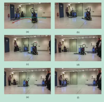
Several evaluations have been performed to validate the overall SAUNA system in terms of practical usability and suitability for realistic scenar-ios. For the former, we have employed two Linde forklift platforms. One of the test sce-narios involved repeatedly posting goal poses for the two forklifts. The limited space in the test environment leads to significant spatiotemporal overlap, thus incurring fre-quent yielding behavior. These vehicles are shown executing a coordinated maneuver when
an unforeseen contingency is created by sending vehicle 1 a brake command [Figure 6(b)], causing vehicle 2 to yield. When the brake command is retracted and vehicle 1 moves out of vehicle 2’s path, vehicle 2 resumes navigation. This behavior is because the coordinator and the two controllers all read from and write to the common representation, thus ensuring collision-free motions. (Videos of the scenarios described here are available at http://aass.oru. se/~ fpa/ SAUNA- movies.)
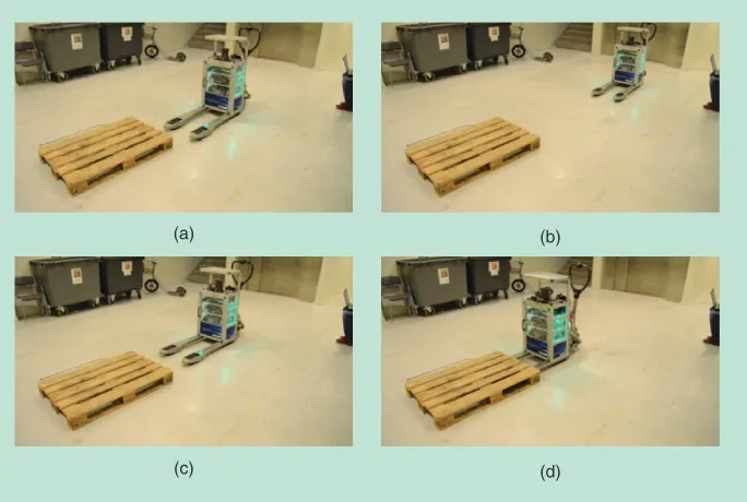
A second scenario is shown in Figure 7, which shows the continuous refinement of the common representation because of perception. In particular, the vehicle’s task is to pick a pallet whose position is only roughly known. When the vehicle reaches the area [Figure 7(a)], its onboard RGB depth sensor re-estimates the pose of the pallet. To achieve
(a) (b)
(c) (d)
Figure 7. The second scenario: (a) a vehicle reaches the loading zone and observes the pose of the pallet, (b) the observed pose requires the vehicle to realign, and (c) the vehicle has realigned and (d) commences the pickup operation. (Photo courtesy of Henrik Andraesson.)
X (m)
Y (m) Spatial Envelopes
28
50 55 60 65 70 75 80 85 90 95
26 24 16 14 12 10
22 20 18
Production Area
Storage Area
Robot #1 Robot #2 Robot #3 Robot #4 Robot #5
the necessarily precise alignment between the vehicle and the pallet, a new goal pose is added to the common representa-tion, which in turn leads the motion planner, coordinator, and all other involved modules to reposition the vehicle appropriately. (Videos of the scenarios described here are available at http://aass.oru. se/~ fpa/SAUNA- movies.)
To evaluate the perfor-mance of the entire system in a realistically sized sce-nario, we performed a set of runs in a simulated in-dustrial production site (using a physical simula-tion in Gazebo). The runs involved one to five vehi-cles in an area that affords long motions. The layout used in the simulation is part of an actual factory in which automatically guid-ed vehicles transit along predefined paths (see Figure 8). The vehicles were required to transport goods between the production and storage areas. Our analysis shows that the vehicle idle time never exceeded 30%, even with five vehicles and under the assumption that the motion planning and coordination are triggered only when previous goals are reached. This extremely unsophisticated form of task dispatching represents a worst case as it forces ve-hicles to enter an idle state while new envelopes are computed and is far less advanced than current industrial practice.
Formal Properties
All modules in the SAUNA system share a common formal representation. This allows to state useful formal properties of the approach. Two of these are: 1) soundness, i.e., whether trajectory envelopes are guaranteed to contain only kinemat-ically feasible and collision- and deadlock-free trajectories and 2) completeness, i.e., whether the approach guarantees finding such trajectories if they exist. It has been shown that the SAUNA system is both sound and complete under rea-sonable assumptions regarding the discretization of working space and resolution of the motion primitives used by the motion planner [28]. By contrast, in most current approach-es (including those used in industrial practice), it is not pos-sible to formally guarantee the absence of deadlocks, and collision avoidance does not account for the other con-straints in the system (e.g., deadlines may be unnecessarily missed as a result of local trajectory adjustments).
Discussion and Future Work
We have proposed a general, modular functional schema designed to be used in different application scenarios. Modu-larity is motivated by the fact that different real-world applica-tions require different levels of automation. In particular, indi-vidual functionalities (task planning/vehicle allocation, motion
planning, perception, control, and so on) are often already provided through proprietary tools that companies do not wish to replace. The SAUNA approach enables the exclusion of one or more modules by establishing a common constraint-based model that represents constraints on trajectories rather than committing to specific trajectories. The use of spatial and temporal constraints in the shared representation provides an intuitive language with which custom user interfaces can inter-act with the fleet. An operator can therefore easily substitute or complement the decision process of an automated procedure without disrupting automated fleet management.
It is worth commenting on the centralized nature of the SAUNA system. This facilitates maintaining a shared represen-tation, which in turn provides the benefit of upholding formal properties and ease of integration of new modules. However, it also poses a hindrance when it comes to scalability—going be-yond tens of vehicles in the current setup is not computationally feasible. For this reason, we will investigate in the near future possible ways to decentralize the approach while still maintain-ing the desirable features obtained so far. Good startmaintain-ing points for doing so are the many related results in the field of multia-gent systems. These include protocols for distributed task alloca-tion, such as contract net [29], decentralized hash tables [30] and auction-based methods [31], decentralized coordination tech-niques [32], and distributed algorithms for safe navigation [33].
Future work in SAUNA will address the primary issue of realizing a complete deployment using industrial vehicles in a controlled environment. In addition, to verify the claim that the SAUNA approach facilitates selective module deployment, we will focus on deploying the system in two industrial application scenarios: an automated milk produc-tion factory and an underground mine site in Sweden. These applications require the integration of different legacy mod-ules and different levels of involvement of human operators. We also plan to make the current implementation of the SAUNA system and of its modules available as open-source ROS packages.
In the longer term, we aim to study specific techniques for addressing the remaining challenges not addressed so far, spe-cifically, V3, ES3, and Dyn3. A further challenge that will be addressed is the integration of meaningful optimization strat-egies for particular applications (e.g., throughput of goods through a warehouse).
References
[1] F. Pecora, M. Cirillo, and D. Dimitrov, “On mission-dependent coordina-tion of multiple vehicles under spatial and temporal constraints,” in Proc. IEEE/RSJ Int. Conf. Intelligent Robots Systems, 2012, pp. 5262–5269.
[2] E. Tsang, Foundations of Constraint Satisfaction. San Diego, CA: Academic Press, 1993.
[3] M. Magnusson, T. Duckett, and A. J. Lilienthal, “3D scan registration for auton-omous mining vehicles,” J. Field Robot., vol. 24, no. 10, pp. 803–827, Oct. 2007. [4] T. Stoyanov, M. Magnusson, H. Andreasson, and A. J. Lilienthal, “Fast and accurate scan registration through minimization of the distance between compact 3D NDT representations,” Int. J. Robot. Res., Special Issue 3D Explo-ration, Mapping, Surveillance, vol. 31, no. 12, pp. 1377–1393, 2012.
Current large-scale
industrial deployments of
AGVs rarely include more
than crude heuristics to
optimize, e.g., mission
[5] T. Stoyanov, M. Magnusson, H. Andreasson, and A. J. Lilienthal, “Path planning in 3D environments using the normal distributions transform,” in
Proc. IEEE/RSJ Int. Conf. Intelligent Robots Systems, 2010, pp. 3263–3268. [6] M. Magnusson, H. Andreasson, A. Nüchter, and A. J. Lilienthal, “Automatic appearance-based loop detection from 3D laser data using the normal distribu-tions transform,” J. Field Robot., vol. 26, nos. 11–12, pp. 892–914, Nov. 2009. [7] B. Huhle, M. Magnusson, W. Straßer, and A. J. Lilienthal, “Registration of col-ored 3D point clouds with a kernel-based extension to the normal distributions transform,” in Proc. IEEE Int. Conf. Robotics Automation, 2008, pp. 4025–4030. [8] J. Saarinen, H. Andreasson, T. Stoyanov, and A. J. Lilienthal, “Normal dis-tributions transform Monte-Carlo localization (NDT-MCL),” in Proc. IEEE/ RSJ Int. Conf. Intelligent Robots Systems, 2013, pp. 382–389.
[9] J. Saarinen, H. Andreasson, and A. J. Lilienthal, “Independent Markov chain occupancy grid maps for representation of dynamic environments,” in
Proc. IEEE/RSJ Int. Conf. Intelligent Robots Systems, 2012, pp. 3489–3495. [10] J. P. Saarinen, H. Andreasson, T. Stoyanov, and A. J. Lilienthal, “3D nor-mal distributions transform occupancy maps: An efficient representation for mapping in dynamic environments,” Int. J. Robot. Res., vol. 32, no. 14, pp. 1627–1644, 2013.
[11] B. P. Gerkey and M. J. Mataric, “A formal analysis and taxonomy of task allo-cation in multi-robot systems,” Int. J. Robot. Res., vol. 23, no. 9, pp. 939–954, 2004. [12] S. M. LaValle, “Motion planning: The essentials,” IEEE Robot. Automat. Society Mag., vol. 18, no. 1, pp. 79–89, 2011.
[13] G. Wagner and H. Choset, “M*: A complete multirobot path planning algorithm with performance bounds,” in Proc. IEEE/RSJ Int. Conf. Intelligent Robots Systems, 2011, pp. 3260–3267.
[14] R. Luna and K. E. Bekris, “Push and swap: Fast cooperative path-finding with completeness guarantees,” in Proc. 22nd Int. Joint Conf. Artificial Intelli-gence, 2011, pp. 294–300.
[15] A. Kleiner, D. Sun, and D. Meyer-Delius, “ARMO: Adaptive road map optimization for large robot teams,” in Proc. IEEE/RSJ Int. Conf. Intelligent Robots Systems, 2011, pp. 3276–3282.
[16] A. W. ter Mors, “Conflict-free route planning in dynamic environments,” in Proc. IEEE/RSJ Int. Conf. Intelligent Robots Systems, 2011, pp. 2166–2171. [17] V. Desaraju and J. How, “Decentralized path planning for multi-agent teams in complex environments using rapidly-exploring random trees,” in
Proc. IEEE Int. Conf. Robotics Automation, 2011, pp. 385–403.
[18] J. Larsson, “Unmanned operation of load-haul-dump vehicles in mining environments,” Ph.D. dissertation, Örebro Univ., School Sci. Technol., 2011. [19] M. Cirillo, T. Uras, and S. Koenig, “A lattice-based approach to multi-robot motion planning for non-holonomic vehicles,” in Proc. IEEE/RSJ Int. Conf. Intelligent Robots Systems, Chicago, IL, 2014, pp. 232–239.
[20] P. Hart, N. Nilsson, and B. Raphael, “A formal basis for the heuristic determination of minimum cost paths,” IEEE Trans. Syst. Sci. Cybern., vol. 4, no. 2, pp. 100–107, 1968.
[21] M. Likhachev, G. Gordon, and S. Thrun, “ARA*: Anytime A* with provable bounds on sub-optimality,” Adv. Neural Inform. Processing Syst., vol. 16, pp. 767–774, 2003.
[22] R. A. Knepper and A. Kelly, “High performance state lattice planning using heuristic look-up tables,” in Proc. IEEE/RSJ Int. Conf. Intelligent Robots Systems, 2006, pp. 3375–3380.
[23] M. Pivtoraiko, R. A. Knepper, and A. Kelly, “Differentially constrained mobile robot motion planning in state lattices,” J. Field Robot., vol. 26, no. 3, pp. 308–333, 2009.
[24] A. Cesta, A. Oddi, and S. F. Smith, “A constraint-based method for project scheduling with time windows,” J. Heuristics, vol. 8, no. 1, pp. 109–136, Jan. 2002.
[25] A. Doucet, N. De Freitas, and N. Gordon, Eds., Sequential Monte Carlo Methods in Practice (Statistics for Engineering and Information Science). Ber-lin Heidelberg, Germany: Springer Verlag, June 2001.
[26] S. Qin and T. Badgwell, “A survey of industrial model predictive control technology,” Control Eng. Practice, vol. 11, no. 7, pp. 733–764, 2003.
[27] D. Gu and H. Hu, “Receding horizon tracking control of wheeled mobile robots,” IEEE Trans. Control Syst. Technol., vol. 14, no. 4, pp. 743–749, 2006. [28] M. Cirillo, F. Pecora, H. Andreasson, T. Uras, and S. Koenig, “Integrated motion planning and coordination for industrial vehicles,” in Proc. 24th Int. Conf. Automated Planning Scheduling, Portsmouth, NH, 2014, pp. 463–471. [29] R. G. Smith. (1980, Dec.). The contract net protocol: High-level commu-nication and control in a distributed problem solver. IEEE Trans. Comput.
[Online]. 29(12), pp. 1104–1113. Available: http://dx.doi.org/10.1109/ TC.1980.1675516
[30] D. Sun, A. Kleiner, and C. Schindelhauer, “Decentralized hash tables for mobile robot teams solving intra-logistics tasks,” in Proc. 9th Int. Conf. Autono-mous Agents Multiagent Systems, 2010, pp. 923–930.
[31] S. Koenig, P. Keskinocak, and C. A. Tovey, “Progress on agent coordina-tion with cooperative auccoordina-tions,” in Proc. AAAI Conf. Artificial Intelligence, 2010, pp. 1713–1717.
[32] B. Faltings, “Distributed constraint programming,” in Handbook of Con-straint Programming, F. Rossi, P. van Beek, and T. Walsh, Eds. New York: Else-vier, 2006, pp. 699–729.
[33] K. E. Bekris, D. K. Grady, M. Moll, and L. E. Kavraki, “Safe distributed motion coordination for second-order systems with different planning cycles,”
Int. J. Robot. Res., vol. 31, no. 2, pp. 129–150, 2012.
Henrik Andreasson, Örebro University, Sweden. E-mail: [email protected].
Abdelbaki Bouguerra, Örebro University, Sweden. E-mail: [email protected].
Marcello Cirillo, Örebro University, Sweden. E-mail: [email protected].
Dimitar Nikolaev Dimitrov, INRIA, Grenoble, Meylan, France. E-mail: [email protected].
Dimiter Driankov, Oerebro University, Sweden. E-mail: [email protected].
Lars Karlsson, Örebro University, Sweden. E-mail: lars. [email protected].
Achim J. Lilienthal, Örebro University, Sweden. E-mail: [email protected].
Federico Pecora, Örebro University, Sweden. E-mail: [email protected]; [email protected].
Jari Pekka Saarinen, Aalto University, Finland. E-mail: jari. [email protected]; [email protected].
Aleksander Sherikov, Centre de Recherche Grenoble, Rhône-Alpes, France. E-mail: [email protected].