Electronic Journal of Structural Engineering (8) 2008
55 1 INTRODUCTION
For a typical steel building frame, the connection be-tween the beam and column is either assumed as pinned, where only nominal moment from the beam is transferred to the column, or rigid or full strength, where full continuity of moment transfer exists. Al-ternatively, Eurocode 3 1993-1-1 (Eurocode 3, 2005) allows building frames to be designed as semi-rigid using the partial strength connection, provided that the moment resistance of the connection can be quantified and the failure mode of the connection should be ductile. When incorporated into the con-struction of a whole frame, the type of concon-struction that uses the partial strength connection is referred to as a semi-continuous construction, due to the partial continuity that exists between the beam and column. Unlike the conventional design approaches (sim-ple and rigid), semi-rigid design requires the mo-ment-rotation relationships of partial strength con-nection, which includes the moment resistance and rotational stiffness (rigidity), to be established prior to its usage in design. In this research, the behavior of partial strength connections with Trapezoidal
Web Profiled (TWP) sections as beams had been studied. The purpose of using TWP sections is to take advantage of the benefits offered by the sections which has thin and corrugated web. The advantages of the TWP will be explained later in this paper. In addition, the use of partial strength connection with TWP section has not been studied yet as far as the knowledge of the authors.
2 CONNECTIONS
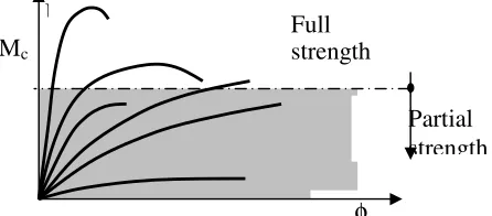
Basically, a beam-to-column connection can be iden-tified by understanding the behavioral characteristics of the particular connection. Conveniently, these be-havioral characteristics can be represented by a rela-tionship between the joint moment and the rotation of the connected member. This useful and important relationship can be depicted by a curve called a mo-ment - rotation curve (M-φ curve). Figure 1 show a typical moment-rotation curve for a bolted connec-tion which varies Based on the moment-rotaconnec-tion curve, a connection can be classified as full strength, partial strength, and pinned joint connection.
Structural Behaviour of Trapezoidal Web Profiled Steel Beam Section
using Partial Strength Connection.
M. Md. Tahir, A. Sulaiman, A Saggaff
Steel Technology Centre, Universiti Teknologi Malaysia
Skudai, Johor 81310, Malaysia, Email [email protected]
ABSTRACT: Connections are usually designed as pinned which associated with simple construction or rigid which is associated with continuous construction. However, the actual behaviour falls between these two ex-treme cases. The use of partial strength or semi-rigid connections has been encouraged by EC3 code and studies on hot-rolled steel sections on semi-continuous construction for braced steel frames have proven that substantial savings in steel weight and the overall construction cost. The objective of this paper is to present the performance of full scale testing of sub-assemblage steel beam and isolated beam-to-cloumn with partial strength connections for Trapezoid Web Profiled (TWP) steel sections. The TWP steel section is a built up section where the flange is of S355 steel section and the corrugated web of S275 steel section. Two full scales testing with beam set-up as sub-assemblage and beam-to-column connection have been carried out for flush and extended end-plate connections as partial strength connections. It was concluded that the use of ex-tended end-plate connection has contributed to significant reduction to the deflection and significant increase to the moment resistance of the beam than flush end-plate connection.
Figure 1. Typical moment-rotation curves for beam-to-column connection.
A full strength connection is defined as a connec-tion with a moment resistance, MR at least equal to
the moment resistance of the connected member or moment resistance of the beam Mc (Allen, P., Mike F,
1994). A partial strength connection, on the other hand, is defined as a connection with moment resis-tance less than the moment resisresis-tance of the con-nected beam member. Whereas, a nominally pinned is defined as a connection, that is sufficiently flexi-ble with a moment resistance not greater that 25% of the moment capacity of the connected member. In understanding the behavior of any connection, data on the moment and rotation of the connection has to be studied. Usually, the data is obtained through ex-perimental works. Observation and important values such as the failure mechanism and the resistance of the tested connection are then determined from a curve plotted as moment versus rotation of the con-nection.
Historically, moment connections have been de-signed for resistance and stiffness only. It was only quite recently that rotational capacity of moment connections have been regarded as important espe-cially for designing partial strength joints or under seismic conditions. Eurocode 3 1993-1-1 (Eurocode 3, 2005) and Steel Construction Institute (Allen, P., Mike F, 1994) have recognized it’s important and suggested a so called ‘component method’ for de-termining the moment resistance of the connections. This component method takes into consideration the failure mode of each component that interacts to-gether to the formation of the connection. The failure mode of each component is checked base on the failure zone that divided into three major zones namely tension, shear, and compression zone as shown in Figure 2.
Figure 2.: Critical zones checks in ‘component method’ 2.1 Partial Strength Connections
The experimental works on the behavior of the semi-rigid (partial strength) connections have constantly being conducted since then till the present time. Some of the experimental works carried out by other researchers on connections are described in this pa-per. Beg et al. (2004) carried out a series of tests and numerical simulations. An analytical method was presented of which was fully consistent with the pre-sent rules of EC 3 in estimating the moment resis-tance of the connections. Anderson and Najafi (1994) investigated the performance of composite connections on major axis using end-plate joints. The study has found that the moment resistance in composite connection has increased significantly. Bernuzzi et al. (1996) carried out research on the performance of semi-rigid connections under cyclic reversal loading with the aim of developing simple design criteria for semi-rigid steel frames in seismic zones. De Carvalho et al. (1998) investigated on the bolted semi-rigid steel connections that used angles to connect the bottom flange and the beam’s web to the column. De Lima et al. (2002) have conducted a series of tests followed by finite element simulations in predicting the moment resistance and rotation ca-pacity of minor axis beam-to-column semi-rigid connections. Al-Jabri et al. (2005) has conducted a series of tests on beam-to-column connections sub-jected to elevated temperature with the aim of pro-ducing moment-rotation-temperature curves for va-riety of semi-rigid connections.
All of the works mentioned previously were car-ried out with hot-rolled sections as the connected beams and columns. However, Ribeiro et al. (1998) had conducted an experimental study on the struc-tural behaviour of end-plate connections with 12 cruciform welded profiled beams. Several observa-tions had been drawn which indicated that the thick-ness of end-plates and diameter of bolts slightly in-fluenced the rotations of the beams and end-plates (about 4% between the extreme cases).
φ
Partial strength Mc
M Full
strength
Tension Zone
Compression Zone
Horizontal Shear Zone
Electronic Journal of Structural Engineering (8) 2008
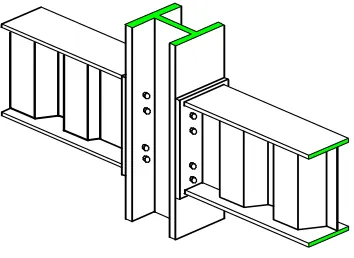
57 In this paper, the experiment works on connection have been further extended to the use of partial strength connection with Trapezoidal Web Pro-filed(TWP) steel section. Two types of partial strength connections that are commonly used are ex-tended end-plate connection and flush end-plate connection as shown in Figure 3(a and b) were pro-posed for the experimental tests. These connections consist of a plate, which is welded to the beam’s end in the workshop, and then bolted to the column on site. In the case of extended end-plate, the plate is extended above the flange of a beam and with one row of bolt.
Figure 3(a) Extended end-plate connection
Figure 3(b) Flush end-plate connection 2.2 Why partial strength connection?
In the design of braced multi-storey steel frames, the steel weight of the connections may account for less than 5% of the frame weight; however, the cost of the fabrica-tion is in the range of 30% to 50% of the total cost (Al-len, P., Mike F, 1994). The fabrication of partial strength connections may be marginally more expensive since some degree of rigidity has to be provided. However, by using partial strength connections instead of simple con-nections, beam sizes could be reduced and significant overall savings of frame weight could be acquired (Tahir,
1997; Couchman, G. H, 1997). In Malaysia where the cost of labour is relatively low compare with the Europe, the use of the proposed connections will be an added ad-vantage. It has been reported that the savings in steel weight of using partial strength connection alone (non-composite) in multi-storey braced steel frames using British hot-rolled section was up to 12% (Tahir, 1997). The overall cost saving was up to 10% of the construc-tion cost, which is quite significant according to the cost of labour in the United Kingdom (Tahir, 1997). The sav-ing in the overall cost can be further enhanced by the use of standardized partial strength connection as reported by Allen (Allen, P., et al, 1994) as described below:-
• A reduction in the number of connection types may lead to a better understanding of the cost and type of connection by all steel players such as fabricator, de-signer, and erector.
• A standardized connection can enhance the devel-opment of design procedures and encourage in the development of computer software.
• The use of limited standardized end-plates or fittings can improves the availability of the material leading to reduction in material cost. At the same time, it will improve the order procedures, storage problems and handling time.
• The use of standardized bolts will reduce the time of changing drills or punching holes in the shop which lead to faster erection and less error on site. The drilling and welding process can be carried out at shop as the geometrical aspects of the connection have already been set. This leads to fast and quality fabrication.
section of the same weight lead to larger load carry-ing capacity and greater beam span.
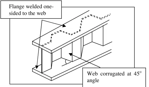
Figure 4. Trapezoidal Web Profiled Steel Section
3 EXPERIMENTAL TESTS
The experimental tests were divided into two tests. A series of two isolated bare steel beam-to-column joints and two bare steel sub-assemblage beam-to-column joints were tested on a full-scale basis. 3.1 Isolated Tests
The first test was an isolate beam-to-column connec-tion whereby a point load was applied to the end of the beam as shown in Figure 5. The purpose of this test is to obtain the relationship between moment re-sistance and the rotation of the connection which is also known as M- curve. From this M- curve, the moment resistance of the connection can be ob-tained. The test also showed the failure mode of the connection that will indicate the ductility of the con-nection. The height of the column was kept at 3 m to represent the height of a sub-frame column of multi-storey steel frame. The column was restrained from rotation at both ends whilst the beam was restrained from lateral movement as shown in the Figure 5. The load was applied at a distance of 1.3 m from the face of the column. This distance was deemed adequate to cover the distance of the contra flexural point be-tween the negative end moment of the joint and the positive moment of the beam. Two types of connec-tion namely flush plate (FEP) and extended end-plate (EEP) connection were tested with the geomet-rical configuration of the connection is given in Ta-ble 1. TaTa-ble 1 also presents the geometrical configu-rations of the sub-assemblage beam that will use the same connections proposed for the isolated tests.
Electronic Journal of Structural Engineering (8) 2008
59 length of the beam so that a bending situation was assured.
For both tests, the instrumentation system had been set-up and the specimen had been securely lo-cated in the rig, the data collection software in the computer was checked to make sure that all channels connecting to the instruments on the specimen indi-cated a properly working condition. Correction fac-tors from calibration and gauge facfac-tors from manu-facturer were input into the software prior to each test. An increment of about 5kN was adopted in or-der to have a gradually applied loading condition. The specimen was then loaded up to one-third of the analytically calculated moment of resistance, and was expressed in term of the point load applied for easier monitoring. After reaching the one-third value, the specimen was unloaded and then re-loaded. This sequence was done so that the specimen was set-up to an equilibrium state before actual load-ing was applied. After re-initializload-ing the instrumen-tation system, the specimen was loaded as described above, but the load applied was not restricted to the one-thirds value. Instead, the specimen was further loaded until there was a significantly large deflection of the beam observed. The load application was con-tinually applied after this point but the increments were controlled by the deflection instead of the load as before. A deflection of 3 mm was adopted as a suitable increment at this stage. This procedure was continued until the specimen had reached its failure condition. The ‘failure’ condition was deemed to have been reached when the beam deformed at the mid-section of the beam. All important data such as the applied load, the deflection of the beam and the rotation of the connection were recorded. Readings from the load cell and linear variable displacement transducers (LVDTs) were recorded via the data log-ger on to the hard disk of the computer.
However, the rotational values of the beam and column were recorded manually from the digital dis-play unit of the Lucas rotational inclinometers. This is because the instrument does not have the capabil-ity of connecting to the data logger and recording the measurements directly. One of the inclinometers was mounted mid-depth at the web of the beams at a dis-tance of about 100 mm from the face of the column flange. This inclinometer provided the rotational values of the beam, φb, upon loading. The other in-clinometer was placed at the centre of the column, thus provided the rotational values of the column, φc. The overall rotation of the joint, φ, was then taken as the difference between φb and φc.
Roller
Strong Floor Column
Base Plate
Base Beam Bracing
Beam Connection
Load Cell
Hydraulic Jack Spreader
LTB Bracing
Figure 6. Test rig set-up for sub-assemblage tests
4 DISCUSSION OF RESULTS
The results of the experiments were focused on the behavioural characteristics of moment versus rota-tion curve for the flush plate and extended end-plate connections in the isolated tests, and the mo-ment resistance and the deflection at mid-span for the beam in sub-assemblage tests.
4.1 Isolated beam-to-column tests 4.1.1 Modes of Failure
still corresponded to the initial stiffness of the con-nections.
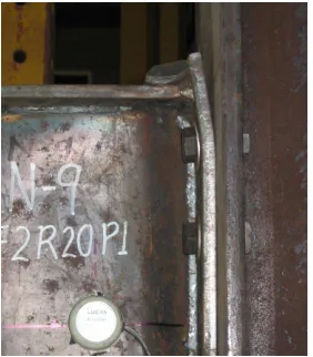
The first visible deformation observed was around the vicinity of the connection; and this de-formation was limited to the tension region of the joint due to the tension forces exerted through the top bolt rows. For the flush end-plate connection (N9), the form of the deformation was the translation of the tip of the end-plate away from the face of the column. This corresponded to the first sign of yield-ing of the end-plate, which could lead to the defor-mation of end-plate failure. The defordefor-mation of the connection appeared to be symmetrical on both sides of the connection when looking from the plan view of the joint. Further loading of the specimens has re-sulted into more deformation of the tip of the end-plate. Figure 7 shows the deformation of the flush endplate of specimen N9 that brought about the fail-ure mode of the connection.
Figure 7 Deformation of end-plate for N9 specimen (F2R20)
For the extended end plate connection tests N7 (E3R20), higher capacity was expected due to the addition of one row of bolts at the extended top por-tion of each end plate. Hence, at the initial stage of loading, there was apparently no visible deformation in all specimens even up to the one third of the pre-dicted load. Gradually, however, at about two third of the predicted load, the end-plates (at the tension region of the connections) had begun to show some small deformation. Unlike the flush end-plate, since there existed one row of bolts at the extended top portion of the end plate, the deformation of the con-nection translated the end-plate away from the face of the column in a ‘Y-shape’ form. Again, this de-formation corresponded to ductile typed of mode of failure and appeared to be symmetrical on both sides of the connection when looking from the plan view of the joint. Figure 8 shows the deformation of the
extended end plate in the form of a ‘Y-shape’ de-formation of specimen N7 at failure. There was hardly any deformation on the connected column throughout the experiment test for the isolated tests. This was as expected since the columns for all speci-mens (UC 305 x 305 x 118) for both flush and ex-tended end-plate connection were designed to ade-quately sustain the compression force from the bottom flange of the beam.
Figure 8 Deformation of end-plate for N7 specimen (E3R20)
4.1.2 Moment versus rotation curves (M- curves)
The data gathered from the test results are presented by plotting the moment versus rotation curves. Fig-ure 9(a) is the curves for FEP connection whereas Figure 9(b) is the curves for EEP connection.
0.0 50.0 100.0 150.0 200.0
0.0 20.0 40.0 60.0 80.0
Rotation (mRad)
M
o
m
en
t
(k
N
m
)
Figure 9(a) Moment-rotation curve for FEP connection. MR=132kNm
MU = 158kNm
5.2(rotation from sub-assemblage)
Electronic Journal of Structural Engineering (8) 2008
Figure 9(b) Moment-rotation curve for EEP connection The maximum load of each plot clearly represents the ultimate load that can be sustained by the respec-tive joint. A method known as ‘knee-joint’ was adopted to predict the moment resistance of the con-nection (Tahir, 1997; Brown, 1996, Kim 1988) This method is basically base on the intersection between straight line drawn from linear and non-linear inter-action. The capacity can then be determined by pro-jecting horizontally from the intersecting point be-tween these two lines to the vertical axis of moment. As a result, the predicted moment resistance of the connection was established. The result was then compared with the theoretical value calculated from the component method proposed by Steel Construc-tion Institute. Table 2 summarizes the results based on the moment versus rotation curves for the speci-mens and the calculated theoretical moment resis-tance from component method.
Table 2. A summary of experiment moment and theoretical
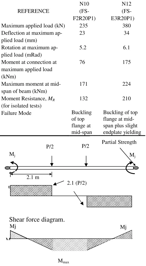
The results indicate that the predicted moment resis-tance of the connection from the experimental tests using knee-joint method has a good agreement with the moment resistance calculated from the compo-nent method as proposed by the SCI. The ratio be-represent the behaviour of a beam in a typical struc-tural steel frame since the tested specimens were only 1.5 m in length setting up as cantilever. To de-pict the actual or ‘close-to-reality’ situation, sub-assemblage tests were carried out with a beam length of 6 m. In addition to the information obtained as those in the isolated joint tests, the observation was also focused on the effect of a long beam, specifi-cally, the mid-span deflection and the moment resis-tance of the beam. To quantify the deflection and moment resistance of the beam, the result from the isolated tests were be used which will be described later in this paper. The sub-assemblage tests sisted of two specimens with the geometrical con-figuration is shown in Table 1. For the first specimen (referred to as N10 or FS-F2R20P1), the beam was connected to the column using a partial strength flush end plate connection. This joint actually is identical to specimen N9 in the isolated tests. The other specimen (referred to as N12 or FS-E3R20P1) was fabricated with a partial strength named as ex-tended end plate connection, which is identical to specimen N7 in the isolated tests.
4.2.1 Mode of Failure.
At the very initial stage of loading, there were no apparent visual deformations observed in both ex-periments. As in the isolated tests, this was expected since the application of loads was intended for all of the components of the joint to be ‘embedded’ in the configuration (or to be in equilibrium). In addition, this stage was also meant for checking all of the in-strumentation system prior to the actual commence-ment of the test.
Each specimen was loaded gradually until there was an indication that a ‘failure’ has been obtained, and the test was brought to a stop. During all of the tests, there was no occurrence of any vertical slip at the interface between the end-plate and the column. This was mainly due to the adequate tightness of the bolts carried out during the installation and after the initial stage of loading. The only significant defor-mation was the deflection at the centre of the beam (noticeable from the reading of mid-span LVDT). The unloading of the loads was done at about one third of the predicted loads for both specimens. The recovery of the loads in all specimens was in a line-arly elastic manner, which corresponded to the initial stiffness of the connection.
MR=210kNm
MU=266kNm
The first visible deformation around the vicinity of the connection was limited to the tension region of the joint. For specimen N10 (FS-F2R20P1), the form of the deformation was a typical flush end plate connection deformation, where end plate deformed away from the face of the column. This corre-sponded to the first sign of yielding of the end plate. The deformation of the connection appeared to be symmetrical on both sides of the connection. How-ever, this deformation only occurred after the first limit of the mid-span deflection had been reached. The first limit is the limit suggested by BS 5950:2000 Part 1 for brittle material underneath the beam and the loading is meant for un-factored im-posed loading only. The first limit was taken as:
mm L
5 . 17 360
300 6000
360 =
+
= ,
where, L is taken as the distance from centre-to-centre of column. At about the same time of yielding of the end-plate occurred (P = 164.2 kN and δ = 15.68 mm), there was a ‘bang’ sound. The loading sequence was stopped and the specimen was checked for any unexpected deformation. No appar-ent deformation was found and the experimappar-ent was continued. A possible explanation of this was the sound might be due to the ‘natural’ adjustment of the specimen against the bending of the beam and the tension of bolt in the connection.
Further loading was applied to the specimens which has resulted into more deflection at the mid-span of the beam. A small deformation was observed on the tip of the end-plate. The second limit of de-flection was set at this stage. The second limit is suggested by BS 5950:2000 Part 1 for beam with other than brittle material underneath the beam. The limit is taken as:
mm L
5 . 31 200
300 6000
200 =
+
= ,
At this stage, a sudden drop in the applied load has been observed even though the mid-span deflection had increased. A careful visual inspection on the specimen revealed that a local buckling had occurred at the top flange of the beam. In addition, it was ob-served that the buckling had occurred on the side where the width of the outstand element of the TWP beam, bf, was the largest. Figure 10 shows the buck-ling of the top flange of specimen N10 that brought about the failure of the specimen. Figure 11, on the other hand, shows the flush end plate connection that suffered only small deformation of the end-plate of the connection.
Figure 10. The buckling of the top flange of specimen N10.
Figure 11. Small deformation of the end-plate of the connec-tion.
As for specimen N12 (FS-E3R20P1), a larger load is expected in order for the extended end plate to deform significantly as the resistance of EEP con-nection is greater than the FEP concon-nection. A typical extended end plate connection deformation is in the form of translation of the top part of the end plate in a ‘Y’ shape manner away from the face of the col-umn. The deformation of the connection, which was symmetrical on both sides of the connection, corre-sponded to the first sign of yielding of the end-plate. Since a larger load was expected, the deformation of the extended end-plate was not apparent at all when the first limit of deflection was reached. The first limit was taken as in the previous test (specimen N10), which is 17.5 mm. Ironically, at about the same time as in the previous test (P = 243.7 kN and
ad-Electronic Journal of Structural Engineering (8) 2008
63 justment of the specimen against the bending and the tension of the bolt in the connection.
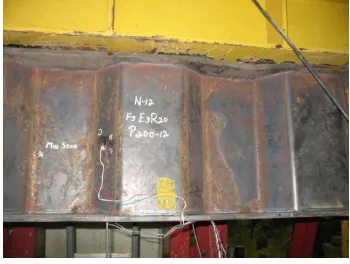
Further loading of the specimen has resulted into more deflection at the mid-span of the beam, though there was still not much deformation observed on the end-plate. The second limit of deflection was taken, as before, at 31.5 mm, but before this limit was reached, another ‘bang’ sound was heard followed by a drop in the applied load and the mid-span de-flection. A careful visual inspection on the specimen has shown that a local buckling has occurred at the top flange in the middle of the beam and at the loca-tion where the width of the outstand element, bf, was the largest. Figure 12 shows the local buckling of the top flange of specimen N12 that brought about the failure of the specimen, whilst Figure 13 shows the extended end plate connection that suffered only minimal deformation.
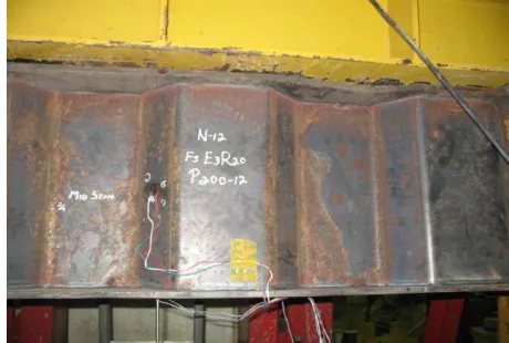
Figure 12 Local buckling of the top flange of specimen N12.
Figure 13 Small deformation of extended end-plate connec-tion in “Y-shape” manner.
4.2.2 Load versus Mid-Span Deflection and Load versus Rotation
Figure 14 shows the graph of load versus rotation and Figure 15 show the graphs of load versus mid-span deflection for the flush end plate connection for specimen N10. On the other hand, Figure 16 shows the graph of load versus rotation and Figure 17 shows load versus mid-span deflection for the ex-tended end plate connection for specimen N12. For load versus deflection graphs as shown in Figure 15 and 17, the results of the deflection limit L/360 and L/200 as suggested by BS 5950:2000 Part 1 are shown in the respective graphs. The limit of defec-tion at L/360 was reached when applied load was at 185kN for FEP connection and 240kN for EEP con-nection. This shows that the use of EEP connection which is more stiff connection has resulted to an in-crease in the loading resistance up to 29.7%.
Figure 14 Load versus rotation for FEP (N10)
Mmax
Figure 16 Load versus rotation for EEP (N12)
P vs Mid-Span Deflection - EEP(N12)
0.0
Figure 17 Load versus rotation for EEP (N12)
Since the flush end-plate and extended endplate connections used in these experiments were identical to the ones tested in specimen N9 and N7 respec-tively, the plots of moment versus rotation were ap-plicable to be applied to the sub-assemblage tests. Figure 18 shows the plots for the full-scale isolated joint test specimen N9 (FEP) which is identical to specimen N10, and N7 (EEP) which is identical to specimen N12. Based on these curves and the mo-ment versus rotation curves of the two ‘control’ con-nections (N7 and N9 of the Isolated tests), the results are summarized and tabulated as in Table 3.
It was noticed that although both specimens failed due to the buckling of the top flange at the centre of the beam, the connections possessed a ductility char-acteristic according to Steel Construction Institute (Allen, et al, 1994) with a rotation capacity of 34 shows that the use of extended end-plate connection has resulted to an increase of moment resistance to 59.1% as compared with the flush end-plate
connec-tion. The values of the maximum moment at mid-span of beam were determined as follows:
Table3Test results of the Sub-assemblage tests REFERENCE maximum moment in the sub-assemblage beam.
j
The value of P in Figure 18 is taken from the maxi-mum load applied to the specimen. The value of Mj
Partial Strength
P/2 P/2
2.1 m
2.1 (P/2)
Electronic Journal of Structural Engineering (8) 2008
65 is derived from the isolated M- curve. The value of the rotation of the connection in sub-assemblage test is plotted versus the applied load as shown in Figure 14 for FEP and Figure 16 for EEP. After es-tablishing the rotation of the connection from these figures at maximum applied load, the related rotation value is superimposed to Figure 9(a) for FEP and show that the connection resistance in the actual sub-assemblage test has not reached full moment resis-tance of the connection. The sub-assemblage con-nections have only utilized about 57.6% for FEP connection and 83.3% for EEP connection of the moment resistance from the isolated test.
5 CONCLUSIONS
Based on the results obtained, several observations have been made which lead to the following conclu-sions:
i. The moment resistance of EEP connection is more than the FEP connection by 59.1%. ii. The failure mode for the flush end-plate in the
isolated tests is end-plate yielding, whilst for the extended endplate, the failure mode is end-plate yielding and bolt slipping.
iii. The mid-span deflection of the sub-assemblage specimens has reached its limit at L/360 before the moment resistance of the end-plate connec-tions has been reached. The limit also shows
v. Maximum moment resistance of the TWP can be quantified by performing isolated test and sub-assemblage test. The results have con-cluded that the sub-assemblage connections have only utilized about 57.6% for FEP con-nection and 83.3% for EEP concon-nection of the
moment resistance developed in the isolated connection tests.
ACKNOWLEDGEMENT
The authors would like to acknowledge special thanks and gratitude to CIDB for funding this project under Vot 73049. Special thanks also to two re-search assistants that involved in this project namely Tan Cher Siang and Shek Poi Ngian.
REFERENCES
Al-Jabri, K. S., Burgess, I. W., Lennon, T. and Plank, R. J. (2005). Moment Rotation-Temperature Curves for Semi-Rigid Joints. Journal of Constructional Steel Research. Vol. 61, pp 281-303.
Allen, P., et al, Steel Construction Institute and British Con-structional Steelwork Association. (1994). Joints in Steel Construction. Volume 1: Moment Connections. London. Anderson, D. and Najafi, A. A. (1994). Performance of
com-posite Connections: Major Axis Endplate Joints. Journal of Constructional Steel Research. Vol. 31, pp 31-57.
Beg, D., Zupancic, E. and Vayas, I. (2004). On the Rotation Capacity of Moment Connections. Journal of Construc-tional Steel Research. Vol. 60, pp 601-620.
Bernuzzi, C., Zandonini, R. and Zanon, P. (1996). Experimen-tal Analysis and Modelling of Semi-Rigid Steel Joints Un-der Cyclic Reversal Loading. Journal of Constructional Steel Research. Vol. 38, No. 2, pp 95-123.
British Standards Institute BS 5950-1. (2000). Structural Use of Steelwork in Building Part 1: Code of Practice for Design – Rolled and Welded Sections. British Standards Institution, London.
Brown, N. (1995). “Aspects of Frame Sway design and Ductil-ity of Composite Endplate Connections”. PhD Thesis. Uni-versity of Warwick, United Kingdom.
Couchman, G. H. (1997). Design of Semi-Continuous Braced Frames, Steel Construction Institute Publication 183, Sil-wood Park, Ascot, Berkshire SL5 7QN, U.K.
De Carvalho, L. C. V., De Andrade, S. A. L. and Da S. Vellas-co, P. C. G. (1998). Experimental Analysis of Bolted Semi-Rigid Steel Connections. Journal of Constructional Steel Research. Vol. 46, No. 1-3. Paper No. 131.
De Lima, L. R. O., De Andrade, S. A. L., Da S. Vellasco, P. C. G. and Da Silva, L. S. (2002). Experimental and Mechani-cal Model for Predicting the Behaviour of Minor Axis Beam-to-Column Semi-Rigid Joints. International Journal of Mechanical Sciences. Vol. 44, pp 1047-1065.
Eurocode 3. (2005). Design of Steel Structures: EN 1993-1-1: Part 1.1: General Rules and Rules for Buildings.
Kim, Y. W., The behaviour of beam-to-column web connec-tions with flush end-plate”, M.Sc thesis, University of Warwick, U.K, 1988.
Ribeiro, L. F. L., Goncsalves, R. M. and Castiglioni, C. A. (1998). Beam-to-column Endplate Connections – An Ex-perimental Analysis. Journal of Constructional Steel Re-search. Vol. 46, No. 1-3. Paper No. 304.
Tahir, Md. M (1997). “Structural and Economic Aspects of the Use of Semi-Rigid Joints in Steel Frames”. PhD Thesis. University of Warwick, United Kingdom.