ESTIMATE OF DTM DEGRADATION DUE TO IMAGE COMPRESSION FOR THE
STEREO CAMERA OF THE BEPICOLOMBO MISSION
C.Re a *, E. Simioni b, G.Cremonese a, R.Roncella c, G. Forlani c,a, Y. Langevind, Vania Da Deppo b,a , G.Nalettoe,a, G.Salemif
a INAF Astronomical Observatory, 35122 Padova, Italy – (cristina.re, gabriele.cremonese)@oapd.inaf.it b CNR-Institute for Photonics and Nanotechnologies LUXOR, 35131 Padova Italy,[email protected],
c Dept.of Civil Engineering, Parma University, 43124 Parma, Italy - (riccardo.roncella, gianfranco.forlani )@unipr.it d Institut d’Astrophysique spatiale, 91405 Orsay, France
e Centro Interdipartimentale Studi e Attività Spaziali (CISAS) - G. Colombo, University of Padova, 35131 Padova Italy [email protected]
f Archaeology and History of Art, Cinema and Music, University of Padova, Italy
Commission VI, WG VI/4
KEY WORDS: Space Photogrammetry, DTM Reconstruction Accuracy, Area-based Image Matching, Compression
ABSTRACT:
The great amount of data that will be produced during the imaging of Mercury by the stereo camera (STC) of the BepiColombo mission needs a compromise with the restrictions imposed by the band downlink that could drastically reduce the duration and frequency of the observations. The implementation of an on-board real time data compression strategy preserving as much information as possible is therefore mandatory. The degradation that image compression might cause to the DTM accuracy is worth to be investigated. During the stereo-validation procedure of the innovative STC imaging system, several image pairs of an anorthosite sample and a modelled piece of concrete have been acquired under different illumination angles. This set of images has been used to test the effects of the compression algorithm (Langevin and Forni, 2000) on the accuracy of the DTM produced by dense image matching. Different configurations taking in account at the same time both the illumination of the surface and the compression ratio, have been considered. The accuracy of the DTMs is evaluated by comparison with a high resolution laser-scan acquisition of the same targets. The error assessment included also an analysis on the image plane indicating the influence of the compression procedure on the image measurements.
1. INTRODUCTION
The STereo Camera (STC) for the ESA BepiColombo mission to Mercury, has been realized with an innovative and compact design in which the light collected independently by two optical channels at ±20° with respect to the nadir direction converges on a unique bi-dimensional detector. STC will provide, with a push-frame acquisition method, the 3D-stereo-mapping of the Hermean surface. In preparation for the DTM generation from STC images, several aspects have to be studied in terms of image analysis and from the photogrammetric point of view, especially when the mission constraints (data volume and observation strategies) have to be respected.
The object point precision and accuracy in a stereo DTM depends on several factors: viewing conditions (image geometry and illumination), errors affecting the calibration (determination of the intrinsic parameters), image orientation (determination of extrinsic parameters) and image measurements (matching capabilities) (Re et al, 2015).
In particular, the quality of the images can be affected by the compression effects that influence indirectly image matching (Robinson et al., 1995; Li et al., 2002). In this context the quality of the compressed images and the consequent degradation of the produced DTMs have been evaluated. The ability to be flexible in the operation of the instrument (defining different compression ratios of the acquired frames) gives the possibility to optimize the data volume. It will be possible to face critical situations as necessity of a degraded mode or extremely favorable conditions
(unexpected data volume availability) exploiting at best STC capabilities still maintaining the scientific product requirements. The idea is therefore that, once the influence of the image compression on the 3-dimensional products is known, the possibility to address the observation strategies in terms of compromise between the data volume saving and the quality of the image becomes relevant. The first section is devoted to the measure of image compression through a series of image quality parameters analysis while the second part discusses DTM accuracy evaluation and matching performance.
2. STC PUSH FRAME ACQUISITION MODE
The STC design, composed of two "sub-channels" looking at the desired stereo angles, with respect to classical two- or single-camera designs, allows to reach good stereo performance with general compactness, saving of mass, volume and power resources (Cremonese et al. 2009; Da Deppo et al. 2010). In general, stereo cameras adopt a pushbroom acquisition mode: the detector is a linear array and the full bi-dimensional image is reconstructed placing side by side each of the lines successively acquired at a suitable rate determined by the spacecraft velocity. For STC, instead, a push-frame mode has been chosen; in this case the detector is a hybrid SiPin CMOS bidimensional array and the area covered by the image of each panchromatic filter is 896x384 pxs, cross track and along track respectively. So actual 2D images of the planet surface are acquired, then buffered and read while the spacecraft moves. Only when the image on the The International Archives of the Photogrammetry, Remote Sensing and Spatial Information Sciences, Volume XLI-B4, 2016
detector has shifted along track by an amount corresponding to the FoV of each filter, another image is acquired.
The selected CMOS sensor has the snapshot option, that is substantially an electronic shutter; for this reason, no mechanical shutter has been foreseen for this instrument. The push-frame acquisition method allows to have some overlap of the imaged regions in the along-track direction, increasing the image matching accuracy and taking into account possible small drifts of the satellite pointing (Da Deppo et al. 2010).
3. ACQUISITION OF TEST IMAGES IN THE SVS
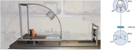
In order to estimate and characterize the actual stereo reconstruction capabilities of STC, an indoor Stereo Validation Setup (SVS) has been developed in laboratory. The SVS is a combination of optical and mechanical components that allows the indoor reproduction of the instrument observing conditions. The main components of the stereo validation setup are (Figure 1):
- a collimator lens (achromatic doublet with focal length of 1000 mm with a diameter of 80 mm) that collimates the light rays, coming from the target, at the infinite
- a motorized rotation stage which simulates the stereo angle of STC (RPV)
- a target positioned on the RPV rotation stage,
- a light source mounted over a curve rail system conceived to rotate together with the target support plate maintaining a constant lighting condition.
Everything is mounted over an optical bench making it easier the integration with the optical ground support equipment (OGSE), that has been used for the calibration of STC in the laboratories of Selex ES (the company in charge of the production and assembly of the camera).
The same object area is imaged first by the Forward looking channel and, after stage rotation, by the Backward looking channel. The indoor simulation of the spacecraft trajectory (for simplicity only the periherm is considered) is provided by two high precision motorized rotation stages (RPV).
Figure 1: Left image: The SVS. The halogen lamp is mounted on the first rotational stage where the target sample is positioned. A collimator (on the right side) completes the optical system permitting the use of STC indoor. Right image: In laboratory simulation of STC observing with “Forward channel” and “Backward channel” at periherm by means of the SVS. Two RPV rotate the STC FM and the target.
The SVS gives the important opportunity to investigate some of the aspects that could affect the surface reconstruction by providing a series of images acquired under different illumination angles, later compressed by different compression factors.
The variability of the illumination in the datasets is an important factor to be analysed in order to reach higher levels of accuracy
investigation. In particular the lamp holder, thanks to a curve rail system, allows the setting of different light incidence angles, i.e. several observing conditions. STC SVS light source (narrow-spot halogen lamp) has been mounted over the curve rail system conceived to rotate together with the target support plate, so maintaining a constant lighting during the acquisition (Figure 2). The support has been designed providing the same light incidence angle for both left and right (or forward and backward) images of stereo couples to reproduce some of the light incidence angles (10°, 30°, 50° and 70°) representing the Sun rays incidence angles to the Mercury surface when the spacecraft is at periherm (Re, et al., 2015) at different epochs.
Figure 2: The illumination setup maintains a constant illumination on the target.
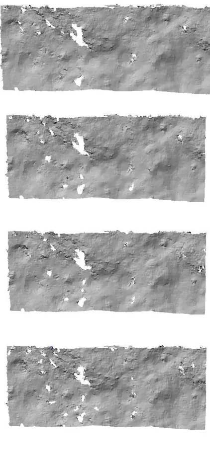
A set of images for both the samples under the four different incidence angles have been used for the generation of several DTMs (Figure 3). A series of white pins are visible on the image pairs set. The pins attached on the target surfaces allowed an easy, accurate and non-ambiguous identification of Ground Control Points (GCP) both in the images and in the reference DTM. The GCPs have been useful for the definition of the exterior orientation parameters (EO) by a bundle block adjustment procedure (Re et al. 2015).
a) b)
Figure 3. The images show the effect of the four different illumination conditions (from the top the 10° to the last 70° image on the bottom) both for Anorthosite (a) and Concrete
(b) samples.
4. THE COMPRESSION ALGORITHM
(lossless) compression and irreversible (lossy) compression. The algorithm is controlled by the parameter ibr, that can assume the values from 0 to 63. ibr = 0 means bit packing, ibr = 1 means lossless compression; an ibr value between 3 and 63 defines the actual compression ratio and bit rate, as follows:
Bit rate = ibr/16
Compression ratio = ADC_bits/(ibr/16)
where ADC_bits = 14 considering that 1 pixel for SIMBIOSYS is 14 bits.
The ibr values defining a lossy compression and considered in the investigation are the following:
ibr = 4 <=>0.25 bit/pixel<=> compression factor = 56 ibr = 8 <=> 0.5 bit/pixel <=> compression factor = 28 ibr=16 <=> 1 bit/pixel <=> compression factor = 14 ibr=32 <=> 2 bit/pixel <=> compression factor = 7 ibr=63 <=> 3.9375 bit/pixel <=> compression factor = 3.56
During the nominal mission most of the images (panchromatic ones) will be downlinked applying a compression factor of 7. The wavelet transformation (Mallat, 1989) is one of the most performing techniques for data compression uses. Using orthogonal or bi-orthogonal filters, this reversible transformation provides a set of local high and low frequency terms of the signal, which has the same dimension as the original data.
A new version of the Said-Pearlman hierarchical tree-coding algorithm (SPHT) has been implemented as real time compression strategy for the SIMBIO-SYS package, emphasizing the improvement in processing speed and the evolution of the compression performances. In the SPHT, a tree of descendants is associated to each element of the array. Each tree contains information on the same region of the image at increasing spatial frequencies. This new version of SPHT optimized for speed has compression performances which approach that of the arithmetically coded version. A specific procedure has been defined for spectral image cubes, which improves the distortion by more than a factor of 2 compared to a straightforward treatment as sets of 2-D images.
5. QUALITY OF COMPRESSED IMAGES VARYING
THE ILLUMINATION ANGLE
In image compression, the quality of a reconstructed image has been evaluated by two indicators: the peak signal-to-noise ratio (PSNR) that compares the original and compressed images (Netravali and Haskell,1995) and the Entropy (Kiefner and Hahn, 2000) that applies to a single image. These indicators provide information about how the pixel values change after compression, with PSNR taking the original image as reference. PSNR represents (Figure 4) the radiometric degradation of the reconstructed image as function of the Mean Square Error (MSE)
log / ;
MSE
where gij = grey valuesof the compressed image g’ij = grey valuesof the original image M,N= image dimensions
A= image bit depth
Figure 4: PSNR values as a function of ibr for 10° and 70° illumination angles
Entropy is defined by the following equation:
where L= 2^(n_bit-1); n_bit=14;
p= the probabilities of the different grey values by normalizing image intensity histogram
Figure 5 shows the plots of Entropy as a function of ibr for images acquired with 10° and 70° illumination angles.
Figure 5: Entropy values as a function of ibr for 10° and 70° illumination angles
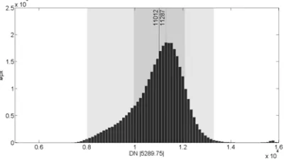
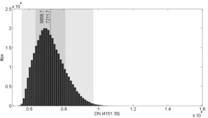
From the previous graphs (Figure 4 and 5), what emerges is that the PSNR curves are highest for the low entropy 70° images and the lowest, for the high entropy 10° images. In terms of dynamic range the 10° images are defined by 5289 DN with respect to 4151 DN for the 70° (see Figure 6).
Figure 6: Image histogram with mean (solid line) and median (dotted line) value of the DN. a) 10° image; b) 70° image.
This means the first ones are likely to have higher entropy and an expected lower compressibility. The image histogram, i.e. the statistical distribution of image pixels in terms of number of pixels at each DN is an useful tool for contrast enhancement. In the Figure 6, for the 10° images the Standard Deviation of DN is larger than that for the 70° images determining an higher overall contrast of the image.
6. ANALYSIS OF DTM ACCURACY AND
DEGRADATION
The effect of compression has been evaluated in terms of degradation of the vertical accuracy of the DTMs produced photogrammetrically (by the Dense Matcher software, see Re et al., 2012) by the lossy compressed stereo pairs. Likewise, the resampled to form a mesh of equidistant points on a XY grid. The high resolution laser scanner reconstruction of the sample target has a better vertical accuracy than the one provided by the stereo image reconstruction and has therefore been used as “true” data. The comparison between the stereo DTM and the reference DTM gave the confidence about the capability of the system to perform stereoscopic imaging. A detailed description of the DTM generation procedure for the rock samples and of the alignment of the DTM with the reference DTM is described in (Re et al. 2015). Two DTM quality parameter are derived from the comparison: the Root Mean Square Error (RMSE) computed as RMS of the absolute distance from the reference surface of each point in the generated DTM; the number of “good points”, i.e. of reliable matches provided by the matching process can also be evaluated. Table 1 shows the results obtained processing the original (not compressed) concrete images under different illumination angles.
Table 1: RMSE and number of “good points” in the DTM
To estimate the degradation of the DTM quality due to compression and illumination, the image pair of the Concrete sample (see Figure 3 b) has been processed for each ibr value and for both the lower (70°) and higher (10°) illumination angles. A DTM has been generated by matching the two images of the pair in all combinations of the compression ratio. The vertical accuracy (RMSE) of the DTMs and the number of “good points” are reported in the following tables, where the diagonal entries refer to the same compression factor applied to both images of a stereo pair:
Table 2-3: RMSE (mm) in elevation of the DTM for all combinations of compression factors in the image pair. Left:
10° image pair; Right: 70° image pair
4 8 16 32 63
4
178217 179387 171075 160966 156088 8
195847 193211 187684 184809 16
199038 195357 193735
32
222099 224204 220039 215158 213219 8
235530 234650 232524 231466 16
Table 4-5: Number of “good points” in the DTM for all combinations of compression factors in the image pair.
Left: 10° image pair; Right: 70° image pair
Tables 2-3 show that the increase of the RMSE with the compression is mild for low compression factors. Combining images with different compression factors (off diagonal values) the result is in most cases marginally better than the diagonal case with higher compression. Similar considerations apply to Table 4-5, perhaps with a lower decrease rate as compression grows. Interestingly, the comparison with Table 1 shows a general improvement in the number of good matches, except for the highest compression factor. Viceversa, the numbers in the off diagonal entries are always lower than both diagonal elements, i.e. a larger number of outliers can be expected mixing different compression factors.
Figure 7 shows the degradation of the Concrete DTM computed as percentage of the RMSE of the uncompressed images. Less than 10% in accuracy is lost up to a factor 14, with the max illumination angle very little affected with respect to the 70° images. Interestingly, the 10° images at the lowest compression factor produce a DTM more accurate (1%) than the corresponding one produced by the original images.
Probably, the smoothing effect of the compressor helps somehow the matching phase especially in the case of 10°images. The International Archives of the Photogrammetry, Remote Sensing and Spatial Information Sciences, Volume XLI-B4, 2016
Figure 7: Degradation of the Concrete DTM at various ibr values, computed as percentage of the RMSE of the
uncompressed original images (Table 1)
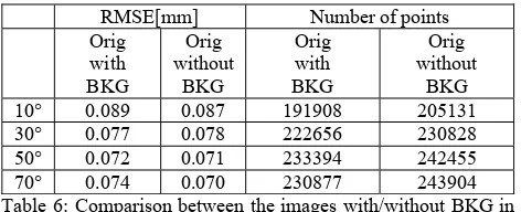
The sensor background noise is characterized by a not negligible pixel to pixel variability and some tests have been performed in order to evaluate how it affects the DTM generation after the compression process.
Comparing the not compressed images with the sensor background (BKG) included and the not compressed images (without BKG) as reported in the next Table 6, some considerations might be inferred.
RMSE[mm] Number of points
Orig with BKG
Orig without
BKG
Orig with BKG
Orig without
BKG
10° 0.089 0.087 191908 205131
30° 0.077 0.078 222656 230828
50° 0.072 0.071 233394 242455
70° 0.074 0.070 230877 243904
Table 6: Comparison between the images with/without BKG in terms of RMSE and Number of points
The results in terms of RMSE and number of points reconstructed, as function of the illumination angles, suggest that the processing of the images without background provides better results especially in correspondence of the higher illumination angle (70°). The interpixel variability is quite high (+60/-60 DN) and its influence suggests to have larger impact on the point measurements when the 70° images are considered. There is also an overall improvement of the number of matched points for all the illumination angles when the images are processed without the BKG.
Since the mission nominal value of the ibr will be 32 and once the images are on ground (compressed) it is possible to choose the better strategy to manage the BKG information, as the subtraction of the BKG compressed or not compressed from the images. A test has been performed to evaluate the best strategy: applying the nominal compression factor and for each illumination angle by comparing the compressed images with subtraction of the:
- background compressed with ibr 32 (ICB) - background not compressed (ICUB)
Figure 8: Top: graph of RMSE for both the concrete and the anorthosite samples with and without compressed background, at various illumination angles. Bottom: graph of the number of
“good points” in the same cases as above.
Figure 8 shows that in the case of the Anorthosite the RMSE is higher and decreases with increasing illumination angles. The best value in terms of accuracy is obtained at 70° of illumination but the range between the maximum value and the minimum is only 7 microns (both for ICB and ICUB images). In the case of the Concrete, a minimum is reached at 50° of illumination and the overall range reaches 15 microns. Accordingly, the number of matched points is maximum for the Concrete at 50° while the Anorthosite has a maximum at 70°.
The different morphological and chromatic characteristics of the stones could explain these different trends. The Concrete provides best results both in terms of RMSE and of completeness of the models with respect to the Anorthosite case.
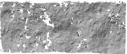
Looking at the colour error maps (Figure 9 and 10), especially for the Concrete sample, the completeness of the 50° acquired images it is better than the 10° ones. The colour error maps show that the higher errors in sign occur where the surface roughness is higher and by a comparison with the original images, the higher spikes are related to points having high reflectivity.
Figure 9. Colour coded error map of the Concrete sample DTM for 10° (top) and 50° (bottom) illumination angle
Figure 10. Colour coded error map of the Anorthosite sample DTM for 10° (top) and 50° (bottom) illumination angle
The presence of spot reflections on the Anorthosite surface (from the glue used to attach the pins and from tiny crystals) produces saturated pixels converted in holes in the DTMs. Furthermore the shadows created by the surface roughness (the surface curvature is higher with respect to the Concrete as shown in the Figure 11 c) might check the number of good matches.
a) b)
c)
Figure 11: a) cross section on Anorthosite DTM; b) cross
Figure 12 shows the degradation of the DTM varying the ibr from a qualitative point of view: the shaded relief image computed from the DTM provides a visual impression of which features are and are not reconstructed and what sort of artefacts and noise are present within the DTM. Starting from the DTM obtained with the original images and increasing the compression factor from ibr 63 up to ibr 4, we can notice how the noise in the reconstruction increases together with the number of the holes. Also looking at the disparity maps in Figure 13 and 14 the holes in correspondence of the mismatches (points of low correlation threshold/points not matched) are clear with the increasing of the compression factor and particularly localized around areas of reflectivity of the surface or areas of shadows that make the texture homogenous and lacking of radiometric contrasts good for matching the homologous.
Figure 12: Concrete shaded relief DTMs obtained from different set of compressed images. From top to bottom:
compressed images at 63, 32, 16, 8 and 4 ibr
Figure 13: From top left to bottom right: crop of the image obtained at 70° of incidence angle,
laser disparity map, uncompressed images disparity map, disparity map at ibr 63, 32, and16 ibr respectively.
Figure 14: From top left to bottom right: crop of the image obtained at 10° of incidence angle,
laser disparity map, uncompressed images disparity map, disparity map at ibr 63, 32, and16 ibr respectively.
An interesting indicator of the matching performance is the statistical distribution of the Normalized Cross Correlation (NCC) values varying the illumination angles. Figure 15 shows such histograms for the ICB images. The NCC values are on average higher for the 50° and 70° images than the 10° images, where the histogram is flattened (lower values of the statistics and a lower number of matched points involved).
a)
b)
Figure 15: Histograms of NCC values with mean (red solid line) and median value (red dotted line). a) Illumination angles 10° (left) and 30° (right); b) Illumination angles 50° (left) and 70° (right)
7. DEGRADATION OF THE IMAGE MEASUREMENTS
DUE TO THE IMAGE COMPRESSION AND THE ILLUMINATION ANGLE
In order to highlight the dependence of the image measurement accuracy by the compression, the errors on the disparity maps have been considered, using the images compressed without background compression (ICB). Besides the ibr value, also the illumination angle has been varied in the tests.
With a threshold of 0.9 for the Normalized cross-correlation coefficient (NCC) imposed in the matching process, the disparity map for each model has been generated. Since epipolar resampling has been performed, only the parallax along the y-axis has been considered.
In order to compute the parallax error, the laser coordinates have been projected on both images, producing a “true” disparity map (disregarding the EO errors). Disparity error maps can therefore be generated, for both the original and the compressed images, The International Archives of the Photogrammetry, Remote Sensing and Spatial Information Sciences, Volume XLI-B4, 2016
by computing the discrepancies with respect to the “true” disparity map.
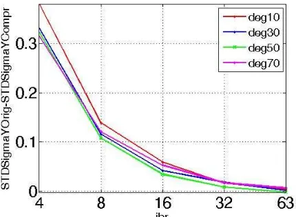
Figure 16: Standard deviations of the differences (pix) between the disparity error map of the original images and the disparity error map of the compressed images for different illumination angles and image compression
Figure 16 shows the Standard Deviations of the differences (in pixel) between the disparity error map of the original images and the disparity error map of the compressed images, plotted for different illumination angles and image compression.
As can be seen, the degradation that can occur to the measurement accuracy on the image plane after the compression at the nominal ibr 32 is much lower than 0.1 pixel, achieving the maximum value at the ibr 4.
It is interesting to note that the degradation is very similar at different illumination angles at higher ibr. It is possible to appreciate a difference between 10° and other angles for ibr lower than 16.
CONCLUSIONS
The flexibility in the operations and in the observing strategy of STC, combined with different compression ratios of the acquired frames, gives the possibility to optimize the data volume allocated.
In this work we have seen that the DTM degradation due to higher compression ratios is not so important, that might be compensated by an higher number of images of the same regions or applying a different observing strategy.
For what is concerning the compression effect, some aspects have to be taken in account to choose the best configuration, as the dynamic range of the image and the surface characteristics of the acquired features.
Another important parameter to take into account, in the discussion of the DTM degradation, is the illumination conditions within a set of stereo images. This investigation suggests it might be relevant in the DTM generation both in terms of accuracy and completeness. Reduced quality is demonstrated at the low incidence angle of 10° with respect to higher values. Most likely it is due to a large number of shadows, for higher
For future work we plan to make tests with a real scene (for example MDIS Messenger images) superimposed by the detector “noise” (the dark fraction (DSNU) acquired in laboratory) in order to check the pixel to pixel sensor variability influence on the final results.
This investigation on the influence of compression on space-image provides relevant information on the STC Mercury DTM expected production quality and could be useful for planning stereo observations.
REFERENCES
Cremonese, G., et al, 2009. “The stereo camera on the BepiColombo ESA/JAXA mission: a novel approach”, Advances in Geosciences, Vol. 15, pp. 305-322
Da Deppo V., et al. 2010,“Optical design of the single-detector planetary stereo camera for the BepiColombo European Space Agency mission to Mercury”, App. Opt., vol. 49(15), pp. 2910-2919
Kiefner, M., & Hahn, M. (2000). Image compression versus matching accuracy. International Archives of Photogrammetry and Remote Sensing, 33(B2; PART 2), 316-323.
Langevin Y, Forni O, 2000.” Image and spectral image compression for four experiments on the ROSETTA and Mars Express missions of ESA” Proc. SPIE 4115, Applications of Digital Image Processing XXIII, (28 December 2000); doi: 10.1117/12.411561”
Li, H., Yuan, X., Lam, K.W.K., 2002. Effects of JPEG Compression on the Accuracy of Photogrammetric Point Determination. Photogram metric Engineering & Remote Sensing, Vol. 68 No. 8, pp. 847 – 853.
Netravali, A.N. and Haskell, B.G.1995. Digital Pictures: Representation, Compression, and Standard, 2nd ed., Plenum, New York.
Mallat S., 1989: “A theory for multiresolution signal decomposition : the wavelet representation”, IEEE Trans. Patt. Anal. Machine Intell. 11, pp. 674-693, 1989
Re C., Roncella R., Forlani G., Cremonese G., Naletto G. , 2012. “Evaluation of area-based image matching applied to DTM generation with Hirise images”, International Archives of Photogrammetry, Remote Sensing and Spatial Information Sciences, Vol XXXIX, Part IV/7
Re C, et al., 2015. “DTM generation from STC-SIMBIO-SYS images” Proc. SPIE 9528, Videometrics, Range Imaging, and Applications XIII, 95280P (June 21, 2015); doi:10.1117/12.2184745
Robinson, C., Montgomery, B. and Fraser, C., 1995. The effects of image compression on automated DTM generation. In: Photogrammetric Week ’95. Wichmann Verlag, Heidelberg, pp. 255-262.