EVALUATING UNMANNED AERIAL PLATFORMS FOR CULTURAL HERITAGE
LARGE SCALE MAPPING
A. Georgopoulos*, Ch. Oikonomou, E. Adamopoulos, E.K. Stathopoulou
Laboratory of Photogrammetry, School of Rural & Surveying Engineering National Technical University of Athens, Greece
[email protected], [email protected], [email protected], [email protected]
Commission V, WG V/2
KEY WORDS: UAS, large scale mapping, structure from motion, dense matching, orthophotos
ABSTRACT:
When it comes to large scale mapping of limited areas especially for cultural heritage sites, things become critical. Optical and non-optical sensors are developed to such sizes and weights that can be lifted by such platforms, like e.g. LiDAR units. At the same time there is an increase in emphasis on solutions that enable users to get access to 3D information faster and cheaper. Considering the multitude of platforms, cameras and the advancement of algorithms in conjunction with the increase of available computing power this challenge should and indeed is further investigated. In this paper a short review of the UAS technologies today is attempted. A discussion follows as to their applicability and advantages, depending on their specifications, which vary immensely. The on-board cameras available are also compared and evaluated for large scale mapping. Furthermore a thorough analysis, review and experimentation with different software implementations of Structure from Motion and Multiple View Stereo algorithms, able to process such dense and mostly unordered sequence of digital images is also conducted and presented. As test data set, we use a rich optical and thermal data set from both fixed wing and multi-rotor platforms over an archaeological excavation with adverse height variations and using different cameras. Dense 3D point clouds, digital terrain models and orthophotos have been produced and evaluated for their radiometric as well as metric qualities
1. INTRODUCTION
During the recent years the use of unmanned aerial systems (UAS) of any kind for large scale mapping and in the geospatial domain in general has experienced an incredible boom (Eltner & Schneider, 2015). Over a short period of time a plethora of platform types and, most importantly a multitude of cameras and other sensors have been made available and are being implemented with different and often uncontrollable results. Sometimes their combinations also challenge the implementation of conventional aerial photography for certain applications (Colomina & Molina 2014). Legislation is another critical issue when unmanned aerial platforms are involved, as it varies a lot from country to country, if rules apply at all. Gradually, however, most of the countries pass pertinent laws governing the flight and use of these UAS. A short review of the current situation is initially attempted, in order to enlighten potential users of the applicability of such systems.
On the other hand, automated or semi-automated photogrammetric software implementing Structure from Motion (SfM) and Multiview Stereo (MVS) algorithms have become extremely popular making photogrammetry, a rather obscure science up to now a commonly used tool among the non-expert community. Several pieces of automated software implementing SfM/MVS algorithms coming with user-friendly graphical interfaces are already available, both commercial and freeware. In the literature a variety of several comparison reports for such algorithms can be found mainly using benchmark images (Seitz et al. 2006, Remondino et al. 2014). This “automation without deep knowledge” situation has many pitfalls, as uncontrollable processing may easily lead to nice looking, but completely and most severely slightly wrong products. Consequently, their implementation should be done with caution and always under
the supervision of an expert in evaluating and assessing photogrammetric products. These two facts are the main motivation behind this project, whose first results were reported in Oikonomou et al. (2015) and which aims to investigate the applicability of UAS and the images that these aircraft are capable of acquiring in combination with automated SfM/MVS software. Relative recent literature includes studies about the usability of UASs in cultural heritage mapping or surface measurement (Sauerbeier et al. 2010; Remondino et al. 2011; Neitzel et al., 2011), using different UAS acquisition platforms (Lo Brutto et al. 2014), combination of terrestrial and aerial UAS data for 3D reconstruction evaluation (Koutsoudis et al. 2014) or assessments on UAS data dense matching (Haala & Rothermel, 2012). To realize an objective evaluation of the generated point clouds, DSMs or orthophotos, ground truth data is needed, such as LiDAR data or evenly distributed ground control points (GCPs) measured with GNSS.
The current study focuses on a short review on UAS platforms and cameras, using some data scenarios of a rather limited cultural heritage site to assess the performance of state of the art algorithm SfM/MVS implementations. Several experiments are conducted in order to evaluate systems, sensors and software based on the final results i.e., DSMs and large scale orthophotos in this case. Although the range is not yet complete, it is believed that it presents an overview of the available systems, software and their usability.
In section 2 of this paper a short review of the Unmanned Aerial Systems (UAS) is presented along with reference to payloads and legislation issues. Τhe data sets used for the practical experimentation are described in section 3. In section 4 the algorithm implementations are briefly described. Description of the processing stage and the presentation of results and their evaluation follows in section 5 and finally in section 6 some concluding remarks are attempted.
2. UAS TECHNOLOGY larger areas, as for archaeological excavation sites –because they pose arduousness to manoeuvre, usually require bigger flying heights for safety reasons and elongated areas to lift off/land. They are generally more inexpensive to maintain. The second category refers on multi-rotor UAS, more commonly used in CH large scale mapping than fixed-wing due to their enhanced manoeuvrability (Lo Brutto et al. 2014). They are stable, having the ability to move vertically and hover. differences. They can also reach the object of interest from close distance with the purpose of exporting imaging derivatives that could not be produced by traditional aerial or terrestrial photogrammetry e.g. top view-orthophotos.
On the other hand, rotary wing UAS involve greater mechanical and electronic complexity which translates into generally more complex maintenance, repair work and time consumption. This type of vehicles is able to carry smaller payload, affecting the number, size and weight of sensors which can be mounted on the system, especially for smaller or lower cost categories.
Finally, because of their lower speed and the shortest flight duration (10-25 min), the operator will require many extra flights to cover larger areas, leading to another increase in time and operational costs. For CH applications, finding the appropriate balance between overall cost, body frame type and weight, sensing payload precision and accuracy for given standards is challenging (Colomina, Molina 2014). In the following sections, a short review and comparison between state-of-the-art sensors for UAS commonly used for CH large scale mapping is presented.
2.2 Optical cameras
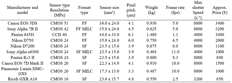
Visible band sensors are widely used for CH photogrammetric applications using UAS, mainly aiming for orthophotos, orthomosaics, 3D models, and surface and elevation models generation. Some of the important parameters to take into consideration while in the project planning phase are: the sensor type and resolution, the pixel size, the frame rate, the shutter speed, the focal length to be used as well as the weight of the camera/lens system. The most commonly used types of optical sensors used are CCD and CMOS DSLR cameras, while mirrorless cameras are becoming increasingly popular, mainly because of their small weight. Table 1 summarizes the latest and most representative optical cameras suitable for CH mapping with UAS.
The use of high resolution and small pixel size optical sensors allows for the generation of high precision photogrammetric products, though built-in optical cameras in fixed winged UAS, are usually of smaller resolution and usually of unspecified precision, so that these systems represent a cheaper solution for low-precision applications.
Table 1: Common and/or representative optical cameras suitable for UAS
2.3 Thermal cameras
In the recent years the miniaturization of infrared sensors has enabled their usage in unmanned platforms (Colomina, Molina 2014). This integration is ideal for real time surveillance, monitoring, risk management, calculation and improvement of the energy efficiency of buildings etc. Moreover, acquisition and further processing of thermal images may allow precise temperature measurements per pixel, or even producing “thermal” 3D models with them. Regarding CH applications, these imaging derivatives can be useful in revealing previously undocumented architectural features and non-destructive
building diagnostics including moisture or deterioration inspections. Latest near infrared imaging technologies include uncooled micro bolometers as thermal sensors. These are low-cost, lightweight sensors, but their analysis is significantly lower than that of the visible spectrum sensors, mostly 320 x 256 pixels, 384 x 288, or 640 x 512 (up to the most expensive models) and also are less sensitive than cooled thermal and photon detector imagers with increased noise factor. Table 2 summarizes the latest commercially available thermal cameras suitable for CH UAS mapping. Upon choosing a thermal camera, the most important factors are pixel size, spectral range and thermal sensitivity.
Manufacturer and Table 2: Common and/or representative thermal cameras suitable for UAS
2.4. Flight Rules
The EU has not issued a directive regarding the UAS or any restrictions on their use, but the European Data Protection Supervisor has expressed in a text without legal force his opinion on the matter. In this text, the social and economic benefits from the use of UAS are highlighted, stressing the need to harmonize the aviation related UAS policies of the Member States' safety, referring to liability and public security and noted that the proliferation of UAS can be achieved by ensuring compliance in matters concerning personal data, privacy and security. This text does not set out any technical rules, yet citations are made to other regulations of the EU or of the Member States. In general, those of the other EU states that have issued instructions regarding the UAS are consistent with each other. Namely, in most EU countries the flight of a UAS is prohibited unless it is inside the operator’s field of view or at a height of below 250-400 feet, at long distance from people or residential areas and outside military installations or airports. Concerning CH applications, in most cases specific permission is required to use UAS inside or indeed above archaeological sites.
In the USA, the Federal Aviation Administration on a memorandum makes clear that the use of proprietary UAS for news gathering for the media or for other business purposes requires permission from the Federation, while the use of UAS for recreational purposes does not require permission. Hence, even in the USA federal authorities do not adopt technical rules restricting the use of such systems. These restrictions are enacted at state level and in some cases are strict or almost non-existent. To operate UAS commercially in South Africa, the operators need to hold 5 certificates, including registration of all UAS used for commercial purposes. Operators must meet the legal requirements set out by the SACAA (Civil Aviation Authority) and are audited regularly for compliance. In Oceania and Asia similar licenses and permissions are required, while all of the above airworthiness certificates are issued for UAS by the respective aviation authority. Canada and India are about to issue new directives due to the large number of incidents including UAS.
3. DESCRIPTION OF THE DATA SET
The evaluation and comparison of the photogrammetric products, produced by different algorithm implementations were based on data sets available from previous projects. In particular, the data sets used for this study were acquired during the Erasmus Intensive Programme HERICT2013, an international Summer School organized by the Laboratory of Photogrammetry of NTUA for the documentation support of the archaeological excavation in Vassilika settlement in the
archaeological site of Kymisala in Rhodes (Acevedo et al. 2013). The Vassilika settlement lies within the wider archaeological site and it actually is the ruins of an organized urban network covering an area of approximately 200x250m with some 10m of height differences.
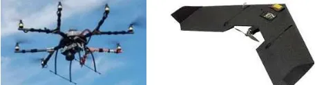
Careful flight planning was crucial for the correct positioning of the pre-marked GCP’s. For both UAS employed flight planning was carried out using proprietary software which enabled introduction of the parameters based on Google Earth. After each flight and image acquisition, the data was downloaded and checked for their integrity. The data acquisition process also included the collection, archiving and storing of all necessary metadata. The UAV’s employed (Figure 1) were the Swinglet fixed wing airplane by Sensefly and an octocopter developed by the Hafen City University. For the needs of the Erasmus IP also a Dunford Flying Machine kite and smaller UAV with a built-in camera for some experimental flights were also employed. However for this project only the data from the fixed wing and the octocopter will be used.
Figure 1: The UAV’s used for acquiring the digital image data
The octocopter is a lightweight multi-rotor system with 8 rotors and has a maximum payload of approximately 1kg. The maximum duration of the flight is around 15 minutes and a compact digital camera Samsung NX1000 was integrated for the image capturing. This camera has a 23.5x15.7mm2 sensor with 20MP resolution and a pixel pitch of 4,3μm The Swinglet Cam manufactured by Sensefly (https://www.sensefly.com/ drones/swinglet-cam.html), is an electrically-powered fixed wing platform and is approximately 0.5kg heavy. It is so lightweight that the user can launch it by hand and let it land on almost any surface without using any supporting system, such as a parachute. Its small impact energy also reduces significantly the risks of third-party collision damage. Two cameras were available for this UAS. A Canon Ixus 220HS compact camera recording 12.1 MP (sensor size 6.14x4.55mm2 and pixel pitch of 1.5μm) optical images and a Canon PowerShot ELPH300HS compact camera (sensor size 6.14x4.55mm2 and pixel pitch of 1.5μm) capable of recording infrared images of 12.1MP. The mission planning with both sensors has been automated for the application using e-motion software.
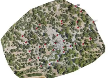
Ground control points were measured using GNSS and the Real Time Kinematic method (RTK) with an accuracy of 2-3 cm.
They were signalized with a 20cm2 black and white checkerboard pattern and were distributed in order to cover the entire area in the most effective possible way. Particularly, 15 points were used as control points and another 15 as check points. For this project several processing strategies were considered. After careful examination it was decided to process the data from each UAS separately and in addition to process the data from the two flights, i.e. flying height of 60m and 90m of the Swinglet together. In Table 3 an overview of all the examined scenarios is presented regarding the acquisition equipment, the flying height and ground sampling distance.
Figure 2: Area of interest and distribution of the Ground Control Points
The images captured from the octocopter form a more stable block configuration with great overlaps among them, while the acquisition points using the fixed wing platform are more random. This resulted in higher overlap percentages providing, thus, a more stable solution. Moreover the camera used in the octocopter was of superior resolution and significantly greater pixel pitch and the results are expected to be better. In Figure 3 the camera stations, i.e. the image distribution is presented for each scenario.
Figure 3: Camera stations for Scenario 1 (above), 2 and 3 (below)
4. METHODOLOGY
It was decided to use contemporary automated photogrammetric and computer vision algorithms for processing the data sets. This implies the implementation of Structure-from-Motion (SfM) and Dense Image Matching for orienting the images and producing 3D information about the object. Structure from Motion approaches (SfM) (Szeliski, 2010; R. Hartley & Zisserman, 2003) in computer vision are image based techniques using epipolar geometry concepts to calculate the
camera path and reconstruct the object scene in 3D without any prior knowledge. Their ability of handling large datasets of unordered images has made them popular among the professional and research communities. They rely on accurate detection, description and matching of feature points mostly using SIFT-like algorithms (Lowe 1999) to calculate the relative camera positions resulting to a sparse 3D point cloud. This point cloud is thereafter densified using MVS (multi-view stereo) algorithms by reconstructing almost every pixel (Haala, 2013) and finally a complete textured point cloud can be delivered. Further outcomes such as triangulated meshes, DSMs or orthophotos can also be produced. Various software implementations of the aforementioned algorithms are currently available, commercial, freeware or open source. In this study Agisoft PhotoScan, Pix4Dmapper and SURE were tested. Agisoft PhotoScan and Pix4Dmapper are commercial packages, which integrate the complete image-based reconstruction process from image orientation to triangulated mesh generation. They also allow for orthophoto creation and other editing complementary tools. Little information is available about the proprietary algorithms implemented. SURE (photogrammetric SUrface REconstruction) is a commercial, yet free for research purposes, MVS solution that uses tSGM for the creation of the dense point cloud (Haala and Rothermel, 2012; Rothermel et al. 2012). It allows high parametrization and thus flexibility by the user and can deliver dense point clouds, triangulated meshes and true orthophotos given the camera orientations. In this study, as opposed to Oikonomou et al. (2015), VisualSfM, a freeware software, was excluded, as GCPs are not considered in the same way while performing bundle adjustment. The datasets were thoroughly processed using the above mentioned software and the resulting point clouds, orthophotos were compared for their qualities.
5. DATA PROCESSING AND EVALUATION Data processing includes camera pose estimation, point cloud densification and orthophoto generation. The camera Scenario Platform Camera Type # of images Resolution Flying Height (m) GSD (m)
1 Octocopter Sony NX1000 RGB 237 5472*3648 35 0.01
2 Swinglet Cam Canon IXUS 220HS
RGB 83 4000*3000 60 & 90 0.02 & 0.03
3 Swinglet Cam Canon
PowerShot ELPH 300HS
NIR 96 4000*3000 90 0.03
Table 3: Overview of the datasets
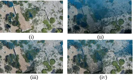
orientations were calculated using the two commercial software applications available, i.e. Agisoft PhotoScan and Pix4Dmapper as in (Oikonomou et al., 2015). Given the orientation parameters from those two, SURE is then used for dense image matching and orthophoto production as well. Hence four different processing methods were implemented as far as the point cloud production is concerned. Firstly the two pieces of software on their own and secondly introducing the orientation, i.e. alignment, results of PhotoScan and Pix4D into SURE to perform the dense image matching. The differences of this processing for Scenario 2 are presented in Figure 4.
The three scenarios described in section 3 were used to evaluate the performance of the aforementioned image-based reconstruction algorithms and thus the quality of the acquired data with the different platforms, based on the metric and visual quality of the results. No LiDAR data were available as reference dataset and for this reason, yet Ground Control Points were used as ground truth data.
(i) (ii)
(iii) (iv)
Figure 4: Detail of the dense cloud of Scenario 2 processed with Agisoft PhotoScan (i), Pix4Dmapper (ii), SURE (Agisoft)
(iii) and SURE (Pix4Dmapper) (iv) respectively
A first evaluation of the performance of the image-based reconstruction algorithms is conducted by assessing the alignment results. In scenarios 2 and 3, Pix4Dmapper produces 25% more points in the sparse cloud in average than PhotoScan (Table 4). Only in the first scenario the results are contradictory as PhotoScan triangulates almost 2.2M points, whereas Pix4Dmapper 1.2M points. In both cases, this stage is successfully performed, yet few images could not be aligned in
scenarios 2 and 3. It is stressed that for all cases the same PC configuration was used, in order for the results to be comparable.
S
ce
n
a
ri
o # Points Time (mins)
PhotoScan Pix4D PhotoScan Pix4D
1 2.2 M 1.2M 120 19
2 162K 204K 8 7
3 201K 245K 16 8
Table 4: Sparse point clouds generated using the same PC configuration
In Table 5 the RMS errors of the ground control and check points for all scenarios are shown since they constitute reliable indicators for assessing the aerial triangulation and alignment accuracy. As shown, the results are of greater accuracy for Pix4Dmapper. In the third scenario, where NIR images were processed the results are quite similar. However, both solutions present acceptable accuracy for the target scale of the final product.
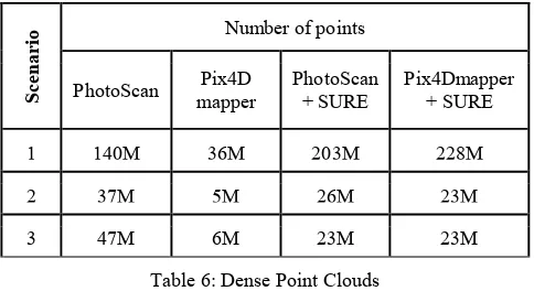
Regarding the dense 3D point cloud results, it is observedthat PhotoScan generates a larger number of point correspondences between the images. Indeed, PhotoScan has produced almost 140M points in the first scenario, almost four times more points than the corresponding solution in Pix4Dmapper. Using the image orientations coming from PhotoScan and Pix4Dmapper as input to SURE, a very dense point cloud is generated for scenario 1, while for scenarios 2 and 3 the resulting point clouds are smaller than those coming from PhotoScan densification, but still larger than those of Pix4Dmapper (Table 6). In all cases, it is noted that the algorithms perform better when (a) the imagery is strongly overlapping; (b) the camera moves in a relatively stable trajectory and (c) the images are of good quality.
S
ce
n
a
ri
o PhotoScan Pix4Dmapper
Control points Check points Control points Check points
RMSXY RMSZ RMSXY RMSZ RMSXY RMSZ RMS XY RMSZ
1 0.030 0.019 0.069 0.086 0.014 0.008 0.031 0.028
2 0.063 0.060 0.056 0.064 0.023 0.019 0.027 0.023
3 0.023 0.016 0.028 0.035 0.016 0.025 0.025 0.025
Table 5: Summary of RMS errors of the control points and the check points in PhotoScan and Pix4Dmapper (in m)
Dense point clouds resulting from Pix4Dmapper present large gaps in vegetation areas, however the point density increases in areas of rock and soil. On the other hand, the point clouds resulting from PhotoScan have fewer gaps and describe better the vegetation areas, giving a more realistic representation of the area of interest. SURE dense point cloud is detailed enough and noiseless for scenario 1, yet some gaps and noise in the vegetation areas are observed in scenarios 2 and 3, however they are less noticeable when the Agisoft PhotoScan image alignment is used as input (Figure 4).
Digital Surface Models arising from more dense point clouds offer great detail of the objects and precise edges, significantly improving the metric and visual quality of the products. The DSMs generated from Pix4Dmapper are quite smooth,
especially in the areas where the dense cloud is sparser, without losing in metric accuracy (2-4cm), taking into consideration the measured absolute vertical differences between the DSM and the check points. SURE DSM models are of similar quality, yet the results differ depending on the orientation input and thus the dense cloud produced. As expected, the greatest errors appear for all algorithms in scenario 2, which has the wildest image spatial distribution. The combination of Pix4Dmapper and SURE gives inferior results, which are not considered as representative as they occur just in this scenario. Here the lack of information produces gaps and mislead interpolation. In Table 7 the absolute vertical differences between the DMS elevations and the check points’ measured height are presented for all software solutions. These results are refined in the sense that, in areas where the software was unable to match satisfactory number of points, i.e. due to vegetation coverage, the check points in those areas were not taken into account. In all cases, however, more than 6 check points were used. In order to assess the metric quality of the derived orthophotos, a number of distances between ground control points and the corresponding ones in the orthophotos were measured. These measurements were performed manually and hence include the estimation errors of the operator. On the other hand, the measurements in the DSM are automatically calculated. These results are presented in Table 8.
Scenario 1 Scenario 2 Scenario 3
Software PhotoSca n
Pix4Dmapper PhotoScan Pix4Dmapper PhotoScan Pix4Dmapper
Mean absolute
vertical diff (mm) 23±15 19±15 68±47 29±28 27±24 36±28
Software PhotoSca n+ SURE
Pix4Dmapper +SURE
PhotoScan +SURE
Pix4Dmapper +SURE
PhotoScan+ SURE
Pix4Dmapper +SURE
Mean absolute
vertical diff (mm) 28±17 27±19 64±45 * 37±13 48±28
Table 7: Mean absolute vertical differences between check points and the Digital Surface Models and their standard deviation * In this case the results are not representative as already explained
Scenario 1 Scenario 2 Scenario 3
Software PhotoScan Pix4D PhotoScan Pix4D PhotoScan Pix4D Mean distance
difference (mm) 30±19 26±19 54±20 27±15 29±12 26±18
Software PhotoScan +SURE
Pix4D +SURE
PhotoScan +SURE
Pix4D +SURE
PhotoScan+ SURE
Pix4D +SURE
Mean distance
difference (mm) 29±19 22±17 35±14 40±18 28±11 36±19
Table 8: Mean distance differences between check points and on the orthophotos with their standard deviation
The results have shown that scenario 1 has produced better quality 3D models and orthophotos, mainly due to the more complete and evenly distributed image acquisition positions
(Figure 3). Indeed, for this dataset SURE outperforms the other two software solutions in terms of true orthophoto refinement. Less occlusions and similar defects like double images are
S
ce
n
a
ri
o Number of points
PhotoScan Pix4D mapper
PhotoScan + SURE
Pix4Dmapper + SURE
1 140M 36M 203M 228M
2 37M 5M 26M 23M
3 47M 6M 23M 23M
Table 6: Dense Point Clouds
observed (Figures 5 and 6). The radiometric quality is better without blurry areas and the colours are sharper, especially in the areas where drastic height differences occur and break lines would be otherwise needed.
Figure 5: Orthophotos produced by Agisoft (left) and Pix4D (right) for Scenario 1
Figure 6: Orthophotos produced by SURE+Agisoft and SURE+Pix4D for Scenario 1
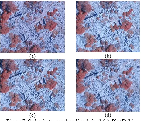
However, the geometric quality is similar in all four software combinations. On the other hand, for scenarios 2 and 3 the results are inferior (Figure 7). They are noisier irrespective of the software combination, obviously because of the irregular camera positions, which inevitably result to lack of information in the DSM and to lower overlap percentages. It should also be remembered that the ground sampling distance for Scenarios 2 and 3 was drastically less favourable.
(a) (b)
(c) (d)
Figure 7: Orthophotos produced by Agisoft (a), Pix4D (b), Agisoft+SURE (c), Pix4D+SURE (d) for Scenario 3
Computational time, as expected, is directly proportional to the size of the dataset and the image resolution. Thus, the first scenario consisting of more images and of higher resolution required more time than the other two for the complete process in both PhotoScan and Pix4Dmapper. It is ascertained that, apart from the second scenario, data processing is generally quicker in Pix4Dmapper. It was also remarked that in the stage of point cloud densification, PhotoScan requires almost double computation time than Pix4Dmapper, whereas in the stage of
DSM and orthophoto generation the opposite relation was observed.
Scenario Pix4Dmapper PhotoScan
Processing Time (hrs)
1 3.3 7.2
2 1 0.7
3 0.8 1.4
Hardware
CPU: Intel Core(TM) i7-4790 CPU @ 3.60GHz
RAM: 32GB
GPU: NVIDIA GeForce GTX 750 Ti
Table 9: Summary of the total processing time
6. CONCLUDING REMARKS
The results of UAS imagery for mapping strongly depends on the chosen platform. More stable flight trajectories mean dense overlaps and thus more complete point clouds, with no lack of information, as it was obvious with the images from the octocopter in this project. Hence, multi-rotor platforms are more suited for large scale mapping than fixed wing platforms which are more effective in mapping larger areas in shorter times. Concerning the software used, it is very important for the user to deeply understand the algorithms implemented and the required parameters, as they have proved to be very critical for the quality of the results. Hence this parametrization is a valuable tools for expert users, but extremely complex for non-experts who prefer fully automated fit-it-all solutions, leading thus to uncontrolled results. However, automation has enabled everyday users to produce qualitative and accurate results, depriving them at the same time of the necessary control on the procedures. For the project described, however, quite satisfactory results were derived with all algorithms implemented. The optimistic outlook is that with the constant evolvement of the computer vision techniques the future is really promising. All in all, UAV mapping is already widespread and constitutes a solution in a wide range of applications, especially in cultural heritage documentation.
ACKNOWLEDGEMENTS
This research has been made for the research project “State -of-the-art mapping technologies for Public Work Studies and Environmental Impact Assessment Studies” (SUM). For the Greek side SUM project was co-funded by the EU (European Regional Development Fund/ERDF) and the General Secretariat for Research and Technology (GSRT) under the framework of the Operational Programme "Competitiveness and Entrepreneurship", "Greece-Israel Bilateral R&T Cooperation 2013-2015". In addition this project has also received partial support from the European Union’s Seventh Framework Programme for research, technological development and demonstration under grant agreement no 608013, titled “ITN -DCH: Initial Training Network for Digital Cultural Heritage: Projecting our Past to the Future.” The data used were granted from the coordinator and the participants of the Intensive Programme IP Erasmus HERICT organized by the Laboratory of Photogrammetry of National Technical University of Athens.
The authors sincerely thank Mr. Konrad Wenzel for his support and advice regarding SURE.
REFERENCES
Acevedo - Pardo, C., Farjas, M., Georgopoulos, A., Mielczarek, M., Parenti, R., Parseliunas, E., Schramm, T., Skarlatos, D., Stefanakis,E., Tapinaki, S., Tucci, G., Zazo, A. and a team of 40 students, 2013. Experiences gained from the erasmus intensive programme HERICT 2013. ICERI2013 Proceedings, 4424-4431.
Colomina, I., Molina, P., 2014. Unmanned aerial systems for photogrammetry and remote sensing: A review, ISPRS Journal of Photogrammetry and Remote Sensing 92 (2014) p. 79-97.
Deseilligny, M. P., & Clery, I., 2011. Apero, an open source bundle adjustment software for automatic calibration and orientation of set of images. ISPRS-International Archives of the Photogrammetry, Remote Sensing and Spatial Information Sciences, 38, 5.
Eisenbeiss, H., 2009. UAV Photogrammetry, Doctoral Dissertation, ETH Zurich.
Eltner, A. and Schneider, D., 2015. Analysis of Different Methods for 3D Reconstruction of Natural Surfaces from Parallel‐ Axes UAV Images. The Photogrammetric Record, 30(151), pp.279-299.
Fregonese, L., Achille, C., Adami, A., Chiarini, S., Cremonesi, S., Fassi, F., Taffurelli L., 2015. UAV-Based Photogrammetry and Integrated Technologies for Architectural Applications— Methodological Strategies for the After-Quake Survey of Vertical Structures in Mantua (Italy), Sensors 2015, 15, 15520-15539, ISSN 1424-8220,
Furukawa, Y., Ponce, J., 2010. Accurate, dense, and robust multiview stereopsis. Pattern Analysis and Machine Intelligence, IEEE Transactions on, 32(8), 1362-1376.
Furukawa, Y., Curless, B., Seitz, S. M., & Szeliski, R., 2010. Towards internet-scale multi-view stereo. In Computer Vision and Pattern Recognition (CVPR), 2010 IEEE Conference on (pp. 1434-1441). IEEE.
Haala, N., 2013. The landscape of dense image matching algorithms. Photogrammetric Week'13: 271–284.
Haala, N. and Rothermel, M., 2012. Dense multi-stereo matching for high quality digital elevation models. Photogrammetrie-Fernerkundung-Geoinformation, 2012(4), pp.331-343.
Hartley, R., & Zisserman, A., 2003. Multiple view geometry in computer vision. Cambridge university press.
Herda H., Breuer M., 2013. Different ways to process UAV imagery- Results of Comparative Benchmarks Tests. In: Bornimer Agrartechnische Berichte Heft 81, S. 104-115. (Hrsg.) Leibniz-Institut für Agrartechnik Potsdam-Bornim e.V., Tagungsband des 19. Workshop Computer-Bildanalyse in der Landwirtschaft und des 2. Workshop Unbemannte autonom fliegende Systeme (UAS) in der Landwirtschaft am 6. und 7. Mai 2013 in Berlin. ISSN 0947-7314.
Koutsoudis, A., Vidmar, B., Ioannakis, G., Arnaoutoglou, F., Pavlidis, G. and Chamzas, C., 2014. Multi-image 3D reconstruction data evaluation. Journal of Cultural Heritage, 15(1), pp.73-79.
Lo Brutto, M., Garraffa A., Meli P., 2014. UAV Platforms for Cultural Heritage Survey: First results, ISPRS Annals of the Photogrammetry, Remote Sensing and Spatial Information Sciences, Volume II-5, p. 227-234, 2014 - ISPRS Technical Commission V Symposium, 23 – 25 June 2014, Riva del Garda, Italy.
Lowe, D.G., 1999. Object recognition from local scale-invariant features. In Computer vision, 1999. The proceedings of the seventh IEEE international conference on (Vol. 2, pp. 1150-1157). IEEE.
Martínez, S., Ortiz, J., Gil, M. L., Rego, M. T. 2013. Recording Complex Structures Using Close Range Photogrammetry: The Cathedral of Santiago De Compostela. The Photogrammetric Record, 28(144), 375-395.
Neitzel, F., Klonowski, J., Siebert, S. and Deshbach, J.P., 2011. Mobile 3D mapping with a low-cost UAV system on example of a landfill survey. International Archives of the Photogrammetry, Remote Sensing and Spatial Information Sciences, 38(1/C22).
Oikonomou, Ch., Stathopoulou, E.K., Georgopoulos, A., 2015. Contemporary Data Acquisition Technologies for Large Scale Mapping. 35th EARSeL Symposium – European Remote Sensing: Progress, Challenges and Opportunities Stockholm, Sweden, June 15-18, 2015.
Remondino, F., Barazzetti, L., Nex, F., Scaioni, M. and Sarazzi, D., 2011. UAV photogrammetry for mapping and 3d modeling– current status and future perspectives. International Archives of the Photogrammetry, Remote Sensing and Spatial Information Sciences, 38(1), p.C22.
Remondino, F., Spera, M. G., Nocerino, E., Menna, F., and Nex, F., 2014. State of the art in high density image matching. The Photogrammetric Record, 29(146), 144-166.
Rothermel, M., Wenzel, K., Fritsch, D., & Haala, N., 2012. Sure: Photogrammetric surface reconstruction from imagery. In Proceedings LC3D Workshop, Berlin (pp. 1-9).
Sauerbier, M. and Eisenbeiss, H., 2010. UAVs for the documentation of archaeological excavations. International Archives of Photogrammetry, Remote Sensing and Spatial Information Sciences, 38(Part 5), pp.526-531.
Seitz, S. M., Curless, B., Diebel, J., Scharstein, D., & Szeliski, R., 2006. A comparison and evaluation of multi-view stereo reconstruction algorithms. In Computer vision and pattern recognition, 2006 IEEE Computer Society Conference
Szeliski, R., 2010. Computer vision: algorithms and applications. Springer Science & Business Media.