30 Arduino
Projects for
Bike, Scooter, and Chopper Projects for the Evil Genius
Bionics for the Evil Genius: 25 Build-it-Yourself Projects
Electronic Circuits for the Evil Genius, Second Edition: 64 Lessons with Projects
Electronic Gadgets for the Evil Genius: 28 Build-it-Yourself Projects
Electronic Sensors for the Evil Genius: 54 Electrifying Projects
50 Awesome Auto Projects for the Evil Genius
50 Green Projects for the Evil Genius
50 Model Rocket Projects for the Evil Genius
51 High-Tech Practical Jokes for the Evil Genius
46 Science Fair Projects for the Evil Genius
Fuel Cell Projects for the Evil Genius
Holography Projects for the Evil Genius
Mechatronics for the Evil Genius: 25 Build-it-Yourself Projects
Mind Performance Projects for the Evil Genius: 19 Brain-Bending Bio Hacks
MORE Electronic Gadgets for the Evil Genius: 40 NEW Build-it-Yourself Projects
101 Spy Gadgets for the Evil Genius
101 Outer Space Projects for the Evil Genius
123 PIC®Microcontroller Experiments for the Evil Genius 123 Robotics Experiments for the Evil Genius
125 Physics Projects for the Evil Genius
PC Mods for the Evil Genius: 25 Custom Builds to Turbocharge Your Computer
PICAXE Microcontroller Projects for the Evil Genius
Programming Video Games for the Evil Genius
Recycling Projects for the Evil Genius
Solar Energy Projects for the Evil Genius
Telephone Projects for the Evil Genius
30 Arduino Projects for the Evil Genius
22 Radio and Receiver Projects for the Evil Genius
30 Arduino
Projects for
the Evil Genius
™
Simon Monk
New York Chicago San Francisco Lisbon London Madrid Mexico City Milan New Delhi San Juan Seoul
ISBN: 978-0-07-174134-7
MHID: 0-07-174134-8
The material in this eBook also appears in the print version of this title: ISBN: 978-0-07-174133-0, MHID: 0-07-174133-X.
All trademarks are trademarks of their respective owners. Rather than put a trademark symbol after every occurrence of a trademarked name, we use names in an editorial fashion only, and to the benefi t of the trademark owner, with no intention of infringement of the trademark. Where such designa-tions appear in this book, they have been printed with initial caps.
McGraw-Hill eBooks are available at special quantity discounts to use as premiums and sales promotions, or for use in corporate training programs. To contact a representative please e-mail us at [email protected].
Trademarks: McGraw-Hill, the McGraw-Hill Publishing logo, Evil Genius™, and related trade dress are trademarks or registered trademarks of The McGraw-Hill companies and/or its affi liates in the United States and other countries and may not be used without written permission. All other trade-marks are the property of their respective owners. The McGraw-Hill Companies is not associated with any product or vendor mentioned in this book.
Information has been obtained by McGraw-Hill from sources believed to be reliable. However, because of the possibility of human or mechanical error by our sources, McGraw-Hill, or others, McGraw-Hill does not guarantee the accuracy, adequacy, or completeness of any information and is not responsible for any errors or omissions or the results obtained from the use of such information.
TERMS OF USE
This is a copyrighted work and The McGraw-Hill Companies, Inc. (“McGrawHill”) and its licensors reserve all rights in and to the work. Use of this work is subject to these terms. Except as permitted under the Copyright Act of 1976 and the right to store and retrieve one copy of the work, you may not decompile, disassemble, reverse engineer, reproduce, modify, create derivative works based upon, transmit, distribute, disseminate, sell, publish or sublicense the work or any part of it without McGraw-Hill’s prior consent. You may use the work for your own noncommercial and personal use; any other use of the work is strictly prohibited. Your right to use the work may be terminated if you fail to comply with these terms.
vii
Acknowledgments . . . ix
Introduction . . . xi
1 Quickstart . . . 1
Powering Up . . . 1
Installing the Software. . . 1
Configuring Your Arduino Environment . . . 6
Downloading the Project Software . . . 6
Project 1 Flashing LED . . . 8
Breadboard. . . 11
Summary . . . 13
2 A Tour of Arduino . . . 15
Microcontrollers. . . 15
What’s on an Arduino Board? . . . 15
The Arduino Family. . . 20
The C Language. . . 21
Summary . . . 25
3 LED Projects. . . 27
Project 2 Morse Code S.O.S. Flasher . . . 27
Loops . . . 29
Arrays. . . 30
Project 3 Morse Code Translator. . . 31
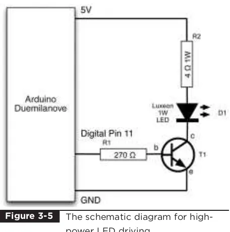
Project 4 High-Brightness Morse Code Translator . . . 35
Summary . . . 40
4 More LED Projects. . . 41
Digital Inputs and Outputs. . . 41
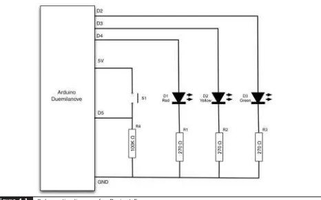
Project 5 Model Traffic Signal . . . 41
Project 6 Strobe Light . . . 44
Project 7 S.A.D. Light . . . 47
Project 8 High-Powered Strobe Light . . . 52
Random Number Generation. . . 55
Project 9 LED Dice . . . 55
Summary . . . 59
5 Sensor Projects . . . 61
Project 10 Keypad Security Code . . . 61
Rotary Encoders. . . 67
Project 11 Model Traffic Signal Using a Rotary Encoder . . . 68
Sensing Light . . . 72
Measuring Temperature . . . 77
Project 13 USB Temperature Logger . . . 77
Summary . . . 83
6 Light Projects. . . 85
Project 14 Multicolor Light Display . . . 85
Seven-Segment LEDs . . . 89
Project 15 Seven-Segment LED Double Dice. . . 91
Project 16 LED Array . . . 95
LCD Displays . . . 101
Project 17 USB Message Board . . . 102
Summary . . . 105
7 Sound Projects. . . 107
Project 18 Oscilloscope . . . 107
Sound Generation . . . 111
Project 19 Tune Player. . . 112
Project 20 Light Harp . . . 117
Project 21 VU Meter . . . 120
Summary . . . 124
8 Power Projects . . . 125
Project 22 LCD Thermostat. . . 125
Project 23 Computer-Controlled Fan. . . 132
H-Bridge Controllers . . . 134
Project 24 Hypnotizer . . . 134
Servo Motors . . . 138
Project 25 Servo-Controlled Laser . . . 138
Summary . . . 142
9 Miscellaneous Projects . . . 145
Project 26 Lie Detector . . . 145
Project 27 Magnetic Door Lock . . . 148
Project 28 Infrared Remote . . . 153
Project 29 Lilypad Clock. . . 159
Project 30 Evil Genius Countdown Timer. . . 163
Summary . . . 168
10 Your Projects . . . 169
Circuits. . . 169
Components . . . 171
Tools. . . 175
Project Ideas. . . 179
Appendix Components and Supplies . . . 181
Suppliers . . . 181
Starter Kit of Components. . . 185
IWOULD LIKEto thank my sons, Stephen and Matthew Monk, for their interest and
encouragement in the writing of this book, their helpful suggestions, and their field testing of projects. Also, I could not have written this book without Linda’s patience and support.
I am grateful to Chris Fitzer for the loan of his oscilloscope, and his good grace after I broke it! I also thank all the “techies” at Momote for taking an interest in the project and humoring me.
Finally, I would like to thank Roger Stewart and Joya Anthony at McGraw-Hill, who have been extremely supportive and enthusiastic, and have been a pleasure to work with.
ARDUINO INTERFACE BOARDSprovide the Evil
Genius with a low-cost, easy-to-use technology to create their evil projects. A whole new breed of projects can now be built that can be controlled from a computer. Before long, the computer-controlled, servo-driven laser will be complete and the world will be at the mercy of the Evil Genius!
This book will show the Evil Genius how to attach an Arduino board to their computer, to program it, and to connect all manner of electronics to it to create projects, including the computer-controlled, servo-driven laser mentioned earlier, a USB-controlled fan, a light harp, a USB temperature logger, a sound oscilloscope, and many more.
Full schematic and construction details are provided for every project, and most can be built without the need for soldering or special tools. However, the more advanced Evil Genius may wish to transfer the projects from a plug-in breadboard to something more permanent, and instructions for this are also provided.
So, What Is Arduino?
Well, Arduino is a small microcontroller board with a USB plug to connect to your computer and a number of connection sockets that can be wired up to external electronics, such as motors, relays, light sensors, laser diodes, loudspeakers,
microphones, etc. They can either be powered through the USB connection from the computer or from a 9V battery. They can be controlled from the computer or programmed by the computer and then disconnected and allowed to work
independently.
At this point, the Evil Genius might be wondering which top secret government organization they need to break into in order to acquire one. Well, disappointingly, no evil deeds at all are required to obtain one of these devices. The Evil Genius needs to go no further than their favorite online auction site or search engine. Since the Arduino is an open-source hardware design, anyone is free to take the designs and create their own clones of the Arduino and sell them, so the market for the boards is competitive. An official Arduino costs about $30, and a clone often less than $20.
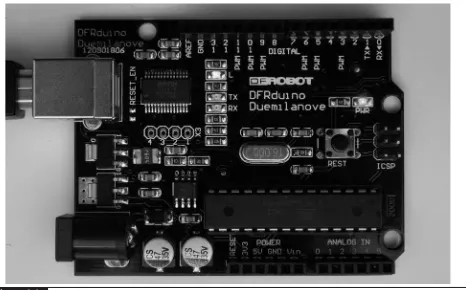
The name “Arduino” is reserved by the original makers. However, clone Arduino designs often have the letters “duino” on the end of their name, for example, Freeduino or DFRduino.
The software for programming your Arduino is easy to use and also freely available for Windows, Mac, and LINUX computers at no cost.
Arduino
Although Arduino is an open-source design for a microcontroller interface board, it is actually rather more than that, as it encompasses the software development tools that you need to program an Arduino board, as well as the board itself. There is a large community of construction, programming, electronics, and even art enthusiasts willing to share their expertise and experience on the Internet.
To begin using Arduino, first go to the Arduino site (www.arduino.cc) and download the software for Mac, PC, or LINUX. You can then either buy an official Arduino by clicking the Buy An
Arduino button or spend some time with your favorite search engine or an online auction site to find lower-cost alternatives. In the next chapter, step-by-step instructions are provided for installing the software on all three platforms.
There are, in fact, several different designs of Arduino board. These are intended for different types of applications. They can all be programmed from the same Arduino development software, and in general, programs that work on one board will work on all.
In this book we mostly use the Arduino Duemilanove, sometimes called Arduino 2009, which is an update of the popular board, the Diecimila. Duemilanove is Italian for 2009, the year of its release. The older Diecimila name means 10,000 in Italian, and was named that after 10,000 boards had been manufactured. Most compatible boards such as the Freeduino are based on the Diecimila and Duemilanove designs.
Most of the projects in this book will work with a Diecimila, Duemilanove, or their clone designs, apart from one project that uses the Arduino Lilypad.
When you are making a project with an
Arduino, you will need to download programs onto the board using a USB lead between your
computer and the Arduino. This is one of the most convenient things about using an Arduino. Many microcontroller boards use separate programming hardware to get programs into the microcontroller. With Arduino, it’s all contained on the board itself. This also has the advantage that you can use the USB connection to pass data back and forth between an Arduino board and your computer. For instance, you could connect a temperature sensor to the Arduino and have it repeatedly tell your computer the temperature.
On the older Diecimila boards, you will find a jumper switch immediately below the USB socket. With the jumper fitted over the top two pins, the board will receive its power from the USB
connection. When over the middle and bottom pins, the board will be powered from an external power supply plugged into the socket below. On the newer Duemilanove boards, there is no such jumper and the supply switches automatically from USB to the 9V socket.
The power supply can be any voltage between 7 and 12 volts. So a small 9V battery will work just fine for portable applications. Typically, while you are making your project, you will probably power it from USB for convenience. When you are ready to cut the umbilical cord (disconnect the USB lead), you will want to power the board independently. This may be with an external power adaptor or simply with a 9V battery connected to a plug to fit the power socket.
There are two rows of connectors on the edges of the board. The row at the top of the diagram is mostly digital (on/off) pins, although any marked with “PWM” can be used as analog outputs. The bottom row of connectors has useful power connections on the left and analog inputs on the right.
These connectors are arranged like this so that so-called “shield” boards can be plugged on to the main board in a piggyback fashion. It is possible to buy ready-made shields for many different
purposes, including:
■ Connection to Ethernet networks ■ LCD displays and touch screens ■ XBee (wireless data communications) ■ Sound
■ Motor control ■ GPS tracking ■ And many more
each other. So a design might have three layers: an Arduino board on the bottom, a GPS shield on it, and then an LCD display shield on top of that.
The Projects
The projects in this book are quite diverse. We begin with some simple examples using standard LEDs and also the ultra high-brightness Luxeon LEDs.
In Chapter 5, we look at various sensor projects for logging temperature and measuring light and pressure. The USB connection to the Arduino makes it possible to take the sensor readings in these projects and pass them back to the computer, where they can be imported into a spreadsheet and charts drawn.
We then look at projects using various types of display technology, including an alphanumeric LCD message board (again using USB to get messages from your computer), as well as seven-segment and multicolor LEDs.
Chapter 7 contains four projects that use sound as well as a simple oscilloscope. We have a simple project to play tunes from a loudspeaker, and build up to a light harp that changes the pitch and volume of the sound by waving your hand over light sensors. This produces an effect rather like the famous Theremin synthesizer. The final project in this chapter uses sound input from a
microphone. It is a VU meter that displays the intensity of the sound on an LED display.
The final chapters contain a mixture of projects. Among others, there is, as we have already
mentioned, an unfathomable binary clock using an Arduino Lilypad board that indicates the time in an obscure binary manner only readable by an Evil Genius, a lie detector, a motor-controlled swirling hypnotizer disk, and, of course, the computer-controlled-servo-guided laser.
Most of the projects in this book can be
constructed without the need for soldering; instead we use a breadboard. A breadboard is a plastic block with holes in it with sprung metal connections behind. Electronic components are pushed through the holes at the front. These are not expensive, and a suitable breadboard is also listed in the appendix. However, if you wish to make your designs more permanent, the book shows you how to do that, too, using the prototyping board.
Sources for all the components are listed in the appendix, along with some useful suppliers. The only things you will need in addition to these components are an Arduino board, a computer, some wire, and a piece of breadboard. The software for all the projects is available for download from www.arduinoevilgenius.com.
Without Further Ado
The Evil Genius is not noted for their patience, so in the next chapter we will show you how to get started with Arduino as quickly as possible. This chapter contains all the instructions for installing the software and programming your Arduino board, including downloading the software for the projects, so you will need to read it before you embark on your projects.
Quickstart
THIS IS A CHAPTERfor the impatient Evil Genius.
Your new Arduino board has arrived and you are eager to have it do something.
So, without further ado...
Powering Up
When you buy an Arduino Diecimila or
Duemilanove board, it is usually preinstalled with a sample Blink program that will make the little built-in LED flash. Figure 1-1 shows an Arduino-compatible board with the LED lit.
The light-emitting diode (LED) marked L is wired up to one of the digital input-output sockets on the board. It is connected to digital pin 13. This really limits pin 13 to being used as an output, but the LED only uses a small amount of current, so you can still connect other things to that connector.
All you need to do to get your Arduino up and running is supply it with some power. The easiest way to do this is to plug in it into the Universal Serial Bus (USB) port on your computer. You will need a type A-to-type B USB lead. This is the same type of lead that is normally used to connect a computer to a printer.
If you are using the older Arduino Diecimila board, make sure that the power jumper is in the USB position (see Figure 1-1). The jumper should connect together the two top pins to allow the board to be powered from the USB. The newer
Arduino Duemilanove boards do not have this jumper and select the power source automatically.
If everything is working okay, the LED should blink once every two seconds. The reason that new Arduino boards have this Blink sketch already installed is to verify that the board works. If your board does not start to blink when connected, check the position of the power jumper (if it has one) and try a different USB socket, possibly on a different computer, as some USB sockets are capable of supplying more power than others. Also, clicking the Reset button should cause the LED to flicker momentarily. If this is the case, but the LED does not flash, then it may just be that the board has not been programmed with the Flash sketch; but do not despair, as once everything is installed, we are going to modify and install that script anyway as our first project.
Installing the Software
Now we have our Arduino working, let’s get the software installed so that we can alter the Blink program and send it down to the board. The exact procedure depends on what operating system you use on your computer. But the basic principle is the same for all.
Install the USB driver that allows the computer to talk to the Arduino’s USB port. It uses this for programming and sending messages.
Install the Arduino development environment, which is the program that you run on your computer that enables you to write sketches and download them to the Arduino board.
The Arduino website (www.arduino.cc) contains the latest version of the software.
Installation on Windows
Follow the download link on the Arduino home page (www.arduino.cc) and select the download for Windows. This will start the download of the Zip archive containing the Arduino software, as shown in Figure 1-2. You may well be
downloading a more recent version of the software than the version 17 shown. This should not matter, but if you experience any problems, refer back to the instructions on the Arduino home page.
The Arduino software does not distinguish between different versions of Windows. The download should work for all versions, from Windows XP onwards. The following instructions are for Windows XP.
Select the Save option from the dialog, and save the Zip file onto your desktop. The folder
contained in the Zip file will become your main Arduino directory, so now unzip it into C:\Program Files\Arduino.
You can do this in Windows XP by right-clicking the Zip file to show the menu in Figure 1-3 and selecting the Extract All option. This will open the Extraction Wizard, shown in Figure 1-4.
A powered-up Arduino board with LED lit.
Figure 1-1
Downloading the Arduino software for Windows.
Click Next and then modify the folder to extract files to C:\Program Files\Arduino as shown in Figure 1-5. Then click Next again.
This will create a new directory for this version of Arduino (in this case, 17) in the folder
C:\Program Files\Arduino. This allows you to have multiple versions of Arduino installed at the same time, each in its own folder. Updates of Arduino are fairly infrequent and historically have always kept compatibility with earlier versions of the software. So unless there is a new feature of the software that you want to use, or you have been having problems, it is by no means essential to keep up with the latest version.
Now that we have got the Arduino folder in the right place, we need to install the USB drivers. We let Windows do this for us by plugging in the Arduino board to trigger the Windows Found New Hardware Wizard shown in Figure 1-6.
Select the option No, Not This Time, and then click Next.
On the next screen (Figure 1-7), click the option to install from a specified location, enter or browse to the location C:\Program Files\Arduino\arduino-0017\drivers\FTDI USB Drivers, and then click Next. Note that you will have to change 0017 in the path noted if you download a different version.
The installation will then complete and you are ready to start up the Arduino software itself. To do this, go to My Computer, navigate to C:\Program
The Extract All menu option in Windows.
Figure 1-3
Extracting the Arduino file in Windows.
Figure 1-4
Setting the directory for extraction.
Files\Arduino\arduino-0017, and click the Arduino icon, as shown in Figure 1-8. The Arduino
software will now start.
Note that there is no shortcut created for the Arduino program, so you may wish to select the Arduino program icon, right-click, and create a shortcut that you can then drag to your desktop.
The next two sections describe this same procedure for installing on Mac and LINUX computers, so if you are a Windows user, you can skip these sections.
Installation on Mac OS X
The process for installing the Arduino software on the Mac is a lot easier than on the PC.
Windows Found New Hardware Wizard.
Figure 1-6 Setting the location of the USB
drivers.
Figure 1-7
Starting the Arduino software from Windows.
As before, the first step is to download the file. In the case of the Mac, it is a disk image file. Once downloaded, it will mount the disk image and open a Finder window, as shown in Figure 1-9. The Arduino application itself is installed in the usual Mac way by dragging it from the disk image to your Applications folder.
The disk image also contains two installer packages for the USB drivers (see Figure 1-10). Be sure to choose the package for your system
architecture. Unless you are using a Mac built before March 2006, you will need to use the Intel version rather than the PPC version.
When you run the installer, you can simply click Continue until you come to the Select Disk screen, where you must select the hard disk before
clicking Continue. As this software installs a kernel extension, it will prompt you to enter your password before completing the installation.
You can now find and launch the Arduino software in your Applications folder. As you are going to use it frequently, you may wish to right-click its icon in the dock and set it to Keep In Dock.
You can now skip the next subsection, which is for installation on LINUX.
Installation on LINUX
There are many different LINUX distributions, and for the latest information, refer to the Arduino home page. However, for most versions of LINUX, installation is straightforward. Your LINUX will
Installing the Arduino software on Mac OS X.
Figure 1-9
Installing the USB drivers on Mac OS X.
probably already have the USB drivers installed, the AVR-GCC libraries, and the Java environment that the Arduino software needs.
So, if you are lucky, all you will need to do is download the TGZ file for the Arduino software from the Arduino home page (www.arduino.cc), extract it, and that is your working Arduino directory.
If, on the other hand, you are unlucky, then as a LINUX user, you are probably already adept at finding support from the LINUX community for setting up your system. The pre-requisites that you will need to install are Java runtime 5 or later and the latest AVR-GCC libraries.
Entering into Google the phrase “Installing Arduino on SUSE LINUX,” or whatever your distribution of LINUX is, will, no doubt, find you lots of helpful material.
Configuring Your Arduino
Environment
Whatever type of computer you use, you should now have the Arduino software installed on it. We now need to make a few settings. We need to specify the operating system name for the port that is connected to the USB port for communicating with the Arduino board, and we need to specify the type of Arduino board that we are using. But first, you need to connect your Arduino to your
computer using the USB port or you will not be able to select the serial port.
The serial port is set from the Tools menu, as shown in Figure 1-11 for the Mac and in Figure 1-12 for Windows—the list of ports for LINUX is similar to the Mac.
If you use many USB or Bluetooth devices with your Mac, you are likely to have quite a few options in this list. Select the item in the list that begins with “dev/tty.usbserial.”
On Windows, the serial port can just be set to COM3.
From the Tools menu, we can now select the board that we are going to use, as shown in Figure 1-13. If you are using the newer Duemilanove, choose the first option. However, if you are using the older Diecimila board, select the second option.
Downloading the
Project Software
The software for all of these sketches is available for download. The whole download is less than a megabyte, so it makes sense to download the software for all of the projects, even if you only intend to use a few. To download them, browse to www.arduinoevilgenius.com and click Downloads at the top of the screen.
Setting the serial port on the Mac.
Setting the board.
Figure 1-13
Click the evil_genius.zip link to download a Zip file of all the projects. If you are using Windows, unzip the file to My Documents\Arduino. On a Mac and LINUX, you should unzip it to Documents/Arduino in your home directory.
Once the files are installed, you will be able to access them from the File | Sketchbook menu on the Arduino software.
Project 1
Flashing LED
Having assumed that we have successfully
installed the software, we can now start on our first exciting project. Actually, it’s not that exciting, but we need to start somewhere, and this will ensure that we have everything set up correctly to use our Arduino board.
We are going to modify the example Blink sketch that comes with Arduino. We will increase the frequency of the blinking and then install the modified sketch on our Arduino board. Rather than blink slowly, our board will flash its LED quickly. We will then take the project a stage further by
using a bigger external LED and resistor rather than the tiny built-in LED.
Software
First, we need to load the Blink sketch into the Arduino software. The Blink sketch is included as an example when you install the Arduino
environment. So we can load it using the File menu, as shown in Figure 1-14.
The majority of the text in this sketch is in the form of comments. Comments are not actually part of the program but explain what is going on in the program to anyone reading the sketch.
Comments can be single-line comments that start after a // and continue to the end of the line, or they can be multiline comments that start with a /* and end some lines later with a */.
If all the comments in a sketch were to be removed, it would still work in exactly the same way, but we use comments because they are useful to anyone reading the sketch trying to work out what it does.
Before we start, a little word about vocabulary is required. The Arduino community uses the word “sketch” in place of “program,” so from now on, I will refer to our Arduino programs as sketches. Occasionally I may refer to “code.” Code is programmer speak for a section of a program or even as a generic term for what is written when creating a program. So, someone might say, “I wrote a program to do that,” or they could say, “I wrote some code to do that.”
To modify the rate at which the LED will blink, we need to change the value of the delay so that in the two places in the sketch where we have:
delay(1000);
Description Appendix
Arduino Diecimila or
Duemilanove board or clone 1
D1 5-mm red LED 23
R1 270 ⍀0.5W metal film resistor 6
■ In actual fact, almost any commonly available LED and 270 ⍀resistor will be fine.
■ No tools other than a pair of pliers or wire cutters are required.
■ The number in the Appendix column refers to the component listing in the appendix, which lists part numbers for various suppliers.
change the value in the parentheses to 200 so that it appears as:
delay(200);
This is changing the delay between turning the LED on and off from 1000 milliseconds (1 second) to 200 milliseconds (1/5th of a second). In Chapter 3 we will explore this sketch further, but for now, we will just change the delay and download the sketch to the Arduino board.
With the board connected to your computer, click the Upload button on the Arduino. This is shown in Figure 1-15. If everything is okay, there
will be a short pause and then the two red LEDs on the board will start flashing away furiously as the sketch is uploaded onto the board. This should take around 5 to 10 seconds.
If this does not happen, check the serial port and board type settings as described in the previous sections.
When the completed sketch has been installed, the board will automatically reset, and if
everything has worked, you will see the LED for digital port 13 start to flash much more quickly than before.
Loading the example Blink sketch.
Figure 1-14
Uploading the sketch to the Arduino board.
Hardware
At the moment, this doesn’t really seem like real electronics because the hardware is all
contained on the Arduino board. In this section, we will add an external LED to the board.
LEDs cannot simply have voltage applied to them; they must have a current-limiting resistor attached. Both parts are readily available from any electronics suppliers. The component order codes for a number of suppliers are detailed in the appendix.
The Arduino board connectors are designed to attach “shield” plug-in boards. However, for experimentation purposes, they also allow wires or component leads to be inserted directly into the sockets.
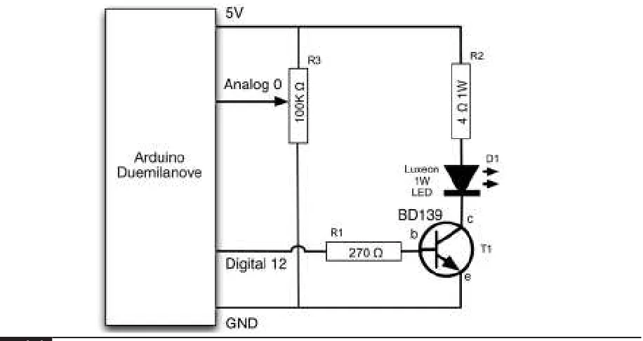
Figure 1-16 shows the schematic diagram for attaching the external LED.
This kind of schematic diagram uses special symbols to represent the electronic components. The LED appears rather like an arrow, which indicates that light-emitting diodes, in common with all diodes, only allow the current to flow in
one direction. The little arrows next to the LED symbol indicate that it emits light.
The resistor is just depicted as a rectangle. Resistors are also often shown as a zigzag line. The rest of the lines on the diagram represent electrical connections between the components. These connections may be lengths of wire or tracks on a circuit board. In this case, they will just be the wires of the components.
We can connect the components directly to the Arduino sockets between the digital pin 12 and the GND pin, but first we need to connect one lead of the LED to one lead of the resistor.
It does not matter which lead of the resistor is connected to the LED; however, the LED must be connected the correct way. The LED will have one lead slightly longer than the other, and it is the longer lead that must be connected to digital pin 12 and the shorter lead that should be connected to the resistor. LEDs and some other components have the convention of making the positive lead longer than the negative one.
To connect the resistor to the short lead of the LED, gently spread the leads apart and twist the short lead around one of the resistor leads, as shown in Figure 1-17.
Then push the LED’s long lead into the digital pin 12 and the free lead of the resistor into one of
Schematic diagram for an LED connected to the Arduino board.
Figure 1-16 An LED connected to a serial
resistor.
the two GND sockets. This is shown in Figure 1-18. Sometimes, it helps to bend a slight kink into the end of the lead so that it fits more tightly into the sockets.
We can now modify our sketch to use the external LED that we have just connected. All we need to do is change the sketch so that it uses digital pin 12 instead of 13 for the LED. To do this, we change the line:
int ledPin = 13;
// LED connected to digital pin 13
to read:
int ledPin = 12;
// LED connected to digital pin 12
Now upload the sketch by clicking the Upload To IO Board button in the same way as you did when modifying the flash rate.
Breadboard
Twisting together a few wires is not practical for anything much more than a single LED. A
breadboard allows us to build complicated circuits without the need for soldering. In fact, it is a good idea to build all circuits on a breadboard first to get the design right and then commit the design to solder once everything is working.
A breadboard comprises a plastic block with holes in it, with sprung metal connections behind. Electronic components are pushed through the holes at the front.
Underneath the breadboard holes, there are strips of connectors, so each of the holes in a strip are connected together. The strips have a gap between them so that integrated circuits in dual-in-line packaging can be inserted without leads on the same row being shorted together.
An LED connected to the Arduino board.
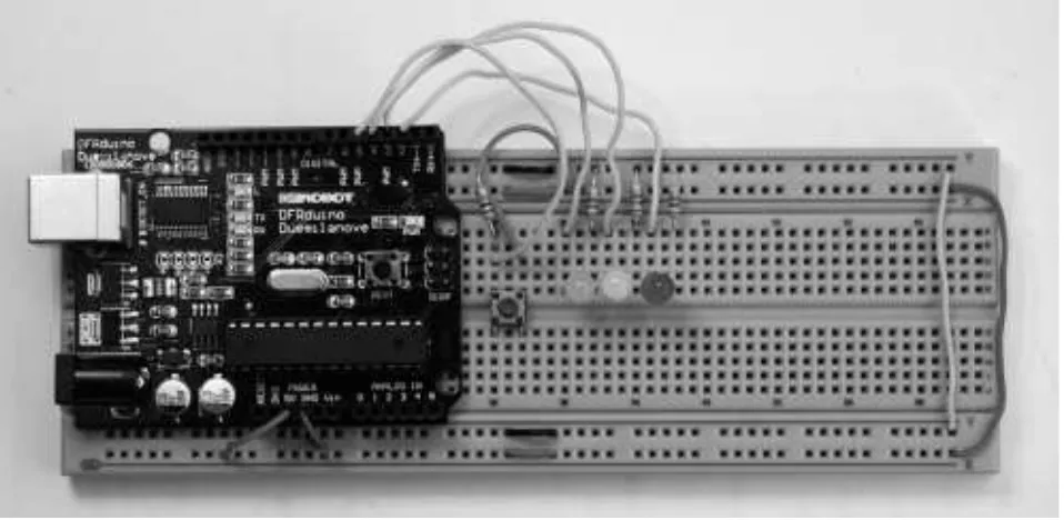
We can build this project on a breadboard rather than with twisted wires. Figure 1-19 shows a photograph of this. Figure 1-20 makes it a little easier to see how the components are positioned and connected together.
You will notice that at the edges of the breadboard (top and bottom), there are two long horizontal strips. The connections on the back of these long strips run at right angles to the normal strips of connections and are used to provide power to the components on the breadboard. Normally, there is one for ground (0V or GND) and one for the positive supply voltage (usually 5V). There are little linking wires between the left and right halves of the GND strip, as on this
breadboard, as it does not go the whole width of the board.
In addition to a breadboard, you will need some solid-core wire and some wire strippers or pliers to cut and remove the insulation from the ends of the wire. It is a good idea to have at least three different colors: red for all wires connected to the positive side of the supply, black for negative, and some other color (orange or yellow) for other connections. This makes it much easier to understand the layout of the circuit. You can also buy prepared short lengths of solid-core wire in a variety of colors. Note that it is not advisable to use multicore wire, as it will tend to bunch up when you try to push it into the breadboard holes.
Project 1 on breadboard.
Figure 1-19
Project 1 breadboard layout.
Possible sources of these materials are included in the appendix.
We can straighten out the wires of our LED and resistor and plug them into a breadboard. It is best to use a reasonable-sized breadboard and attach the Arduino board to it. You probably do not want to attach the board permanently, so I use a small lump of adhesive putty. However, you may find it easier to dedicate one Arduino board to be your
design board and leave it permanently attached to the breadboard.
Summary
A Tour of Arduino
15 IN THIS CHAPTER, we look at the hardware of the
Arduino board and also of the microcontroller at its heart. In fact, the board basically just provides support to the microcontroller, extending its pins to the connectors so that you can connect hardware to them and providing a USB link for downloading sketches, etc.
We also learn a few things about the C language used to program the Arduino, something we will build on in later chapters as we start on some practical project work.
Although this chapter gets quite theoretical at times, it will help you understand how your
projects work. However, if you would prefer just to get on with your projects, you may wish to skim this chapter.
Microcontrollers
The heart of our Arduino is a microcontroller. Practically everything else on the board is concerned with providing the board with power and allowing it to communicate with your desktop computer.
So what exactly do we get when we buy one of these little computers to use in our projects?
The answer is that we really do get a little computer on a chip. It has everything and more than the first home computers had. It has a
processor, a kilobyte of random access memory (RAM) for holding data, a few kilobytes of erasable programmable read-only memory (EPROM) or Flash memory for holding our programs, and it has input and output pins. These input/output pins are what link the microcontroller to the rest of our electronics.
Inputs can read both digital (is the switch on or off?) and analog (what is the voltage at a pin?). This enables us to connect many different types of sensors for light, temperature, sound, etc.
Outputs can also be analog or digital. So, you can set a pin to be on or off (0V or 5V) and this can turn LEDs on and off directly, or you can use the output to control higher-power devices such as motors. They can also provide an analog output voltage. That is, you can set the output of a pin to some particular voltage, allowing you to control the speed of a motor or the brightness of a light, for example, rather than simply turning it on or off.
What’s on an Arduino Board?
Power Supply
Directly below the USB connector is the 5V voltage regulator. This regulates whatever voltage (between 7 and 12 volts) is supplied from the power socket into a constant 5V.
5V (along with 3V, 6V, 9V, and 12V) is a bit of a standard voltage in electronics. 3, 6, and 9V are standard because the voltage that you get from a single alkaline cell is 1.5V, and these are all convenient multiples of 1.5V, which is what you get when you make a “battery” of two, three, six, or eight cells.
So if that is the case, you might be wondering why 5V? You cannot make that using 1.5V cells. Well, the answer lies in the fact that in the early days of computing, a range of chips became available, each of which contained logic gates. These chips used something called TTL (Transistor-Transistor Logic), which was a bit fussy about its voltage requirements and required
something between 4.5V and 5.5V. So 5V became the standard voltage for all digital electronics.
These days, the type of logic gates used in chips has changed and they are far more tolerant of different voltages.
The 5V voltage regulator chip is actually quite big for a surface-mount component. This is so that it can dissipate the heat required to regulate the voltage at a reasonably high current, which is useful when driving our external electronics.
Power Connections
Next, let us look at the connectors at the bottom of Figure 2-1. You can read the connection names next to the connectors.
The first is Reset. This does the same thing as pressing the Reset button on the Arduino. Rather like rebooting a PC, it resets the microcontroller, beginning its program from the start. The Reset connector allows you to reset the microcontroller
The components of an Arduino board.
by momentarily setting this pin high (connecting it to +5V).
The rest of the pins in this section provide different voltages (3.3, 5, GND, and 9), as labeled. GND, or ground, just means zero volts. It is the reference voltage to which all other voltages on the board are relative.
At this point, it would be useful to remind the reader about the difference between voltage and current. There is no perfect analogy for the
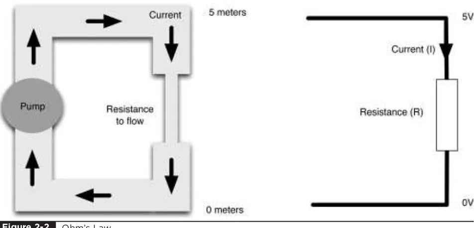
behavior of electrons in a wire, but the author finds an analogy with water in pipes to be helpful, particularly in dealing with voltage, current, and resistance. The relationship between these three things is called Ohm’s Law.
Figure 2-2 summarizes the relationship between voltage, current, and resistance. The left side of the diagram shows a circuit of pipes, where the top of the diagram is higher up (in elevation) than the bottom of the diagram. So water will naturally flow from the top of the diagram to the bottom. Two factors determine how much water passes any point in the circuit in a given time (the current):
■ The height of the water (or if you prefer, the
pressure generated by the pump). This is like voltage in electronics.
■ The resistance to flow offered by the
constriction in the pipework
The more powerful the pump, the higher the water can be pumped and the greater the current that will flow through the system. On the other hand, the greater the resistance offered by the pipework, the lower the current.
In the right half of Figure 2-2, we can see the electronic equivalent of our pipework. In this case, current is actually a measure of how many
electrons flow past a point per second. And yes, resistance is the resistance to the flow of electrons.
Instead of height or pressure, we have a concept of voltage. The bottom of the diagram is at 0V, or ground, and we have shown the top of the diagram as being at 5V. So the current that flows (I) will be the voltage difference (5) divided by the resistance R.
Ohm’s Law is usually written as V ⫽IR. Normally, we know what V is and are trying to
Ohm’s Law.
calculate R or I, so we can do a bit of rearranging to have the more convenient I ⫽V/R and R ⫽V/I.
It is very important to do a few calculations using Ohm’s Law when connecting things to your Arduino, or you may damage it if you ask it to supply too much current. Generally, though, the Arduino boards are remarkably tolerant of accidental abuse.
So, going back to our Arduino power pins, we can see that the Arduino board will supply us with useful voltages of 3.3V, 5V, and 9V. We can use any of those supplies to cause a current to flow, as long as we are careful not to make it a short circuit (no resistance to flow), which would cause a potentially large current to flow that could cause damage. In other words, we have to make sure that anything we connect to the supply has enough resistance to prevent too much current from flowing. As well as supplying a particular voltage, each of those supply connections will have a maximum current that can be allowed to flow. Those currents are 50 mA (thousandths of an amp) for the 3.3V supply, and although it is not stated in the Arduino specification, probably around 300 mA for the 5V.
Analog Inputs
The next section of connections is labeled Analog In 0 to 5. These six pins can be used to measure the voltage connected to them so that the value can be used in a sketch. Note that they measure a voltage and not a current. Only a tiny current will ever flow into them and down to ground because they have a very large internal resistance.
Although labeled as analog inputs, these connections can also be used as digital inputs or outputs, but by default, they are analog inputs.
Digital Connections
We now switch to the top connector and start on the right side (Figure 2-1). We have pins labeled
Digital 0 to 13. These can be used as either inputs or outputs. When using them as outputs, they behave rather like the supply voltages we talked about earlier, except that these are all 5V and can be turned on or off from our sketch. So, if we turn them on from our sketch, they will be at 5V and if we turn them off, they will be at 0V. As with the supply connectors, we have to be careful not to exceed their maximum current capabilities.
These connections can supply 40 mA at 5V. That is more than enough to light a standard LED, but not enough to drive an electric motor directly.
As an example, let us look at how we would connect an LED to one of these digital
connections. In fact, let’s go back to Project 1 in Chapter 1.
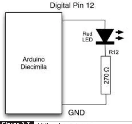
As a reminder, Figure 2-3 shows the schematic diagram for driving the LED that we first used in the previous chapter. If we were to not use a resistor with our LED but simply connect the LED between pin 12 and GND, then when we turned digital output 12 on (5V), we might burn out the LED, destroying it.
This is because LEDs have a very low resistance and will cause a very high current to flow unless they are protected from themselves by using a resistor to limit the flow of current.
LED and series resistor.
An LED needs about 10 mA to shine reasonably brightly. The Arduino can supply 50 mA, so there is no problem there; we just need to choose a sensible value of resistor.
LEDs have the interesting property that no matter how much current flows through them, there will always be about 2V between their pins. We can use this fact and Ohm’s Law to work out the right value of resistor to use.
We know that (at least when it’s on) the output pin will be supplying 5V. Now, we have just said that 2V will be “dropped” by our LED, leaving 3V (5 – 2) across our current-limiting resistor. We want the current flowing around the circuit to be 10 mA, so we can see that the value for the
Resistors come in standard values, and the closest value to 300 ⍀is 270 ⍀. This means that instead of 10 mA, the current will actually be
I⫽V/R
I⫽3/270
I⫽11.111 mA
These things are not critical, and the LED would probably be equally happy with anything between 5 and 30 mA, so 270 ⍀will work just fine.
We can also set one of these digital connections to be an input, in which case, it works rather like an analog input, except that it will just tell us if the voltage at a pin is above a certain threshold
(roughly 2.5V) or not.
Some of the digital connections (3, 5, 6, 9, 10, and 11) have the letters PWM next to them. These can be used to provide a variable output voltage rather than a simple 5V or nothing.
On the left side of the top connector in Figure 2-1, there is another GND connection and a connection called AREF. AREF can be used to scale the readings for analog inputs. This is rarely used and can safely be ignored.
Microcontroller
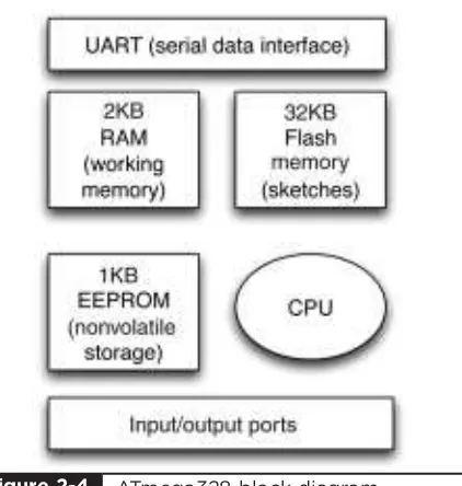
Getting back to our tour of the Arduino board, the microcontroller chip itself is the black rectangular device with 28 pins. This is fitted into a DIL (dual in-line) socket so that it can be easily replaced. The 28-pin microcontroller chip used on Arduino Duemilanove is the ATmega328. Figure 2-4 is a block diagram showing the main features of this device.
The heart, or perhaps more appropriately the brain, of the device is the CPU (central processing unit). It controls everything that goes on within the device. It fetches program instructions stored in the Flash memory and executes them. This might involve fetching data from working memory (RAM), changing it, and then putting it back. Or, it may mean changing one of the digital outputs from 0 to 5 volts.
ATmega328 block diagram.
The electrically erasable programmable read-only memory (EEPROM) memory is a little like the Flash memory in that it is nonvolatile. That is, you can turn the device off and on and it will not have forgotten what is in the EEPROM. Whereas the Flash memory is intended for storing program instructions (from sketches), the EEPROM is used to store data that you do not want to lose in the event of a reset or power failure.
The older Diecimila uses the ATmega168, which functions in an identical way to the ATmega328 except that it has half the amount of every sort of memory. It has 16KB of Flash memory, 1KB of RAM, and 512 bytes of EEPROM.
Other Components
Above the microcontroller there is a small, silver, rectangular component. This is a quartz crystal oscillator. It “ticks” 16 million times a second, and on each of those ticks, the microcontroller can perform one operation—an addition, subtraction, etc.
To the right of the crystal, is the Reset switch. Clicking this sends a logic pulse to the Reset pin of the microcontroller, causing the microcontroller to start its program afresh and clear its memory. Note that any program stored on the device will be retained because this is kept in nonvolatile Flash memory—that is, memory that remembers even when the device is not powered.
To the right of the Reset button is the serial programming connector. It offers another means of programming the Arduino without using the USB port. Since we do have a USB connection and software that makes it convenient to use, we will not avail ourselves of this feature.
In the top left of the board next to the USB socket is the USB interface chip. This converts the signal levels used by the USB standard to levels that can be used directly by the Arduino board.
The Arduino Family
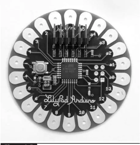
It’s useful to have a little background on the Arduino boards. We will be using the Duemilanove for most of our projects; however, we will also dabble with the interesting Lilypad Arduino.
The Lilypad (Figure 2-5), is a tiny, thin Arduino board that can be stitched into clothing for
applications that have become known as wearable computing. It does not have a USB connection, and you must use a separate adaptor to program it. This is an exceptionally beautiful design. Inspired by its clocklike appearance, we will use this in Project 29 (Unfathomable Binary Clock).
At the other end of the spectrum is the Arduino Mega. This board has a faster processor with more memory and a greater number of input/output pins.
Cleverly, the Arduino Mega can still use shields built for the smaller Arduino Diecimila and Duemilanove boards, which sit at the front of the board, allowing access to the double row of connectors for the Mega’s additional connections at the rear. Only the most demanding of projects really need an Arduino Mega.
Arduino Lilypad.
The C Language
Many languages are used to program microcontrollers, from hard-core Assembly language to graphical programming languages like Flowcode. Arduino sits somewhere in between these two extremes and uses the C programming language. It does, however, wrap up the C language, hiding away some of the complexity. This makes it easy to get started.
The C language is, in computing terms, an old and venerable language. It is well suited to programming the microcontroller because it was invented at a time when compared to today’s monsters, the typical computer was quite poorly endowed.
C is an easy language to learn, yet compiles into efficient machine code that only takes a small amount of room in our limited Arduino memory.
An Example
We are now going to examine the sketch for Project 1 in a bit more detail. The listing for this sketch to flash an LED on and off is shown here. We have ignored all the lines that begin with // or blocks of lines that start with /* and end with */ because these are comment lines that have no effect on the program and are just there for information.
int ledPin = 13;
// LED connected to digital pin 13 void setup()
digitalWrite(ledPin, HIGH); // set the LED on
delay(1000); // wait for a second
digitalWrite(ledPin, LOW); // set the LED off
delay(1000); // wait for a second
}
It is standard practice to include such text at the top of any program file. You can also include comments that describe a tricky bit of code, or anything that requires some explanation.
The Arduino development environment uses something called a compiler that converts the script into the machine code that will run on the microcontroller.
So, moving onto the first real line of code, we have:
int ledPin = 13;
This line of code gives a name to the digital output pin that we are going to connect to the LED. If you look carefully at your Arduino board, you will see the connector for pin 13 between GND and pin 12 on the Arduino’s top connector. The Arduino board has a small green LED already soldered onto the board and connected to pin 13. We are going to change the voltage of this pin to between 0V and 5V to make the LED flash.
We are going to use a name for the pin so that it’s easy to change it and use a different one. You can see that we refer to “ledPin” later in the sketch. You may prefer to use pin 12 and the external LED that you used with your breadboard in Chapter 1. But for now, we will assume that you are using the built-in LED attached to pin 13.
You will notice that we did not just write:
led pin = 13
So, we start each word (apart from the first) with an uppercase letter and remove the space; that gives us:
ledPin = 13
The word ledPin is what is termed a variable. When you want to use a variable for the first time in a sketch, you have to tell the compiler what type of variable it is. It may be an int, as is the case here, or a float, or a number of other types that we will describe later in this chapter.
An int is an integer—that is, a whole number— which is just what we need when referring to a particular pin on the Arduino. There is, after all, no pin 12.5, so it would not be appropriate to use a floating point number (float).
The syntax for a variable declaration is
type variableName = value;
So first we have the type (int), then a space, then a variable name in bumpy case (ledPin), then an equal sign, then a value, and finally a semicolon to indicate the end of the line:
int ledPin = 13;
As I mentioned, the compiler is fussy, so if you forget the semicolon, you will receive an error message when you compile the sketch. Try removing the semicolon and clicking the Play button. You should see a message like this:
error: expected unqualified-id before numeric constant
It’s not exactly “you forgot a semicolon,” and it is not uncommon for error messages to be
similarly misleading.
The next lines of the sketch are
void setup() // run once, when the sketch starts {
pinMode(ledPin, OUTPUT); // sets the digital pin as output }
This is what is called a function, and in this case, the function is called setup. Every sketch must contain a setup function, and the lines of code inside the function surrounded by curly brackets will be carried out in the order that they are written. In this case, that is just the line starting with pinMode.
A good starting point for any new project is to copy this example project and then alter it to your needs.
We will not worry too much about functions at this stage, other than to say that the setup function will be run every time the Arduino is reset, including when the power is first turned on. It will also be run every time a new sketch is
downloaded.
In this case, the only line of code in setup is
pinMode(ledPin, OUTPUT);
// sets the digital pin as output
The first thing to mention is that we have a different type of comment on the end of this line. That is, the single-line comment. This begins with a // and ends at the end of the line.
The line can be thought of as a command to the Arduino to use the ledPin as a digital output. If we had a switch connected to ledPin, we could set it as an input using:
pinMode(ledPin, INPUT);
The words INPUT and OUTPUT are what are called constants. They will actually be defined within C to be a number. INPUT may be defined as 0 and OUPUT as 1, but you never need to actually see what number is used, as you always refer to them as INPUT or OUTPUT. Later in this chapter, we will see two more constants, HIGH and LOW, that are used when setting the output of a digital pin to +5V or 0V, respectively.
The next section of code is another function that every Arduino sketch must have; it is called loop:
void loop() {
digitalWrite(ledPin, HIGH); // sets the LED on
delay(1000); // waits for a second
digitalWrite(ledPin, LOW); // sets the LED off
delay(1000); // waits for a second
}
The function loop will be run continuously until the Arduino is powered down. That is, as soon as it finishes executing the commands it contains, it will begin again. Remember that an Arduino board is capable of running 16 million commands per second, so things inside the loop will happen frequently if you let them.
In this case, what we want the Arduino to keep doing continuously is to turn the LED on, wait a second, turn the LED off, and then wait another second. When it has finished doing this, it will begin again, turning the LED on. In this way it will go round the loop forever.
By now, the command syntax for digitalWrite and delay will be becoming more familiar. Although we can think of them as commands that are sent to the Arduino board, they are actually functions just like setup and loop, but in this case they have what are called parameters. In the case
of digitalWrite, it is said to take two parameters: the Arduino pin to write to and the value to write.
In our example, we pass the parameters of ledPin and HIGH to turn the LED on and then ledPin and LOW to turn it off again.
Variables and Data Types
We have already met the variable ledPin and declared it to be of type int. Most of the variables that you use in your sketches are also likely to be ints. An int holds an integer number between –32,768 and +32,767. This uses just two bytes of data for each number stored from the 1024 available bytes of storage on an Arduino. If that range is not enough, you can use a long, which uses four bytes for each number and will give you a range of numbers from –2,147,483,648 to +2,147,483,647.
Most of the time, an int represents a good compromise between precision and use of memory.
If you are new to programming, I would use ints for almost everything and gradually expand your repertoire of data types as your experience grows.
Other data types available to you are summarized in Table 2-1.
One thing to consider is that if data types exceed their range, strange things happen. So if you have a byte variable with 255 in it and you add 1 to it, you get 0. More alarmingly, if you have an int variable with 32,767 and you add 1 to it, you will end up with –32,768.
Until you are completely happy with these different data types, I would recommend sticking to int, as it works for practically everything.
Arithmetic
input to turn it into a temperature, or more typically, add 1 to a counter variable.
When you are performing some calculation, you need to be able to assign the result of the
calculation to a variable.
The following lines of code contain two assignments. The first gives the variable y the value 50 and the second gives the variable x the value of y + 100.
y = 50; x = y + 100;
Strings
When programmers talk of Strings, they are referring to a string of characters such as the much-used message “Hello World.” In the world of Arduino, there are a couple of situations where you
might want to use Strings: when writing messages to an LCD display or sending back serial text data over the USB connection.
Strings are created using the following syntax:
char* message = "Hello World";
The char* word indicates that the variable message is a pointer to a character. For now, we do not need to worry too much about how this works. We will meet this later in the book when we look at interfacing with textual LCD displays.
Conditional Statements
Conditional statements are a means of making decisions in a sketch. For instance, your sketch may turn the LED on if the value of a temperature variable falls below a certain threshold.
Type Memory (bytes) Range Notes
boolean 1 true or false (0 or 1)
char 1 –128 to +128 Used to represent an ASCII character code (e.g., A is represented as 65). Its negative numbers are not normally used.
byte 1 0 to 255
int 2 –32,768 to +32,767
unsigned int 2 0 to 65,536 Can be used for extra precision where negative numbers are not needed. Use with caution, as arithmetic with ints may cause unexpected results.
long 4 –2,147,483,648 to Needed only for representing very 2,147,483,647 large numbers.
unsigned long 4 0 to 4,294,967,295 See unsigned int.
float 4 –3.4028235E+38 to + 3.4028235E+38
The code for this is shown here:
if (temperature < 15) {
digitalWrite(ledPort, HIGH); }
The line or lines of code inside the curly braces will only be executed if the condition after the if keyword is true.
The condition has to be contained in parentheses, and is what programmers call a logical expression. A logical expression is like a mathematical sentence that must always return one of two possible values: true or false.
The following expression will return true if the value in the temperature variable is less than 15:
(temperature < 15)
As well as <, you have: >, <=, and >=.
To see if two numbers are equal, you can use == and to test if they are not equal, you can use !=.
So the following expression would return true if the temperature variable had a value that was anything except 15:
(temperature != 15)
You can also make complex conditions using what are called logical operators. The principal operators being && (and) and || (or).
So an example that turned the LED on if the temperature was less than 15 or greater than 20 might look like this:
if ((temperature < 15) || (temperature > 20))
{
digitalWrite(ledPort, HIGH); }
Often, when using an if statement, you want to do one thing if the condition is true and a different thing if it is false. You can do this by using the else keyword, as shown in the following example. Note the use of nested parentheses to make it clear what is being or’d with what.
if ((temperature < 15) || (temperature > 20))
In this chapter, we have explored the hardware provided by the Arduino and refreshed our knowledge of a little elementary electronics.
We have also started our exploration of the C programming language. Don’t worry if you found some of this hard to follow. There is a lot to take in if you are not familiar with electronics, and while the author’s goal is to explain how everything works, you are completely at liberty to simply start on the projects first and come back to the theory when you are ready.
LED Projects
27 IN THIS CHAPTER,we are going to start building
some LED-based projects. We will keep the hardware fairly simple so that we can concentrate on the programming of the Arduino.
Programming microcontrollers can be a tricky business requiring an intimate knowledge of the inner workings of the device: fuses, registers, etc. This is, in part, because modern microcontrollers are almost infinitely configurable. Arduino standardizes its hardware configuration, which, in return for a small loss of flexibility, makes the devices a great deal easier to program.
Project 2
Morse Code S.O.S. Flasher
Morse code used to be a vital method of
communication in the 19th and 20th centuries. Its coding of letters as a series of long and short dots meant that it could be sent over telegraph wires, over a radio link, and using signaling lights. The letters S.O.S. (Save Our Souls) is still recognized as an international signal of distress.
In this project, we will make our LED flash the sequence S.O.S. over and over again.
For this project, you will need just the same components as for Project 1.
Hardware
The hardware is exactly the same as Project 1. So, you can either just plug the resistor and LED directly into the Arduino connectors or use a breadboard (see Chapter 1).
Software
Rather than start typing this project in from scratch, we will use Project 1 as a starting point. So if you have not already done so, please complete Project 1.
If you have not already done so, download the project code from www.arduinoevilgenius.com; then you can also just load the completed sketch for Project 1 from your Arduino Sketchbook and download it to the board (see Chapter 1). However,
Description Appendix
Arduino Diecimila or
Duemilanove board or clone 1
D1 5-mm red LED 23
R1 270 ⍀0.5W metal film resistor 6
■ Almost any commonly available LED and 270
⍀resistor will be fine.
■ No tools other than a pair of pliers or wire cutters are required.
it will help you understand Arduino better if you modify the sketch from Project 1 as suggested next.
Modify the loop function of Project 1 so that it now appears as shown here. Note that copy and paste is highly recommended in this kind of situation:
void loop() {
digitalWrite(ledPin, HIGH); // S (...) first dot
delay(200);
digitalWrite(ledPin, LOW); delay(200);
digitalWrite(ledPin, HIGH); // second dot
delay(200);
digitalWrite(ledPin, LOW); delay(200);
digitalWrite(ledPin, HIGH); // third dot
delay(200);
digitalWrite(ledPin, LOW); delay(500);
digitalWrite(ledPin, HIGH); // O (—-) first dash
delay(500);
digitalWrite(ledPin, LOW); delay(500);
digitalWrite(ledPin, HIGH); // second dash
delay(500);
digitalWrite(ledPin, LOW); delay(500);
digitalWrite(ledPin, HIGH); // third dash
delay(500);
digitalWrite(ledPin, LOW); delay(500);
digitalWrite(ledPin, HIGH); // S (...) first dot
delay(200);
digitalWrite(ledPin, LOW); delay(200);
digitalWrite(ledPin, HIGH); // second dot
delay(200);
digitalWrite(ledPin, LOW);
delay(200);
digitalWrite(ledPin, HIGH); // third dot
delay(200);
digitalWrite(ledPin, LOW); delay(1000);
// wait 1 second before we start again
}
This would all work, and feel free to try it; however, we are not going to leave it there. We are going to alter our sketch to improve it, and at the same time make it a lot shorter.
We can reduce the size of the sketch by creating our own function to replace the four lines of code involved in any flash with one line.
After the loop function’s final curly brace, add the following code:
Now modify the loop function so that it looks like this:
// otherwise the flashes run together
// wait 1 second before we start again
The whole final listing is shown in Listing Project 2.
This makes the sketch a lot smaller and a lot easier to read.
Putting It All Together
That concludes Project 2. We will now cover some more background on programming the Arduino before we go on to look at Project 3, where we will use our same hardware to write a Morse code translator, where we can type sentences on our computer and have them flashed as Morse code. In Project 4, we will improve the brightness of our flashing by replacing our red LED with a high-power Luxeon-type LED.
But first, we need a little more theory in order to understand Projects 3 and 4.
Loops
Loops allow us to repeat a group of commands a certain number of times or until some condition is met.
In Project 2, we only want to flash three dots for an S, so it is no great hardship to repeat the flash command three times. However, it would be far less convenient if we needed to flash the LED 100 or 1000 times. In that case we can use the for language command in C.
for (int i = 0; i < 100; i ++) {
flash(200); }
The for loop is a bit like a function that takes three arguments, although here, those arguments are separated by semicolons rather than the usual
int ledPin = 13;
flash(200); flash(200); flash(200); // S
delay(300); // otherwise the flashes run together flash(500); flash(500); flash(500); // O
flash(200); flash(200); flash(200); // S