THERMOACOUSTIC REFRIGERATOR SYSTEM
PERFORMANCE USING THE PVC (POLYVINYL CHLORIDE)
STACK BY POWER INPUT VARIATION
Indah Kharismawati
Institut Keguruan dan Ilmu Pendidikan Persatuan Guru Republik Indonesia Jember Jl. Jawa No. 10 Jember 68121
ABSTRACT
Thermoacoustic refrigerator is an innovative alternative and did not use substances that had a negative impact on the environment such as freon, but using air as the working substance. The materials used the refrigerator was easily obtained and the components construction was simple so that made this refrigerator was cheap, easy to make and easy to maintain. Stack was used in the thermoacustic refrigerator system used PVC (Polyvinyl chloride) which is parallel cylindrical shape and diameter (1.50 ± 0.05) mm and length of 8 cm. Variations of loudspeaker input power that used were 20 watt, 30 watt, 40 watt, 50 watt and 60 watt. Variations of the input power that used to determine the effect of loudspeaker input power to decreasing temperature in the operating of the thermoacoustic refrigerator system using PVC stack. From the result, loudspeaker input power influenced on the decreasing temperature that was 6.0 °C for 20 watts, 6.7 °C for 30 watts, 7.2 °C for 40 watts, 8.0 °C for 50 watts and 9.0 °C for 60 watts. From these results indicated optimum decreasing temperature depended on the amount of loudspeaker power that was directly proportional to the decreasing temperature obtained.
Keywords: Thermoacoustic Refrigerator, Stack PVC, Power Input
Introduction
Thermoacoustic is a study of the interaction between thermal and sound, namely the conversion of thermal energy into sound energy which is called the "Thermoacoustic effect".1
Basically, thermoacoustic refrigeration is the phenomenon of energy transfer from cold tohot which is produced by generating the acoustic waves field around the periphery of solid objects taken from a stack made of objects parallel piles to the standing wave devices2 within the meaning easier tounderstand, a sound wave is able to cause temperature difference because of air through small canals in propagation.
Thermoacoustic refrigerant does not use substances which have negative effect on theenvironment such as CFCs (Chlorofluorocarbons), but uses gas (helium, xenon, air) as theworking substance which
does not cause damage to the ozone layer and does not cause green house effect.
Research in the thermoacoustic field both thermoacoustic refrigeration or thermoacoustic heat engine has been done, especially in terms of shape, design, size and materials that used in the manufacture of resonator tube and stack. The researches include the following: Stainlessteel Aplication with an outer diameter 18.5 mm the variation in the length of 4 to 9 m obtained the optimum length of 8 m and the temperature obtained is 88.6 K.4 Mean while, in a research states that the terms of a resonator tube should have the following elements: solid, light and strong enough. The aplication of metal cylinder with diameter ratio in then arrowing of resonator tube 0,54 can reduce energy loss 0.2watt.5 Thermoacoustic refrigerant research uses resonator tube of PVC material with diameter
Jurnal Neutrino:Jurnal Fisika dan Aplikasinya,Vol. 9, No.2, April 2017 (p.32-38) [33] 60 mm capable of producing temperature in
cold tendon reaches Tcold = 18.5 oC.6
Stack is the most important part in thermoacoustic device, the function is retaining thermal that prevents thermal contact between the left and right reservoir of the stack, as well as a thermal exchanger used to move thermal from one reservoir to another reservoir. Stack is composed of surfaces parallel set or random to the different axis tube resonances in the region of the temperature gradient along the tube. The optimum layout of the stack in the model standing wave resonator tube is surrounded regions that the distance 20 from the intersection node or the tube resonator cover.Stack should have low thermal conductivity material so that the temperature is trapped in the stack does not pull back. In this case the pumping thermal in the stack can run effectively and the temperature in the stack can be stabilized. The space between the stack layers also take effect to the thermoacoustic device performance. If the space between the layers are too large will cause the gas can not transfer thermal effectively to and from the walls of the stack and vice versa if the space between the layers of the stack are too narrow will impede gas to oscillate.5
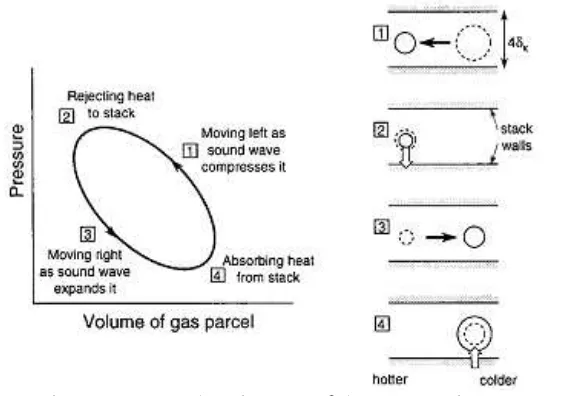
Figure 1.shows the cycle of refrigerator process or thermal pumping of thermoacoustic. Before thermoacoustic device is operated, the temperature on both
reservoirs are same. When thermoacoustic device starts operating, the oscillation of sound waves cause the gas packages in the stack move from cold reservoir to the hot reservoir (to the left). Adiabatic process occurs at step 1 (from 1 to 2) when the gas packages volume are compressed because of higher pressures in the near hot reservoir, so the temperature rises. As a result, gas package to be hotter than the stack wall nearby so the package gas releases thermal to the walls of the stack and the gas package volume shrinks, this process is an isothermal process that occurs in step 2 (from 2 to 3). Step 3 package gas moves back to the right because the right side has lower pressure (from 3 to 4), it is adiabatic process that is when the streched package volume gas (adiabatic) due to a lower pressure near the cold reservoir , so the temperature drops. Step 4 package of gas to be colder than the walls of the stack nearby, so the package gas absorbs thermal from the stack wall and fluffy (from 4 to 1). This cycle recurs then there is the temperature difference is large enough at the ends of the stack. Stack end wall space that is added by thermal hot reservoir while the end wall space that is taken the thermal into the cold reservoir. This process will stop when the sound source is turned off. Gas package is referred to in this discussion is a package of gas that are closest to the stack.7
Thermal penetration depth is a Must note, thermal penetration depth
k is the distance of thermal diffusion through the gas in the interval t = 1/πf withf is the frequency of sound waves. Thermal penetration depth depends on the gas thermal conductivity (k) and the gas density(ρ) as well, the thermal capacity per unit of the gas mass(cp) as8:f kg/m3), and the specific thermal per unit gass mass (cp = 1007 J/kg.K),the thermal
transfer in the cycle nearing isothermal.
This study uses a parallel cylinder stack diameter (1.50 ± 0.05) mm and a length of 8 cm. Stack material that used is of the cable sheathing is made of PVC (polyvinyl chloride). It was chosen because, stack used insulator material having a thermal conductivity low enough, besides that the PVC material is solid form so it is not easy to move and change the shape, and also is decreasing temperature in the operating of thermoacoustic refrigerator system using PVC stack.
Methods
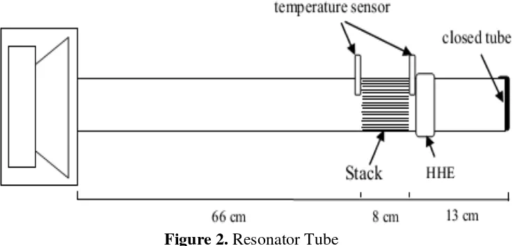
Resonator Tube
Resonator tubes is made of PVC pipe with length of 87 cm and a diameter in (5.25 ± 0.05) cm. Resonator tube consists of three parts (Figure 2), namely;
1. The part that is directly connected with a loudspeaker which has a length of 66 cm.
2. The part that contains the stack with a length of 8 cm.
3. Cover tubes length of 13 cm.
Stack PVC (Polyvinyl Chloride)
Stack PVC (polyvinyl chloride) is parallel cylinder is made from a single wire cable sheathing diameter (1.50 ± 0.05) mm that has already available form the cylinder so easy to use as stack. Cable sheathing that has already removed the copper wire is cut each 8 cm and placed parallel to the PVC pipe with diameter of 5.25 same as resonator tube, until met to form the diameter.
Jurnal Neutrino:Jurnal Fisika dan Aplikasinya,Vol. 9, No.2, April 2017 (p.32-38) [35]
Figure 3. Stack PVC (polyvinyl chlorida) from single wire cable sheathing diameter
(1.50 ± 0.05) mm
Figure 4. Stackis placedλ/20 from the closed end of the resonator tube.
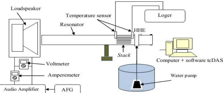
Figure 5. Schematic of thermoacoustic device series
Assembly and Operating Equipment Stack up to 8 cm with diameter 5.25 cm is placed 17 cm from the closed end of the resonator tube, measured from the midpoint of the stack length (Figure4).
AFG is set on the resonant frequency. TcDAS software in the computer is started, on the computer screen will be seen hot and cold temperature reservoir. Before the audio amplifier carries the signal to vibrate the loudspeaker, both of the reservoirs must be at the same temperature tolerance (maximum difference) of 0.2 ° C. Resonator tube must be closed without a hole. Making sure about that, the end of the pipe near the hot reservoir must be closed.
Complete series schematic entire thermoacustic system showed in Figure 5.
Once the thermoacoustic device is operated immediately available decreasing
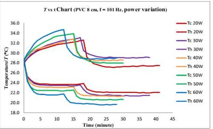
Figure 6. Variation of the loudspeaker input power to change the hot temperatures (Th), cold temperature (Tc)
Result and Discussion
Observation of the input power variation of sound source to the decreasing temperature has done on the best stack material that has been already obtained from previous research that is PVC cable sheathing materials length of 8 cm, and using the optimum resonance frequency that has already observed on the material that is (101.0 ± 0, 5) Hz. The experimental results transformation temperature on both of reservoir with input power variation of the sound source is showed in Figure 6.
Figure 6. shows that the optimum decreasing temperature depends on how much the loudspeaker power. From these results, the amount of the loudspeaker power
used on the stack PVC cable sheathing materials have the greatest decreasing temperature or optimum up to 19.6 °C or 9.0 °C relative to the initial temperature, which occurs in the greatest input power that is 60 watt. In general it can be said that the greater power that used it will be faster the achievement of optimum decreasing temperature, and conversely the smaller power that used it will be slower the achievement of optimum decreasing temperature.
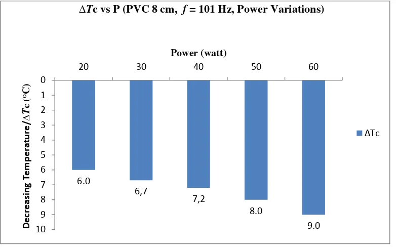
Here is a bar chart that shows decreasing temperature before the end after HHE water flowed toward the input power variation on the stack PVC cable sheathing material showed in Figure 7.
Table 1. Shows time taken before HHE flowed water to reach the optimum decreasing temperature to power variation
Power (watt)
t
before HHEflowed water (minutes)
ΔTcbefore HHEflowed water (°C)
20 16 4,3
30 15 4,7
40 13 5,4
50 12 6,2
Jurnal Neutrino:Jurnal Fisika dan Aplikasinya,Vol. 9, No.2, April 2017 (p.32-38) [37]
Gambar 7. Variation ofthe loudspeakerinput power toward decreasing temperature Figure 7.shows optimum decreasing
temperature depends on the amount of the loudspeaker power. Based on the picture shows clearly that the input power of the sound source takes effect on decreasing temperature namely 6.0 °C to 20 watt, 6.7 °C to 30 watt, 7.2 °C to 40 watt, 8.0 °C to 50 watt and 9.0 °C to the power of 60 watt. From the results can be concluded that the power of the sound source is directly proportional to the resulting of decreasing temperature. In other words, if the power used on the loudspeaker is bigger then the decreasing temperature that obtained is relatively greater, and vice versa if the power used is lower then the decreasing temperature that obtained is relatively smaller.
Conclusion
Thermoacustic refrigerator system performance depended on how much the loudspeaker power. The amount of the loudspeaker power that used on PVC stack had the optimum decreasing temperature that was obtained, it reached temperature19,6 °C or 9.0 °C relative to the initial temperature, which occured in the largest input power that was 60 watt and input frekuence was 101 Hz. The input power of the sound source is
decreasing temperature that obtained, in other words the increasing of input power obtains the greater decreasing temperature and also the faster optimum decreasing temperature in the thermoacousticrefrigerant system
Acknowledgment
The author want to say thanks to Thermoacoustic FMIPA UGM research group, IKIP PGRI Jember for supporting in this publication.
References
1. Jaworski AJ, Mao X. Development of thermoacoustic devices for power generation and refrigeration. Journal Power and Energy [Internet]. 2014 July [cited 2017 Feb 28];227(7):762-782. Availablefrom:http://journals.sagepub.co m/doi/pdf/10.1177/0957650913493622 2. Marx D, Mao X, Jaworski AJ. Acoustic
coupling between the loudspeaker and the resonator in a standing-wave thermoacoustic device.Applied Acoustics. 2006:67(5):402-419.
doi:10.1016/j.apacoust.2005.08.001 3. Panara KS, Patel AM, Patel NS, Patel JD.
Setup. International Journal of Mechanical Engineering and Technology (IJMET) [Internet]. 2015 Nov [cited 2017 Feb
24];6(11):1-15. Available
from:http://www.iaeme.com/MasterAdmi n/UploadFolder/IJMET_06_11_001/IJME T_06_11_001.pdf
4. Tang K, Chen GB, Jin T, Bao R, Kong B, Qiu LM. Influence of resonance tube length on performance of thermoacousically driven pulse tube refrigerator. Elsevier International Journal of Cryogenics. 2005:45(3):185-191. doi:10.1016/j.cryogenics.2004.10.00 5. Tijani MEH, Zeegers JCH, De Waele
ATAM. Design of Thermoacoustic Refrigerators. Elsevier International Journal of Cryogenics. 2002:42(1):49-57. doi:10.1016/S0011-2275(01)00179-5
6. Ghazali NM, Anwar M, Settar NH. Thermoacoustic Cooling with No Refrigerant. International Journal of Technology [Internet]. 2011 [cited 2017 Feb 25]:2(3):234-241. Available from: http://www.ijtech.eng.ui.ac.id/index.php/j ournal/article/view/72
7. Russell DA, Weibull P. Tabletop Thermoacoacoustic Refrigerator for Demonstrations. American Journal of Physics. 2002:70(12):1231-1233. doi:10.1119/1.1485720
8. Nsofor EC, Celik S, Wang X. Experimental Study On the Heat Transfer at the Heat Exchanger of the Thermoacoustic Refrigerating System. 2007:27(14-15):2435-2442.