UNIVERSITAS
UDAYANA
145
An Experimental To Investigate The Effect Nozzle Angle An Position Of
Water Turbin For Obtaining Higest Rotation
Lie Jasa1 , IGA Raka Agung1, I Putu Ardana1, Ardyono Priyadi2 and Mauridhi Her y Purnomo2 1
Electrical Engineering Department,Udayana University, Bali, Indonesia 2
Electrical Engineering De partme nt, Sepuluh Nopember Institute of Technology, Sura baya, Indonesia E-mail : [email protected]
Abstract
Water is a key issue for an alternative renewable en ergy source has environmentally friendly and very large potential to solve the world's energy crisis. Water energy can be converted into mechanical energy by means a micro-hydro turbine. Therefore, the specific turbine is required to obtain the highest efficiency. This p aper proposes the experimental to investigate the significant p arameters for obtainin g th e highest efficiency turbine. These parameters, angle and position nozzle, radius, blades and rotation, are investigated by conducting experiments using mini turbine models. The angle a nd position nozzle is adju stable to obtain the highest speed rotation of turbine. The characteristics of the mini turbine model are explained as follows: outer radius is 0.5 m, inner radius is 0.4 m, width 0.12 m, th e number o f blades 32, volume 0.294 litre blades. The experiment result shows that the highest rotation is obtained by 10 degrees for nozzle position and 35 degrees for incidence angle. The best position of nozzle at blades number 2 produces the speed of turbine 68.31 666667 rpm.
Key words : Nozzle, turbine, water wh eel, en erg y
1. Introduction
The energy plays an important role for population in the world. The energy demand is significantly increases every year but the energy resource is limited and decreases especially conventional energy. Hydropower is one of clea n energy resourc es in the world. It is also the most reliable and effectively cost renewable energy resource among the others. Small hydropower schemes are getting increasingly popular because of its simplicity design, ease in operation, and lower environment of heavy construction in comparison to large hydropower schemes[1]. Conventional highly efficient low head hydraulic turbines, such as Kaplan, become economically unviable because of the large size of the turbine required for very low head installations, requirement of special flow control mechanism and the risk the impose on the ecology especially on fish, trash and sediment transport.[1],[2],[3].
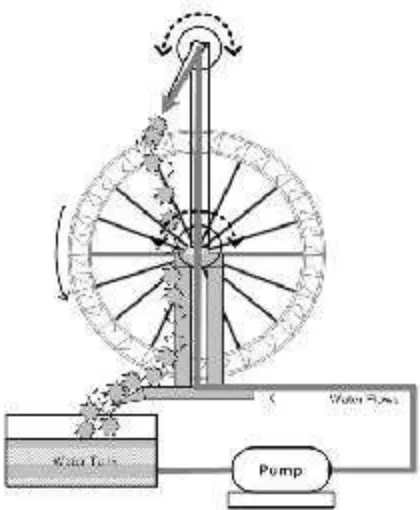
water wheel is a simple machine, cheap and has long been known in the community to generate the energy. Water wheels were used as a primary source of power in ancient times. Water wheels are simple machines usually made of wood or steel with blades fixed at regular interval around their circumference. The blades are pushed by the water tangentially around the wheel. The thrust produced by the water on the blades produces torque on the shaft and as result the wheel revolves.[1],[4],[5]. Four commonly used water wheels models are overshot, undershot, breast shot and stream wheels. Overshot waterwheels are driven by potential energy created by the accumulated water in the buckets of the wheel. Water flows at the top of the wheel and fills into the buckets attached on the periphery of the wheel.[1],[6],[7],[8],[9].
146
the initial model of the experiment [10],[11],[12]. In this paper proposed how to get the maximum RPM of water wheels based on the influenced of the position nozzle and the incidence nozzle.2 The overshot water wheel model 2.1. Hydraulics power theory
Theorem of water flow is used to determine the amount of energy that can be generated from the flowing water. The total extractable hydraulic power from the flowing wa ter is given by the expression of Pin =
3
), g is the acceleration due to gravity (9,81m/s2), Q is the volumetric water flow rate (m3/s) and H is the difference in total energy line upstream and
the number of revolutions N at the given load in revolutions per minute (RPM) of the wheel as : force F of water striking the blades of the water wheel (N) and the moment arm length (m) which, in this case, is the radius of the pulley r. Force is equal to the differences in the mass obtained from the two load cells time the acceleration due to gravi
out
the power of outp out /
Pin x 100%
2.2 Overshot water wheel prototype
Water wheels model is created specially to variety of the nozzle position and the angle nozzle that can be adjusted mechanically. This model is different from the water wheel of rea l installation. Water wheel model is pla nned rotating clockwise direction with 32 blades and 11.25o space of blades. The bla des shape is triangular and placed around circumference wheel. The position of arm nozz le is variety multiples 11.25o and The bla des of wheel are marked of
is ma de longer than the radius of wheels.
Figure 1. Overshot water wheel nozzle angle design
148
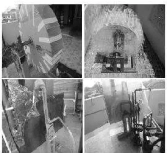
Figure 3. Overshot water wheel nozzle angle model2.3. Nozzle angle position
angle is less than 90o. Nozzle position is alwa ys on the top of wheel and nozzle direction is always toward into wheel blades. The design of the position arm nozzle is shown in Figure 4.
Figure 4. The position of arm nozzle
The length of arm nozzle must be the longer than radius of the wheel. The nozzle position is always outside of radius of the wheel and centre point wheel the same with point butt of self. The magnitude -10o, 0o, 10o and 20o
Figure 5. Position of nozzle engles
3. Experiment Result
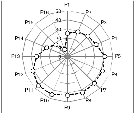
The arm nozzle can be occupied the position at P1 until P17.The angle of arm nozzle is increased every 5o with midpoint at P9 (angle 0o). Figure 4 shows that from the mid point to right the negative sign and to left the positive sign. The experiments were performed by placing the arm nozzle at point P1, nozzle in a parallel position with the arm nozzle. The system is run, if the wheel is spinning observed and RPM measured with tachometer. According results of observation of wheel, The wheel does not rotate at position P1, P2, P3, P4. Wheel starts to spinning at P5 with the RPM 40.758 until 58.425 RPM at P16. The graph results of measurement RPM of the position of angle N ozzle is shown in Figure 6.
Figure 6. The RPM of water wheel based on position nozzle
150
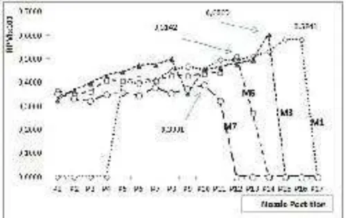
Experiments with the angle nozzle, by placing the arm of nozzle on t he position angle nozzle arm at P1 until P17. The next step is adjusted the value of angle nozz le between the nozzle arm with the nozzle itself each angle -10o, 0o, 10o, 20o. nozzle position on top of blades with angle nozzle the sa me with 0o is meaning the nozzle and nozzle arm is parallel. The next step is repeated for a junction angle 10o, 10o, 20o. The measurement of the RPM results with change the angle nozzle ca n be seen in Figure 7. With the turbine width 12 cm, length of nozzle 8 cm and variety of angle nozzle with -10o, 0o, 10o and 20o, the RPM measurement of water wheels is shown in figure 7. The principle in this experiment is measurement RPM of water wheel is base on the changes of the magnitude of angle nozzle. Measurement of the angle -10o , will be produces the highest RPM at 79.1333 and the lowest at 22,458. The change of the nozzle a ngle affects significantly on P13 until P17. The results of the experiment of the change of the nozzle angle is influence significant of the RPM of water wheel only occur at an angle 20o until 35o. Detail is shown at Figure 8.
Figure 7. The RPM of weterwheel base on nozzle angles
Figure 8. RPM of overshot water wheel nozzle angle position
4. Conclusion
The RPM of water wheel is produced increase when nozzle position at the range of angle 5o until 35o. The highest RPM of water wheels is obtained at 68.316667 at position angle 30o (P15) or at blades number 2. The highest average RPM of the water wheel is at 45.44643 obtained at nozzle
angle 10o position (P11). This indicates that the waterwheel is installed on the location, the position of nozzle can be set that the waterwheel produces RPMs closer to the ma ximum. The changes of nozzle direction is resulted the highest of RPM at 79.13333 at an angle of 35o (P15) at nozzle angle at -10o . of channel width on flexible rubber blade water wheel performance,” Renewable Energy, vol. 52, pp. 1–7, Apr. 2013.
[2] T. Sakurai, H. Funato, and S. Ogasawara, “Fundamental characteristics of test facility for micro hydroelectric power generation system,” presented at the International Conference on Electrical Machines and Systems, 2009. ICEMS 2009, 2009, pp. 1 –6.
[3] L. Wang, D.-J. Lee, J.-H. Liu, Z.-Z. Chen, Z.-Y. Kuo, H.-Y. Jang, J.-J. You, J.-T. Tsai, M.-H. Tsa i, W.-T. Lin, and Y.-J. Lee, “Installation and practical operation of the first micro hydro power system in Taiwan using irrigation water in an agriculture canal,” in 2008 IEEE Power and Energy Society General Meeting - Conversion a nd Delivery of Electrical Energy in the 21st Century, 2008, pp. 1 –6.
[4] A. Zaman and T. Khan, “Design of a Water Wheel For a Low H ead Micro Hydropower System,” Journal Basic Science And Technology, vol. 1(3), pp. 1–6, 2012.
[5] G. Muller, Water Wheels as a Power Source. 1899.
[6] M. Denny, “The Efficiency of Overshot a nd Undershot Waterwheels,” European Journal of Physics, vol. 25, pp. 193–202, 2003.
[7] K. H. Fasol, “A short history of hydropower control,” IEEE Control Systems, vol. 22, no. 4, pp. 68 – 76, Aug. 2002.
[8] L. A. HAIMERL, “The Cross-Flow Turbine.”
[9] C. A. Mockmore and F. Merryfield, “The Banki Water Turbine,” Bulletin Series no.25, Feb. 1949. [10] L. Jasa, P. Ardana, and I. N. Setiawan, “Usaha Mengatasi Krisis Energi Dengan Memanfaatkan
Aliran Pangkung Sebagai Sumber Pembangkit Listrik Alternatif Bagi Masyaraka t Dusun Gambuk –Pupuan-Tabanan,” in Proceding Seminar Nasional Teknologi Industri XV, ITS, Surabaya, 2011, pp. B0377–B0384.
[11] L. Jasa, A. Priyadi, and M. Hery P, “PID Control for Micro Hydro Power Plants Base on Neural Network,” in Proceding Modeling, Identification and Control (AsiaMIC 2012), Phuket, Thailand, 2012.