Livingston , E., Scavuzzo, R. J. “Pressure Vessels”
The Engineering Handbook.
Ed. Richard C. Dorf
Boca Raton: CRC Press LLC, 2000
9
Pressure Vessels
9.1 Design Criteria
Design Loads • Materials • Allowable Stress 9.2 Design Formulas
9.3 Opening Reinforcement
Earl Livingston
Babcock and Wilcox Company, Retired
Rudolph J. Scavuzzo
University of Akron
Pressure vessels used in industry are leak-tight pressure containers, usually cylindrical or spherical in shape, with different head configurations. They are usually made from carbon or stainless steel and assembled by welding. Early operation of pressure vessels and boilers resulted in numerous explosions, causing loss of life and considerable property damage. Some 80 years ago, the American Society of Mechanical Engineers formed a committee for the purpose of establishing minimum safety rules of construction for boilers. In 1925 the committee issued a set of rules for the design and construction of unfired pressure vessels. Most states have laws mandating that these Code rules be met. Enforcement of these rules is accomplished via a third party employed by the state or the insurance company. These Codes are living documents in that they are constantly being revised and updated by committees composed of individuals knowledgeable on the subject. Keeping current requires that the revised Codes be published every three years with addendas issued every year. This chapter covers a very generalized approach to pressure vessel design based on the ASME Boiler and Pressure Vessel Code, Section VIII, Division 1: Pressure Vessels.
9.1 Design Criteria
The Code design criteria consist of basic rules specifying the design method, design load, allowable stress, acceptable material, and fabricationinspection certification requirements for vessel construction.The design method known as "design by rule" uses design pressure,
allowable stress, and a design formula compatible with the geometry of the part to calculate the minimum required thickness of the part. This procedure minimizes the amount of
analysis required to ensure that the vessel will not rupture or undergo excessive distortion. In conjunction with specifying the vessel thickness, the Code contains many construction details that must be followed. Where vessels are subjected to complex loadings such as cyclic, thermal, or localized loads, and where significant discontinuities exist, the Code requires a more rigorous analysis to be performed. This method is known as the "design by analysis" method. A more complete background of both methods can be found in Bernstein, 1988.
The ASME Code [1994] is included as a standard by the American National Standards Institute ( ANSI). The American Petroleum Institute (API) has also developed codes for low-pressure storage tanks, and these are also part of the ANSI standards. The ASME Boiler and Pressure Vessel Code has been used worldwide, but many other industrialized countries have also developed boiler and pressure vessel codes. Differences in these codes sometimes cause difficulty in international trade.
Design Loads
The forces that influence pressure vessel design are internal/external pressure; dead loads due to the weight of the vessel and contents; external loads from piping and attachments, wind, and earthquakes; operating-type loads such as vibration and sloshing of the contents; and startup and shutdown loads. The Code considers design pressure, design temperature, and, to some extent, the influence of other loads that impact the circumferential (or hoop) and longitudinal stresses in shells. It is left to the designer to account for the effect of the remaining loads on the vessel. Various national and local building codes must be consulted for handling wind and earthquake loadings.
Materials
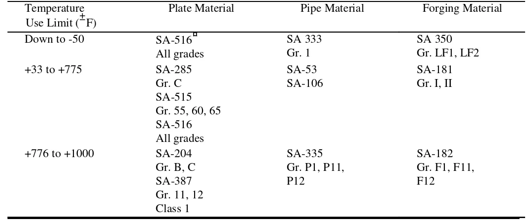
The materials to be used in pressure vessels must be selected from Code-approved material specifications. This requirement is normally not a problem since a large catalogue of tables listing acceptable materials is available. Factors that need to be considered in picking a suitable table are:
Cost
Fabricability
Service condition (wear, corrosion, operating temperature) Availability
Strength requirements
Table 9.1 Acceptable Pressure Vessel Materials
Temperature Use Limit (±F)
Plate Material Pipe Material Forging Material
Down to -50 SA-516¤
Note:SA is a classification of steel used in the ASME Boiler and Pressure Vessel Code.
Allowable Stress
The allowable stress used to determine the minimum vessel wall thickness is based on the material tensile and yield properties at room and design temperature. When the vessel operates at an elevated temperature, the creep properties of the material must also be
considered. These properties are adjusted by design factors which limit the hoop membrane stress level to a value that precludes rupture, and excessive elastic or plastic distortion and creep rupture. Table 9.2 shows typical allowable stresses for several carbon steels commonly used for unfired pressure vessels.
Table 9.2 Typical Allowable Stresses for Use in Pressure Vessel Design
900 12 000
The design formulas used in the "design by rule" method are based on the principal stress theory and calculate the average hoop stress. The principal stress theory of failure states that failure occurs when one of the three principal stresses reaches the yield strength of the material. Assuming that the radial stress is negligible, the other two principal stresses can be determined by simple formulas based on engineering mechanics.
The Code recognizes that the shell thickness may be such that the radial stress may not be negligible, and adjustments have been made in the appropriate formulas. Table 9.3 shows various formulas used to calculate the wall thickness for numerous pressure vessel
geometries.
Table 9.3 Code Formulas for Calculation of Vessel Component Thickness
Cylindrical shell t = SE ¡ 0:6PP R
Hemispherical head or spherical shell t = 2SE ¡ 0:2PP R
2:1 ellipsoidal head t = 2SE ¡ 0:2PP D
Flanged and dished head t = 1:77P L
2SE ¡ 0:2P
Flat head t = dp CP=SE
where
t = Minimum required thickness (in.)
P = Design pressure (psi)
R = Inside radius (in.)
S = Allowable stress (psi)
D = Inside diameter (in.)
L = Inside spherical crown radius (in.)
E = Weld joint efficiency factor, determined by joint location and degree of examination
9.3 Opening Reinforcement
Vessel components are weakened when material is removed to provide openings for nozzles or access. High stress concentrations exist at the opening edge and decrease radially
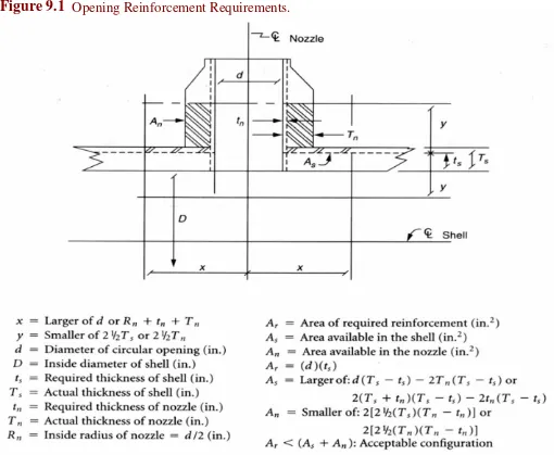
outward from the opening, becoming negligible beyond twice the diameter from the center of the opening. To avoid failure in the opening area, compensation or reinforcement is required. Some ways in which this can be accomplished are: (a) increase the vessel wall thickness, (b) increase the wall thickness of the nozzle, or (c) use a combination of extra shell and nozzle thickness. The Code procedure is to relocate the removed material to an area within an effective boundary around the opening. Figure 9.1 shows the steps necessary to reinforce an opening in a pressure vessel. Numerous assumptions have been made with the intent of simplifying the general approach.
Figure 9.1 Opening Reinforcement Requirements.
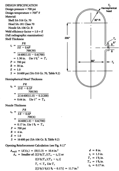
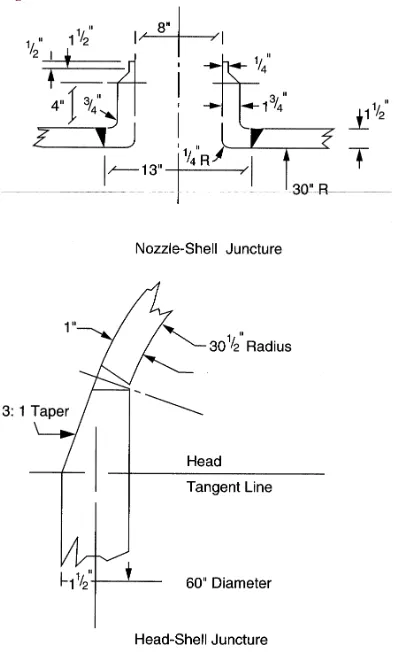
The example shown in Fig. 9.2 uses the design approach indicated by the Code to perform a simple sizing calculation for a typical welded carbon steel vessel. Figure 9.3 shows a typical shell-nozzle juncture and head-shell juncture which meet the code requirements. Design
Figure 9.2 Sample vessel calculation.
Figure 9.3 Fabrication details.
Defining Terms
Code: The complete rules for construction of pressure vessels as identified in ASME Boiler and Pressure Vessel Code, Section VIII, Division 1, Pressure Vessels.
Construction: The complete manufacturing process, including design, fabrication,
inspection, examination, hydrotest, and certification. Applies to new construction only.
Hoop membrane stress: The average stress in a ring subjected to radial forces uniformly distributed along its circumference.
Longitudinal stress: The average stress acting on a cross section of the vessel.
Pressure vessel: A leak-tight pressure container, usually cylindrical or spherical in shape, with pressure usually varying from 15 psi to 5000 psi.
Stress concentration: Local high stress in the vicinity of a material discontinuity such as a change in thickness or an opening in a shell.
Weld efficiency factor: A factor which reduces the allowable stress. The factor depends on the degree of weld examination performed during construction of the vessel.
References
American Society of Mechanical Engineers. 1994. ASME Boiler and Pressure Vessel Code,
Section VIII Division 1, Pressure Vessels. ASME, New York.
Bednar, H. H. 1981. Pressure Vessel Design Handbook. Van Nostrand Reinhold, New York.
Bernstein, M. D. 1988. Design criteria for boiler and pressure vessels in the U.S.A. ASME J. P
−443.
Jawad, M. H. and Farr, J. R. 1989. Structural Analysis and Design of Process Equipment,
2nd ed. John Wiley & Sons, New York.
Further Information
Each summer, usually in June, the Pressure Vessels and Piping Division of the American Society of Mechanical Engineers organizes an annual meeting devoted to pressure vessel technology. Usually 300 to 500 papers are presented, many of which are published by ASME in booklets called special publications. Archival papers are also published in the
Journal of Pressure Vessel Technology.
Research for ASME Boiler and Pressure Code work is often conducted by the Pressure Vessel Research Council (PVRC). This research is normally published in Welding Research Council bulletins . These bulletins, which number about 400, are an excellent documentation of major research contributions in the field of pressure vessel technology. The Electric