Database
Fundamentals
Neeraj Sharma, Liviu Perniu, Raul F. Chong, Abhishek Iyer, Chaitali Nandan,
Adi-Cristina Mitea, Mallarswami Nonvinkere, Mirela Danubianu
A book for the community by the community
First Edition (November 2010)
© Copyright IBM Corporation 2010. All rights reserved.
IBM Canada
8200 Warden Avenue Markham, ON L6G 1C7 Canada
Notices
This information was developed for products and services offered in the U.S.A.
IBM may not offer the products, services, or features discussed in this document in other countries. Consult your local IBM representative for information on the products and services currently available in your area. Any reference to an IBM product, program, or service is not intended to state or imply that only that IBM product, program, or service may be used. Any functionally equivalent product, program, or service that does not infringe any IBM intellectual property right may be used instead. However, it is the user's responsibility to evaluate and verify the operation of any non-IBM product, program, or service.
IBM may have patents or pending patent applications covering subject matter described in this document. The furnishing of this document does not grant you any license to these patents. You can send license inquiries, in writing, to:
IBM Director of Licensing IBM Corporation
North Castle Drive Armonk, NY 10504-1785 U.S.A.
For license inquiries regarding double-byte character set (DBCS) information, contact the IBM Intellectual Property Department in your country or send inquiries, in writing, to:
Intellectual Property Licensing Legal and Intellectual Property Law IBM Japan, Ltd.
3-2-12, Roppongi, Minato-ku, Tokyo 106-8711
The following paragraph does not apply to the United Kingdom or any other country where such provisions are inconsistent with local law: INTERNATIONAL BUSINESS MACHINES CORPORATION PROVIDES THIS PUBLICATION "AS IS" WITHOUT WARRANTY OF ANY KIND, EITHER EXPRESS OR IMPLIED, INCLUDING, BUT NOT LIMITED TO, THE IMPLIED WARRANTIES OF NON-INFRINGEMENT, MERCHANTABILITY OR FITNESS FOR A PARTICULAR PURPOSE. Some states do not allow disclaimer of express or implied warranties in certain transactions, therefore, this statement may not apply to you.
This information could include technical inaccuracies or typographical errors. Changes are periodically made to the information herein; these changes will be incorporated in new editions of the publication. IBM may make improvements and/or changes in the product(s) and/or the program(s) described in this publication at any time without notice.
Any references in this information to non-IBM Web sites are provided for convenience only and do not in any manner serve as an endorsement of those Web sites. The materials at those Web sites are not part of the materials for this IBM product and use of those Web sites is at your own risk.
The licensed program described in this document and all licensed material available for it are provided by IBM under terms of the IBM Customer Agreement, IBM International Program License Agreement or any equivalent agreement between us.
Any performance data contained herein was determined in a controlled environment. Therefore, the results obtained in other operating environments may vary significantly. Some measurements may have been made on development-level systems and there is no guarantee that these measurements will be the same on generally available systems. Furthermore, some measurements may have been estimated through extrapolation. Actual results may vary. Users of this document should verify the applicable data for their specific environment.
Information concerning non-IBM products was obtained from the suppliers of those products, their published announcements or other publicly available sources. IBM has not tested those products and cannot confirm the accuracy of performance, compatibility or any other claims related to non-IBM products. Questions on the capabilities of non-IBM products should be addressed to the suppliers of those products.
All statements regarding IBM's future direction or intent are subject to change or withdrawal without notice, and represent goals and objectives only.
This information contains examples of data and reports used in daily business operations. To illustrate them as completely as possible, the examples include the names of individuals, companies, brands, and products. All of these names are fictitious and any similarity to the names and addresses used by an actual business enterprise is entirely coincidental.
COPYRIGHT LICENSE:
This information contains sample application programs in source language, which illustrate programming techniques on various operating platforms. You may copy, modify, and distribute these sample programs in any form without payment to IBM, for the purposes of developing, using, marketing or distributing application programs conforming to the application programming interface for the operating platform for which the sample programs are written. These examples have not been thoroughly tested under all conditions. IBM, therefore, cannot guarantee or imply reliability, serviceability, or function of these programs. The sample programs are provided "AS IS", without warranty of any kind. IBM shall not be liable for any damages arising out of your use of the sample programs.
References in this publication to IBM products or services do not imply that IBM intends to make them available in all countries in which IBM operates.
Trademarks
IBM, the IBM logo, and ibm.com are trademarks or registered trademarks of International Business Machines Corp., registered in many jurisdictions worldwide. Other product and service names might be trademarks of IBM or other companies. A current list of IBM trademarks is available on the Web at
Java and all Java-based trademarks are trademarks of Sun Microsystems, Inc. in the United States, other countries, or both.
Microsoft and Windows are trademarks of Microsoft Corporation in the United States, other countries, or both.
Table of Contents
Preface ... 15
Who should read this book? ... 15
How is this book structured? ... 15
A book for the community ... 15
Conventions ... 15
What’s next? ... 16
About the Authors ... 17
Contributors ... 19
Acknowledgements ... 21
Chapter 1 - Databases and information models ... 23
1.1 What is a database? ... 23
1.2 What is a database management system? ... 23
1.2.1 The evolution of database management systems ... 24
1.3 Introduction to information models and data models ... 26
1.4 Types of information models ... 27
1.4.1 Network model ... 28
1.4.2 Hierarchical model ... 28
1.4.3 Relational model ... 29
1.4.4 Entity-Relationship model ... 30
1.4.5 Object-relational model ... 31
1.4.6 Other data models ... 32
1.5 Typical roles and career path for database professionals ... 32
1.5.1 Data Architect ... 32
1.5.2 Database Architect ... 32
1.5.3 Database Administrator (DBA) ... 33
1.5.4 Application Developer ... 34
1.6 Summary ... 34
1.7 Exercises ... 35
1.8 Review questions ... 35
Chapter 2 – The relational data model ... 37
2.1 Relational data model: The big picture ... 37
2.2 Basic concepts ... 38
2.3 Relational data model constraints ... 44
2.3.1 Entity integrity constraint ... 44
2.3.2 Referential integrity constraint ... 45
2.3.3 Semantic integrity constraints ... 46
2.4.1 Union ... 49
2.5.1 Tuple-oriented relational calculus ... 58
2.5.2 Domain-oriented relational calculus ... 59
2.6 Summary ... 60
2.7 Exercises ... 60
2.8 Review questions ... 62
Chapter 3 – The conceptual data model ... 65
3.1 Conceptual, logical and physical modeling: The big picture ... 65
3.2 What is a model? ... 67
3.2.1 Data model ... 67
3.2.2 Database model ... 67
3.2.3 Conceptual data model concepts ... 68
3.3 A case study involving a Library Management System - Part 1 of 3 ... 77
3.3.1 Developing the conceptual model ... 77
3.4 Summary ... 85
3.5 Exercises ... 85
3.6 Review questions ... 85
Chapter 4 – Relational Database Design ... 89
4.1 The problem of redundancy ... 89
4.1.1 Insertion Anomalies ... 90
4.1.2 Deletion Anomalies ... 90
4.1.3 Update Anomalies ... 90
4.2. Decompositions ... 91
4.3. Functional Dependencies ... 92
4.4 Properties of Functional Dependencies ... 94
4.4.1 Armstrong’s Axioms ... 94
4.4.2 Computing the closure set of attributes ... 95
4.4.3 Entailment ... 96
4.5 Normal Forms ... 96
4.5.1 First Normal Form (1NF) ... 96
4.5.2 Second Normal Form (2NF) ... 98
4.5.3 Third Normal Form (3NF) ... 99
4.5.4 Boyce-Codd Normal Form (BCNF) ... 100
4.6 Properties of Decompositions ... 101
4.6.1 Lossless and Lossy Decompositions ... 102
4.6.2 Dependency-Preserving Decompositions ... 103
4.8 Synthesis of 3NF schemas ... 105
4.9 3NF decomposition ... 106
4.10 The Fourth Normal Form (4NF) ... 106
4.10.1 Multi-valued dependencies ... 107
4.11 Other normal forms ... 108
4.12 A case study involving a Library Management System - Part 2 of 3 ... 108
4.13 Summary ... 111
4.14 Exercises ... 112
4.15 Review questions ... 112
Chapter 5 – Introduction to SQL ... 115
5.1 History of SQL ... 115
5.2 Defining a relational database schema in SQL ... 116
5.2.1 Data Types... 116
5.2.2 Creating a table ... 117
5.2.3 Creating a schema ... 120
5.2.4 Creating a view ... 121
5.2.5 Creating other database objects ... 121
5.2.6 Modifying database objects ... 121
5.2.7 Renaming database objects ... 122
5.3 Data manipulation with SQL ... 122
5.3.1 Selecting data ... 122
5.5 Union, intersection, and difference operations ... 128
5.5.1 Union ... 129
5.7.1 Sub-queries returning a scalar value ... 133
5.7.2 Sub-queries returning vector values ... 133
5.7.3 Correlated sub-query ... 133
5.7.4 Sub-query in FROM Clauses ... 134
5.8 Mapping of object-oriented concepts to relational concepts ... 134
5.10 A case study involving a Library Management System - Part 3 of 3 ... 135
5.9 Summary ... 139
5.10 Exercises ... 140
Chapter 6 – Stored procedures and functions ... 143
6.1 Working with IBM Data Studio ... 143
6.1.1 Creating a project ... 144
6.2 Working with stored procedures ... 146
6.2.1 Types of procedures ... 147
6.2.2 Creating a stored procedure ... 148
6.2.3 Altering and dropping a stored procedure ... 152
6.3 Working with functions ... 153
6.3.1 Types of functions ... 153
6.3.2 Creating a function ... 154
6.3.3 Invoking a function ... 155
6.3.4 Altering and dropping a function ... 156
6.4 Summary ... 157
6.5 Exercises ... 157
6.6 Review Questions ... 157
Chapter 7 – Using SQL in an application ... 161
7.1 Using SQL in an application: The big picture ... 161
7.2 What is a transaction? ... 162
7.3 Embedded SQL ... 163
7.3.1 Static SQL ... 163
7.3.2 Dynamic SQL ... 168
7.3.3 Static vs. dynamic SQL ... 172
7.4 Database APIs ... 173
7.4.1 ODBC and the IBM Data Server CLI driver ... 173
7.4.2 JDBC ... 175
7.5 pureQuery ... 176
7.5.1 IBM pureQuery Client Optimizer ... 179
7.6 Summary ... 179
7.7 Exercises ... 180
7.8 Review Questions ... 180
Chapter 8 – Query languages for XML ... 183
8.1 Overview of XML... 183
8.1.1 XML Elements and Database Objects ... 183
8.1.2 XML Attributes ... 185
8.1.3 Namespaces ... 186
8.1.4 Document Type Definitions ... 187
8.1.5 XML Schema ... 188
8.2 Overview of XML Schema ... 189
8.2.1 Simple Types ... 189
8.2.2 Complex Types ... 191
8.2.3 Integrity constraints ... 192
8.2.4 XML Schema evolution ... 193
8.3 XPath ... 194
8.3.1 The XPath data model ... 194
8.3.3 Path Expressions ... 196
8.3.4 Advanced Navigation in XPath ... 196
8.3.5 XPath Semantics ... 196
8.3.6 XPath Queries ... 198
8.4 XQuery ... 199
8.4.1 XQuery basics ... 200
8.4.2 FLWOR expressions ... 200
8.4.3 Joins in XQuery ... 201
8.4.4 User-defined functions ... 202
8.4.5 XQuery and XML Schema ... 202
8.4.6 Grouping and aggregation ... 202
8.4.7 Quantification ... 204
8.5 XSLT ... 204
8.6 SQL/XML ... 206
8.6.1 Encoding relations as XML Documents ... 206
8.6.2 Storing and publishing XML documents ... 207
8.6.3 SQL/XML Functions ... 207
8.7 Querying XML documents stored in tables ... 211
8.8 Modifying data ... 212
8.8.1 XMLPARSE ... 212
8.8.2 XMLSERIALIZE ... 213
8.8.3 The TRANSFORM expression ... 213
8.9 Summary ... 214
8.10 Exercises ... 215
8.11 Review questions ... 215
Chapter 9 – Database Security ... 221
9.1 Database security: The big picture ... 221
9.1.1 The need for database security ... 222
9.1.2 Access control ... 224
9.1.3 Database security case study ... 225
9.1.4 Views ... 231
9.1.5 Integrity Control ... 231
9.1.6 Data encryption ... 231
9.2 Security policies and procedures ... 232
9.2.1 Personnel control ... 232
9.2.2 Physical access control ... 232
9.3 Summary ... 233
9.4 Exercises ... 233
9.5 Review Questions ... 233
Chapter 10 – Technology trends and databases ... 235
10.1 What is Cloud computing? ... 235
10.1.1 Characteristics of the Cloud ... 236
10.1.2 Cloud computing service models ... 237
10.1.3 Cloud providers ... 237
10.1.5 Databases and the Cloud ... 242
10.2 Mobile application development ... 243
10.2.1 Developing for a specific device ... 244
10.2.2 Developing for an application platform ... 245
10.2.3 Mobile device platform ... 246
10.2.4 Mobile application development platform ... 247
10.2.5 The next wave of mobile applications ... 248
10.2.6 DB2 Everyplace ... 248
10.3 Business intelligence and appliances ... 249
10.4 db2university.com: Implementing an application on the Cloud (case study)... 249
10.4.1 Moodle open source course management system ... 250
10.4.2 Enabling openID sign-in... 253
10.4.3 Running on the Amazon Cloud ... 254
10.4.4 Using an Android phone to retrieve course marks ... 255
10.5 Summary ... 256
Appendix A – Solutions to review questions ... 259
Appendix B – Up and running with DB2 ... 264
B.1 DB2: The big picture ... 264
B.2 DB2 Packaging ... 265
B.2.1 DB2 servers ... 265
B.2.2 DB2 Clients and Drivers ... 266
B.3 Installing DB2 ... 267
B.3.1 Installation on Windows... 267
B.3.2 Installation on Linux ... 268
B.4 DB2 tools ... 268
B.4.1 Control Center ... 268
B.4.2 Command Line Tools ... 270
B.5 The DB2 environment ... 273
B.6 DB2 configuration ... 274
B.7 Connecting to a database ... 275
B.8 Basic sample programs ... 276
Preface
Keeping your skills current in today's world is becoming increasingly challenging. There are too many new technologies being developed, and little time to learn them all. The DB2® on Campus Book Series has been developed to minimize the time and effort required to learn many of these new technologies.
This book helps new database professionals understand database concepts with the right blend of breadth and depth of information.
Who should read this book?
This book is tailored for new database enthusiasts, application developers, database administrators, and anyone with an interest in the subject and looking to get exposure such as university students and new graduates.
How is this book structured?
This book is divided into chapters, starting with the basic database concepts and information models in Chapter 1. Chapter 2 covers relational data models. Chapter 3 and 4 explain conceptual modeling and relational database design. In Chapters 5, 6 and 7 the focus is geared towards SQL. Chapter 8 highlights XML data storage and retrieval via SQL and XQuery. Chapter 9 addresses database security aspects. The book then concludes with an overview of various other key technologies and relevant applications that are increasingly popular in the industry today.
Exercises and review questions can be found with most chapters. The solutions have been provided in Appendix A.
A book for the community
This book was created by a community of university professors, students, and professionals (including IBM employees). Members from around the world have participated in developing this book. The online version of this book is released to the community at no charge. If you would like to provide feedback, contribute new material, improve existing material, or help with translating this book to another language, please
send an email of your planned contribution t
“Database fundamentals book feedback”.
Conventions
Many examples of commands, SQL statements, and code are included throughout the book. Specific keywords are written in uppercase bold. For example: A NULL represents an unknown state. Commands are shown in lowercase bold. For example: The dir
upper case bold. For example: Use the SELECT statement to retrieve information from a table.
Object names used in our examples are shown in bold italics. For example: The flights
table has five columns.
Italics are also used for variable names in the syntax of a command or statement. If the variable name has more than one word, it is joined with an underscore. For example:
CREATE TABLE table_name
What’s next?
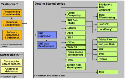
We recommend that you review the following books in this book series for more details about related topics:
Getting started with DB2 Express-C
Getting started with InfoSphere Data Architect Getting started with data warehousing
Getting started with DB2 application development
The following figure shows all the different eBooks in the DB2 on Campus book series
available free at
About the Authors
Neeraj Sharma is a senior IT specialist at the Dynamic Warehousing Center of Competency, IBM India Software Labs. His primary role is design, configuration and implementation of large data warehouses across various industry domains; implementation of custom proof of concept (POC) exercises, and execution of performance benchmarks at customer's request. He holds a bachelor’s degree in electronics and communication engineering and a master’s degree in software systems.
Liviu Perniu is an Associate Professor in the Automation Department at Transilvania University of Brasov, Romania, teaching courses in the area of Data Requirements, Analysis, and Modeling. He is an IBM 2006 Faculty Award recipient as part of the Eclipse Innovation Awards program.
Raul F. Chong is the DB2 on Campus program manager based at the IBM Toronto Laboratory, and a DB2 technical evangelist. His main responsibility is to grow the DB2 community around the world. Raul joined IBM in 1997 and has held numerous positions in the company. As a DB2 consultant, Raul helped IBM business partners with migrations from other relational database management systems to DB2, as well as with database performance and application design issues. As a DB2 technical support specialist, Raul has helped resolve DB2 problems on the OS/390®, z/OS®, Linux®, UNIX® and Windows platforms. Raul has taught many DB2 workshops, has published numerous articles, and has contributed to the DB2 Certification exam tutorials. Raul has summarized many of his DB2 experiences through the years in his book Understanding DB2 - Learning Visually with Examples 2nd Edition (ISBN-10: 0131580183) for which he is the lead author. He has also co-authored the book DB2 SQL PL Essential Guide for DB2 UDB on Linux, UNIX, Windows, i5/OS, and z/OS (ISBN 0131477005), and is the project lead and co-author of many of the books in the DB2 on Campus book series.
Abhishek Iyer is an engineer at the Warehousing Center of Competency, IBM India Software Laboratory. His primary role is to create proof of concepts and execute performance benchmarks on customer requests. His expertise includes data warehouse implementation and data mining. He holds a bachelor’s degree in computer science.
Chaitali Nandan is a software engineer working in the DB2 Advanced Technical Support team based at the IBM India Software Laboratory. Her primary role is to provide first relief and production support to DB2 Enterprise customers. She specializes in critical problem solving skills for DB2 production databases. She holds a Bachelor of Engineering degree in Information Technology.
Mallarswami Nonvinkere is a pureXML® specialist with IBM’s India Software Laboratory and works for the DB2 pureXML enablement team in India. He works with IBM customers and ISVs to help them understand the use of pureXML technology and develop high performance applications using XML. Mallarswami helps customers with best practices and is actively involved in briefing customers about DB2 related technologies. He has been a speaker at various international conferences including IDUG Australasia, IDUG India and IMTC and has presented at various developerWorks® forums.
Contributors
The following people edited, reviewed, provided content, and contributed significantly to this book.
Contributor Company/University Position/Occupation Contribution
Agatha Colangelo
ION Designs, Inc Data Modeler Developed the core table of contents of the book
Cuneyt Goksu VBT Vizyon Bilgi Teknolojileri
IBM US Software developer English and technical review of Chapter 10 Amna Iqbal IBM Toronto Lab Quality Assurance
-Lotus Foundations
IBM Toronto Lab Program Director, IBM Data Servers
Technical review, and contributor to Chapter 10 content
Jeff (J.Y.) Luo IBM Toronto Lab Technical Enablement Specialist
English review of chapter 7
Fraser McArthur
IBM Toronto Lab Information Management Evangelist
Technical review
Danna Nicholson
IBM US STG ISV Enablement,
Web Services
English review of the entire book.
Rulesh Rebello
IBM India Advisory Manager - IBM Software Group Client Support
Technical review
Suresh Sane DST Systems, Inc Database Architect Review of various chapters, especially those related to SQL Nadim Sayed IBM Toronto Lab User-Centered Design
Specialist
Acknowledgements
We greatly thank the following individuals for their assistance in developing materials referenced in this book.
1
Chapter 1 - Databases and information models
Data is one of the most critical assets of any business. It is used and collected practically everywhere, from businesses trying to determine consumer patterns based on credit card usage, to space agencies trying to collect data from other planets. Data, as important as it is, needs robust, secure, and highly available software that can store and process it quickly. The answer to these requirements is a solid and a reliable database.
Database software usage is pervasive, yet it is taken for granted by the billions of daily users worldwide. Its presence is everywhere-from retrieving money through an automatic teller machine to badging access at a secure office location.
This chapter provides you an insight into the fundamentals of database management systems and information models.
1.1 What is a database?
Since its advent, databases have been among the most researched knowledge domains in computer science. A database is a repository of data, designed to support efficient data storage, retrieval and maintenance. Multiple types of databases exist to suit various industry requirements. A database may be specialized to store binary files, documents, images, videos, relational data, multidimensional data, transactional data, analytic data, or geographic data to name a few.
Data can be stored in various forms, namely tabular, hierarchical and graphical forms. If data is stored in a tabular form then it is called a relational database. When data is organized in a tree structure form, it is called a hierarchical database. Data stored as graphs representing relationships between objects is referred to as a network database. In this book, we focus on relational databases.
1.2 What is a database management system?
database system, data server, and database management systems are often used interchangeably.
Why do we need database software or a DBMS? Can we not just store data in simple text files for example? The answer lies in the way users access the data and the handle of corresponding challenges. First, we need the ability to have multiple users insert, update and delete data to the same data file without "stepping on each other's toes". This means that different users will not cause the data to become inconsistent, and no data should be inadvertently lost through these operations. We also need to have a standard interface for data access, tools for data backup, data restore and recovery, and a way to handle other challenges such as the capability to work with huge volumes of data and users. Database software has been designed to handle all of these challenges.
The most mature database systems in production are relational database management systems (RDBMS’s). RDBMS's serve as the backbone of applications in many industries including banking, transportation, health, and so on. The advent of Web-based interfaces has only increased the volume and breadth of use of RDBMS, which serve as the data repositories behind essentially most online commerce.
1.2.1 The evolution of database management systems
In the 1960s, network and hierarchical systems such as CODASYL and IMSTM were the state-of-the-art technology for automated banking, accounting, and order processing systems enabled by the introduction of commercial mainframe computers. While these systems provided a good basis for the early systems, their basic architecture mixed the physical manipulation of data with its logical manipulation. When the physical location of data changed, such as from one area of a disk to another, applications had to be updated to reference the new location.
A revolutionary paper by E.F. Codd, an IBM San Jose Research Laboratory employee in 1970, changed all that. The paper titled “A relational model of data for large shared data banks” [1.1] introduced the notion of data independence, which separated the physical representation of data from the logical representation presented to applications. Data could be moved from one part of the disk to another or stored in a different format without causing applications to be rewritten. Application developers were freed from the tedious physical details of data manipulation, and could focus instead on the logical manipulation of data in the context of their specific application.
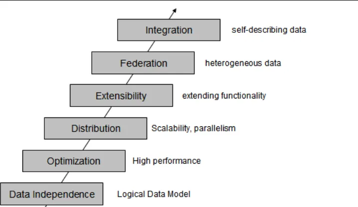
Figure 1.1 Evolution of database management systems
The above figure describes the evolution of database management systems with the relational model that provide for data independence. IBM's System R was the first system to implement Codd's ideas. System R was the basis for SQL/DS, which later became DB2. It also has the merit to introduce SQL, a relational database language used as a standard today, and to open the door for commercial database management systems.
Today, relational database management systems are the most used DBMS's and are developed by several software companies. IBM is one of the leaders in the market with DB2 database server. Other relational DBMS's include Oracle, Microsoft SQL Server, INGRES, PostgreSQL, MySQL, and dBASE.
As relational databases became increasingly popular, the need to deliver high performance queries has arisen. DB2's optimizer is one of the most sophisticated components of the product. From a user's perspective, you treat DB2's optimizer as a black box, and pass any SQL query to it. The DB2's optimizer will then calculate the fastest way to retrieve your data by taking into account many factors such as the speed of your CPU and disks, the amount of data available, the location of the data, the type of data, the existence of indexes, and so on. DB2's optimizer is cost-based.
As increased amounts of data were collected and stored in databases, DBMS's scaled. In DB2 for Linux, UNIX and Windows, for example, a feature called Database Partitioning Feature (DPF) allows a database to be spread across many machines using a shared-nothing architecture. Each machine added brings its own CPUs and disks; therefore, it is easier to scale almost linearly. A query in this environment is parallelized so that each machine retrieves portions of the overall result.
to develop their own code that can extend SQL. For example, in DB2 you can create user-defined functions, and stored procedures, which allow you to extend the SQL language with your own logic.
Then DBMS's started tackling the problem of handling different types of data and from different sources. At one point, the DB2 data server was renamed to include the term "Universal" as in "DB2 universal database" (DB2 UDB). Though this term was later dropped for simplicity reasons, it did highlight the ability that DB2 data servers can store all kinds of information including video, audio, binary data, and so on. Moreover, through the concept of federation a query could be used in DB2 to access data from other IBM products, and even non-IBM products.
Lastly, in the figure the next evolutionary step highlights integration. Today many businesses need to exchange information, and the eXtensible Markup Language (XML) is the underlying technology that is used for this purpose. XML is an extensible, self-describing language. Its usage has been growing exponentially because of Web 2.0, and service-oriented architecture (SOA). IBM recognized early the importance of XML; therefore, it developed a technology called pureXML® that is available with DB2 database servers. Through this technology, XML documents can now be stored in a DB2 database in hierarchical format (which is the format of XML). In addition, the DB2 engine was extended to natively handle XQuery, which is the language used to navigate XML documents. With pureXML, DB2 offers the best performance to handle XML, and at the same time provides the security, robustness and scalability it has delivered for relational data through the years.
The current "hot" topic at the time of writing is Cloud Computing. DB2 is well positioned to work on the Cloud. In fact, there are already DB2 images available on the Amazon EC2 cloud, and on the IBM Smart Business Development and Test on the IBM Cloud (also known as IBM Development and Test Cloud). DB2's Database Partitioning Feature previously described fits perfectly in the cloud where you can request standard nodes or servers on demand, and add them to your cluster. Data rebalancing is automatically performed by DB2 on the go. This can be very useful during the time when more power needs to be given to the database server to handle end-of-the-month or end-of-the-year transactions.
1.3 Introduction to information models and data models
An information model is an abstract, formal representation of entities that includes their properties, relationships and the operations that can be performed on them. The entities being modeled may be from the real world, such as devices on a network, or they may themselves be abstract, such as the entities used in a billing system.
example, using unified modeling language - UML), entity relationship models, or XML schemas.
Modeling is important as it considers the flexibility required for possible future changes without significantly affecting usage. Modeling allows for compatibility with its predecessor models and has provisions for future extensions.
Information Models and Data Models are different because they serve different purposes. The main purpose of an Information Model is to model managed objects at a conceptual level, independent of any specific implementations or protocols used to transport the data. The degree of detail of the abstractions defined in the Information Model depends on the modeling needs of its designers. In order to make the overall design as clear as possible, an Information Model should hide all protocol and implementation details. Another important characteristic of an Information Model is that it defines relationships between managed objects.
Data Models, on the other hand, are defined at a more concrete level and include many details. They are intended for software developers and include protocol-specific constructs. A data model is the blueprint of any database system. Figure 1.1 illustrates the relationship between an Information Model and a Data Model.
Figure 1.1 - Relationship between an Information Model and a Data Model
Since conceptual models can be implemented in different ways, multiple Data Models can be derived from a single Information Model.
1.4 Types of information models
Information model proposals can be split into nine historical epochs: Network (CODASYL): 1970’s
Hierarchical (IMS): late 1960’s and 1970’s Relational: 1970’s and early 1980’s Entity-Relationship: 1970’s
Extended Relational: 1980’s Information Model
Data Model Data Model Data Model
Conceptual/abstract model
for designers and operators
Concrete/detailed model
Semantic: late 1970’s and 1980’s
Object-oriented: late 1980’s and early 1990’s Object-relational: late 1980’s and early 1990’s Semi-structured (XML): late 1990’s to the present The next sections discuss some of these models in more detail.
1.4.1 Network model
In 1969, CODASYL (Committee on Data Systems Languages) released its first specification about the network data model. This followed in 1971 and 1973 with specifications for a record-at-a-time data manipulation language. An example of the CODASYL network data model is illustrated in Figure 1.2.
Figure 1.2 - A network model
The figure shows the record types represented by rectangles. These record types can also use keys to identify a record. A collection of record types and keys form a CODASYL network or CODASYL database. Note that a child can have more than one parent, and that each record type can point to each other with next, prior and direct pointers.
1.4.2 Hierarchical model
Figure 1.3 - A Hierarchical model
In a hierarchical model, a collection of named fields with their associated data types is called a record type. Each instance of a record type is forced to obey the data description indicated in the definition of the record type. Some fields in the record type are keys. The first hierarchical database management system was IMS (Information Management System) released by IBM in 1968. It was originally built as the database for the Apollo space program to land the first humans on the moon. IMS is a very robust database that is still in use today at many companies worldwide.
1.4.3 Relational model
The relational data model is simple and elegant. It has a solid mathematic foundation based on sets theory and predicate calculus and is the most used data model for databases today.
One of the drivers for Codd's research was the fact that IMS programmers were spending large amounts of time doing maintenance on IMS applications when logical or physical changes occurred; therefore, his goal was to deliver a model that provided better data independence. His proposal was threefold:
Store the data in a simple data structure (tables)
Access it through a high level set-at-a-time Data Manipulation Language (DML) Be independent from physical storage
Figure 1.4 - An E-R diagram showing a sample relational model
1.4.4 Entity-Relationship model
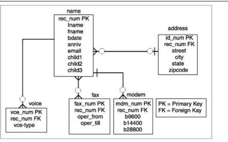
Figure 1.5 - An E-R Diagram for a telephone directory data model
In the figure, entities are represented by rectangles and they are name, address, voice,
fax, and modem. Attributes are listed inside each entity. For example, the voice entity has the vce_num, rec_num, and vce-type as attributes. PK represents a primary key, and FK a foreign key. The concept of keys is discussed in more detail later in this book.
Rather than being used as a model on its own, the E-R model has found success as a tool to design relational databases. Chen’s papers contained a methodology for constructing an initial E-R diagram. In addition, it was a simple process to convert an E-R diagram into a collection of tables in third normal form. For more information on the Third normal form and the normalization theory see the later parts of the book.
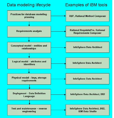
Today, the ability to create E-R diagrams are incorporated into data modeling tools such as IBM InfoSphere™ Data Architect. To learn more about this tool refer to the eBook Getting started with InfoSphere Data Architect, which is part of the DB2 on Campus book series.
1.4.5 Object-relational model
The Object-Relational (OR) model is very similar to the relational model; however, it treats every entity as an object (instance of a class), and a relationship as an inheritance. Some features and benefits of an Object-Relational model are:
Support for complex, user defined types Object inheritance
Extensible objects
1.4.6 Other data models
The last decade has seen a substantial amount of work on semi-structured, semantic and object oriented data models.
XML is ideal to store semi-structured data. XML-based models have gained a lot of popularity in the industry thanks to Web 2.0 and service-oriented architecture (SOA). Object oriented data models are popular in universities, but have not been widely accepted in the industry; however, object-relational mapping (ORM) tools are available which allow a seamless integration of object-oriented programs with relational databases.
1.5 Typical roles and career path for database professionals
Like any other work profile, the database domain has several of roles and career paths associated with it. The following is a description of some of these roles.
1.5.1 Data Architect
A data architect is responsible for designing an architecture that supports the organization's existing and future needs for data management. The architecture should cover databases, data integration and the means to get to the data. Usually the data architect achieves his goals by setting enterprise data standards. A Data Architect is also referred to as a Data Modeler. This is in spite of the fact that the role involves much more than just creating data models.
Some fundamental skills of a Data Architect are: Logical Data modeling
Physical Data modeling
Development of a data strategy and associated policies
Selection of capabilities and systems to meet business information needs
1.5.2 Database Architect
This role is similar to a Data Architect, though constraints more towards a database solution. A database architect is responsible for the following activities:
Gather and document requirements from business users and management and address them in a solution architecture.
Share the architecture with business users and management.
Create and enforce database and application development standards and processes.
Study new products, versions compatibility, and deployment feasibility and give recommendations to development teams and management.
Understand hardware, operating system, database system, multi-tier component architecture and interaction between these components.
Prepare high-level documents in-line with requirements. Review detailed designs and implementation details.
It is critical for a database architect to keep pace with the various tools, database products, hardware platforms and operating systems from different vendors as they evolve and improve.
1.5.3 Database Administrator (DBA)
A database administrator (DBA) is responsible for the maintenance, performance, integrity and security of a database. Additional role requirements are likely to include planning, development and troubleshooting.
The work of a database administrator (DBA) varies according to the nature of the employing organization and the level of responsibility associated with the post. The work may be pure maintenance or it may also involve specializing in database development. Typical responsibilities include some or all of the following:
Establishing the needs of users and monitoring user access and security;
Monitoring performance and managing parameters to provide fast query responses to front-end users;
Mapping out the conceptual design for a planned database in outline;
Take into account both, back-end organization of data and front-end accessibility for end users;
Refining the logical design so that it can be translated into a specific data model; Further refining the physical design to meet system storage requirements;
Installing and testing new versions of the database management system (DBMS); Maintaining data standards, including adherence to the Data Protection Act;
Writing database documentation, including data standards, procedures and definitions for the data dictionary (metadata);
Controlling access permissions and privileges;
Developing, managing and testing backup and recovery plans;
Ensuring that storage, archiving, backup and recovery procedures are functioning correctly;
Working closely with IT project managers, database programmers and Web developers;
Communicating regularly with technical, applications and operational staff to ensure database integrity and security;
Commissioning and installing new applications.
Because of the increasing levels of hacking and the sensitive nature of data stored, security and recoverability or disaster recovery have become increasingly important aspects.
1.5.4 Application Developer
A database application developer is a person in charge of developing applications that access databases. An application developer requires knowledge of the following:
Integrated database application development environments (IDEs). Database plug-ins for IDEs.
SQL development tools
Database performance monitoring and debugging
Application server environments, application deployment, application performance monitoring and debugging
An example of an IDE is IBM Data Studio, a free Eclipse-based environment which allows developers to work with DB2 objects such as tables, views, indexes, stored procedures, user-defined functions and Web services. It also provides facilities for debugging, development of SQL and XQuery, and integration with different application servers such as WebSphere® Application Server.
DB2 also includes add-ins that extend Microsoft® Visual Studio development environment with a comprehensive set of tools for developing DB2 objects (tables, views, stored procedures, user-defined functions etc.). This way, .NET developers do not need to switch back and forth between Microsoft Visual Studio and DB2 tools.
The roles and responsibilities discussed so far are very broad classifications. Different organizations have their own definition of roles within their organization’s context. These roles are listed to provide a big picture on various dimensions around database administration, application development and usage.
1.6 Summary
1.7 Exercises
1. Learn more about databases by practicing with DB2 Express-C, the free version of DB2 database server. You can download this product at 2. Learn more about IDEs by practicing with the free IBM Data Studio. You can
download this product also at
1.8 Review questions
1. What is a database?
2. What is a database management system?
3. What is the difference between an Information model, and a Data model? 4. What is the main advantage of the relational model versus other models? 5. List two common tasks a DBA has to perform
6. Which of the following is not an information model: 1. A. pureXML model
2. B. Relational model 3. C. Hierarchical model 4. D. Network model 5. E. None of the above
7. In the evolution of database management systems, what does optimization refer to? 6. A. High availability
7. B. Security 8. C. Performance 9. D. Scalability
10. E. None of the above
8. Which of the following is not listed in the evolution of database management systems: 11. A. Distribution
12. B. Data Independence 13. C. Integration
14. D. Federation 15. E. None of the above
17. B. Extensibility 18. C. Optimization 19. D. Integration
20. E. None of the above
10. What is one key differentiator of DB2 on the Cloud? 21. A. It has a spatial extender
22. B. Its Database Partitioning Feature 23. C. Its pureXML technology
2
Chapter 2 – The relational data model
In this chapter, we discuss the basics of the relational data model. We introduce concepts like attributes, tuples, relations, domains, schemas and keys. We also describe the different types of relational model constraints and some information about relational algebra and calculus. This chapter is closely related to Chapter 3, The conceptual data model, where you will learn how to translate a conceptual data model into a relational database schema, and to Chapter 4, Relational database design, which presents important issues for designing a relational database. This chapter is also important for a better understanding of the SQL language.
In this chapter, you will learn about:
The big picture of the relational data model
The definitions of attributes, tuples, relations, domains, schemas and keys The relational model constraints
Relational algebra operations Relational calculus
2.1 Relational data model: The big picture
Information models try to put the real-world information complexity in a framework that can be easily understood. Data models must capture data structure and characteristics, the relationships between data, the data validation rules and constraints and all transformations the data must support. You can think of it as a communication tool between designers, programmers and end-users of a database. There are several types of data models on the market today and each of it has its own features. However, in this chapter we focus on the relational data model, which is the prevalent one in today's database market.
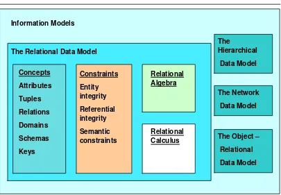
Figure 2.1 - Relational data model in context of information models: The big picture
Figure 2.1 shows the main aspects of the relational data model:
Specific relational data model concepts like attributes, tuples, domains, relations, domains, schemas, keys
The relational data model constraints like entity integrity, referential integrity, and semantic constraints which are used to enforce rules on a relational database
Relational algebra operations like union, intersection, difference, Cartesian product, selection, projection, join and division which are used to manipulate relations in a relational data model
Relational calculus which is an alternative to the relational algebra as a candidate for the manipulative part of the model
2.2 Basic concepts
The relational data model uses formal terms to define its concepts. In the following chapters, we use formal relational terminology like: attribute, domain, tuple, relation, schema, candidate key, primary key and foreign key. Let’s define each of these terms.
2.2.1 Attributes
An attribute is a characteristic of data. A real-world data feature, modeled in the database, will be represented by an attribute. An attribute has to have a name, so you can refer to
that feature, and the name has to be as relevant as possible for that feature. For example, for a person the attributes can be: Name, Sex, DateOfBirth. Informal terms used to define an attribute are: column in a table or field in a data file.
In Figure 2.2, you can see the attributes of a car: Type, Producer, Model,
FabricationYear, Color, Fuel. Other elements in the figure as discussed in the upcoming sections.
Figure 2.2 - CARS Relation – Header with attributes and body with tuples
2.2.2 Domains
A domain is a set of atomic values that are all of the same type. A value is the smallest unit of data in the relational model. For example, BMW, Mercedes, Audi, and VW are values for the attribute Producer. Those values are considered to be atomic, that is they are non-decomposable as far as the model is concerned. The domain for the Producer is the set of all possible car producer names. An attribute always has a domain associated with it. This domain gives the possible values for that attribute. Two or more attributes can be defined on the same domain.
A domain has a name, so we can make references to it, and a dimension. The dimension is given by the number of values that domain has. For example, Fuel attribute domain has only two values (GAS, DIESEL). A domain can be seen as a pool of values, from which the actual values appearing in attributes are drawn. Note that at any given time, there will be values included in a domain that do not currently appear in any of the attributes that correspond to that domain.
different domains, comparisons operations involving those two attributes do not make sense.
Domains are primarily conceptual in nature. In most cases, they are not explicitly stored in the database. The domains should be specified as a part of the database definition and then each attribute definition should include a reference to the corresponding domain, so that the system is aware of those attributes that are comparable to each other.
A given attribute may have the same name as the corresponding domain, but this situation should be avoided because it can generate confusion. However, it is possible to include the domain name as the trailing portion of the attribute name for the purpose of including more information in that attribute name.
2.2.3 Tuples
A tuple is an ordered set of values that describe data characteristics at one moment in time. In Figure 2.2 above, you can see an example of a tuple. Another formal term used to define a tuple is n-tuple. Informal terms used for tuples are: row in a table or record in a data file.
2.2.4 Relations
A relation is the core of the relational data. According to introduction to database systems [2.1] a relation on domains D1, D2, …, Dn (not necessarily distinct) consists of a heading and a body.
The heading consists of a fixed set of attributes A1, A2, …, An, such that each attribute
Ai corresponds to exactly one of the underlying domains Di (i=1, 2, …, n).
The body consists of a time-varying set of tuples, where each tuple in turn consists of a set of attribute-value pairs (Ai:vi) (i=1, 2, …, n), one such pair for each attribute Ai
in the heading. For any given attribute-value pair (Ai:vi), vi is a value from the unique domain Di that is associated with the attribute Ai.
In Figure 2.2, you can see the CARS relation. The relation heading consists of a fixed set of 6 attributes: Type, Producer, Model, FabricationYear, Color, Fuel. Each attribute has a corresponding domain. The relation body consists of a set of tuples (5 tuples are shown in the figure, but this set varies with time) and each tuple consists of a set of 6 attribute-value pairs, one such pair for each of the 6 attributes in the heading.
A relation degree is equivalent with the number of attributes of that relation. The relation from Figure 2.2 has a degree of 6. A relation of degree one is called unary, a relation of degree two binary, a relation of degree three ternary, and so on. A relation of degree n is called nary.
As you see in the relation, the body consists of a time-varying set of tuples. At one moment in time, the relation cardinality may be m, while another moment in time the same relation may have the cardinality n. The state in which a relation exists at one moment in time is called a relation instance. Therefore, during a relation’s lifetime there may be many relation instances.
Relations possess certain important properties. These properties are all of them consequences of the relation definition given above. The four properties are as follows:
There are no duplicate tuples in a relation Tuples are unordered (top to bottom) Attributes are unordered (left to right) All attribute values are atomic
Informal terms used for relations are table or data file.
2.2.5 Schemas
A database schema is a formal description of all the database relations and all the relationships existing between them. In Chapter 3, Conceptual data modeling, and Chapter 4, Relational database design, you will learn more about a relational database schema.
2.2.6 Keys
The relational data model uses keys to define identifiers for a relation’s tuples. The keys are used to enforce rules and/or constraints on database data. Those constraints are essential for maintaining data consistency and correctness. Relational DBMS permits definition of such keys, and starting with this point the relational database management system is responsible to verify and maintain the correctness and consistency of database data. Let’s define each type of key.
2.2.6.1 Candidate keys
A candidate key is a unique identifier for the tuples of a relation. By definition, every relation has at least one candidate key (the first property of a relation). In practice, most relations have multiple candidate keys.
C. J. Date in [2.2] gives the following definition for a candidate key:
Let R be a relation with attributes A1, A2, …, An. The set of K=(Ai, Aj, …, Ak) of R
is said to be a candidate key of R if and only if it satisfies the following two time-independent properties:
Uniqueness
At any given time, no two distinct tuples of R have the same value for Ai, the same value for Aj, …, and the same value for Ak.
None of Ai, Aj, …, Ak can be discarded from K without destroying the uniqueness property.
Every relation has at least one candidate key, because at least the combination of all of its attributes has the uniqueness property (the first property of a relation), but usually exist at least one other candidate key made of fewer attributes of the relation. For example, the
CARS relation shown earlier in Figure 2.2 has only one candidate key K=(Type, Producer, Model, FabricationYear, Color, Fuel) considering that we can have multiple cars with the same characteristics in the relation. Nevertheless, if we create another relation CARS as in Figure 2.3 by adding other two attributes like SerialNumber
(engine serial number) and IdentificationNumber (car identification number) we will have 3 candidate keys for that relation.
The new CARS Relation
Figure 2.3 – The new CARS Relation and its candidate keys
A candidate key is sometimes called a unique key. A unique key can be specified at the Data Definition Language (DDL) level using the UNIQUE parameter beside the attribute name. If a relation has more than one candidate key, the one that is chosen to represent the relation is called the primary key, and the remaining candidate keys are called alternate keys.
Note:
To correctly define candidate keys you have to take into consideration all relation instances to understand the attributes meaning so you can be able to determine if duplicates are possible during the relation lifetime.
A primary key is a unique identifier of the relation tuples. As mentioned already, it is a candidate key that is chosen to represent the relation in the database and to provide a way to uniquely identify each tuple of the relation. A database relation always has a primary key.
Relational DBMS allow a primary key to be specified the moment you create the relation (table). The DDL sublanguage usually has a PRIMARY KEY construct for that. For example, for the CARS relation from Figure 2.3 the primary key will be the candidate key
IdentificationNumber. This attribute values must be “UNIQUE” and “NOT NULL” for all tuples from all relation instances.
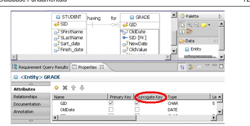
There are situations when real-world characteristic of data, modeled by that relation, do not have unique values. For example, the first CARS relation from Figure 2.2 suffers from this inconvenience. In this case, the primary key must be the combination of all relation attributes. Such a primary key is not a convenient one for practical matters as it would require too much physical space for storage, and maintaining relationships between database relations would be more difficult. In those cases, the solution adopted is to introduce another attribute, like an ID, with no meaning to real-world data, which will have unique values and will be used as a primary key. This attribute is usually called a surrogate key. Sometimes, in database literature, you will also find it referenced as artificial key.
Surrogate keys usually have unique numerical values. Those values grow or decrease automatically with an increment (usually by 1).
2.2.6.3 Foreign keys
A foreign key is an attribute (or attribute combination) in one relation R2 whose values are required to match those of the primary key of some relation R1 (R1 and R2 not necessarily distinct). Note that a foreign key and the corresponding primary key should be defined on the same underlying domain.
OWNERS Relation
Figure 2.4 – The OWNERS relation and its primary and foreign keys
The IdentificationNumber foreign key from the OWNERS relation refers to the
IdentificationNumberprimary key from CARS relation. In this manner, we are able to know which car belongs to each person.
Foreign-to-primary-key matches represent references from one relation to another. They are the “glue” that holds the database together. Another way of saying this is that foreign-to-primary-key matches represent certain relationships between tuples. Note carefully, however, that not all such relationships are represented by foreign-to-primary-key matches.
The DDL sublanguage usually has a FOREIGN KEY construct for defining the foreign keys. For each foreign key the corresponding primary key and its relation is also specified.
2.3 Relational data model constraints
In a relational data model, data integrity can be achieved using integrity rules or constraints. Those rules are general, specified at the database schema level, and they must be respected by each schema instance. If we want to have a correct relational database definition, we have to declare such constraints [2.2]. If a user attempts to execute an operation that would violate the constraint then the system must then either reject the operation or in more complicated situations, perform some compensating action on some other part of the database.
This would ensure that the overall result is still in a correct state. Now, let’s see what the relational data model constraints are.
2.3.1 Entity integrity constraint
A null represents property inapplicable or information unknown. Null is simply a marker indicating the absence of a value, an undefined value. That value that is understood by convention not to stand for any real value in the applicable domain of that attribute. For example, a null for the car color attribute of a car means that for the moment we do not know the color of that car.
The justification for the entity integrity constraint is:
Database relations correspond to entities from the real-world and by definition entities in the real-world are distinguishable, they have a unique identification of some kind
Primary keys perform the unique identification function in the relational model Therefore, a null primary key value would be a contradiction in terms because it
would be saying that there is some entity that has no identity that does not exist.
2.3.2 Referential integrity constraint
The referential integrity constraint says that if a relation R2 includes a foreign key FK
matching the primary keyPK of other relation R1, then every value of FK in R2 must either be equal to the value of PK in some tuple of R1 or be wholly null (each attribute value participating in that FK value must be null). R1 and R2 are not necessarily distinct.
The justification for referential integrity constraint is:
If some tuple t2 from relation R2 references some tuple t1 from relation R1, then tuple t1 must exist, otherwise it does not make sense
Therefore, a given foreign key value must have a matching primary key value somewhere in the referenced relation if that foreign key value is different from null Sometimes, for practical reasons, it is necessary to permit the foreign key to accept
null values
For example, in our OWNERS relation the foreign key is IdentificationNumber. This attribute value must have matching values in the CARS relation, because a person must own an existing car to become an owner. If the foreign key has a null value, that means that the person does not yet have a car, but he could buy an existing one.
For each foreign key in the database, the database designer has to answer three important questions:
Can the foreign key accept null values?
For example, does it make sense to have an owner for which the car he owns is not known? Note that the answer to this question depends, not on the whim of the database designer, but on the policies in effect in the portion of the real-world that is to be represented in the database.
For example, an attempt to delete a car which is owned by a person? In general, there are three possibilities:
1. CASCADE – the delete operation “cascades” to delete those matching tuples also (the tuples from the foreign key relation). In our case, if the car is deleted the owner is deleted, too.
2. RESTRICT - the delete operation is “restricted” to the case where there are no such matching tuples (it is rejected otherwise). In our case, the car can be deleted only if it is not owned by a person.
3. NULLIFIES – the foreign key is set to null in all such matching cases and the tuple containing the primary key value is then deleted (of course, this case could not apply if the foreign key cannot accept null values). In our case, the car can be deleted after the IdentificationNumber attribute value of its former owner is set to null.
What should happen on an attempt to update the primary key value of a foreign key reference?
In general, there are also three possibilities:
1. CASCADE – the update operation “cascades” updates the foreign key value of those matching tuples (including the tuples from the foreign key relation). In our case, if the car identification number is updated the car owner identification number is updated, too.
2. RESTRICT - the update operation is “restricted” to the case where there are no such matching tuples (it is rejected otherwise). In our case, the car identification number can be updated only if it is not owned by a person.
3. NULLIFIES – the foreign key is set to null in all such matching cases and the tuple containing the primary key value is then updated (of course, this case could not apply if the foreign key cannot accept null values). In our case, the car identification number can be updated after the IdentificationNumber attribute value of its former owner is set to null.
2.3.3 Semantic integrity constraints
A semantic integrity constraint refers to the correctness of the meaning of the data. For example, the street number attribute value from the OWNERS relation must be positive, because the real-world street numbers are positive.
A semantic integrity constraint can be regarded as a predicate that all correct states of relations instances from the database are required to satisfy.
should include, not only the ability to specify arbitrary predicates, but also facilities for specifying such compensating actions when appropriate.
Semantic integrity constraints must be specified typically by a database administrator and must be maintained in the system catalog or dictionary. The DBMS monitors user interactions to ensure that the constraints are in fact respected. Relational DBMS permits several types of semantic integrity constraints such as domain constraint, null constraint, unique constraint, and check constraint.
2.3.3.1 Domain constraint
A domain constraint implies that a particular attribute of a relation is defined on a particular domain. A domain constraint simply states that values of the attribute in question are required to belong to the set on values constituting the underlying domain.
For example, the Street attribute domain of OWNERS relation is CHAR(20), because streets have names in general and Number attribute domain is NUMERIC, because street numbers are numeric values.
There are some particular forms of domain constraints, namely format constraints and range constraints. A format constraint might specify something like a data value pattern. For example, the IdentificationNumber attribute values must be of this type
XX99XXX, where X represents an alphabet letter and 9 represents a digit. A range constraint requires that values of the attribute lie within the range values. For example, the
FabricationYear attribute values might range between 1950 and 2010.
2.3.3.2 Null constraint
A null constraint specifies that attribute values cannot be null. On every tuple, from every relation instance, that attribute must have a value which exists in the underlying attribute domain. For example, FirstName and LastName attributes values cannot be null, this means that a car owner must have a name.
A null constraint is usually specified with the NOT NULL construct. The attribute name is followed by the words NOT NULL for that. Along with NOT NULL, the additional keyword “WITH DEFAULT” can optionally be specified so that the system generates a default value for the attribute in case it is null at the source while inserting. WITH DEFAULT is only applicable for numeric (integer, decimal, float etc.) and date (date, time, timestamp) data types. For other types, default value should be provided explicitly in the DDL.
2.3.3.3 Unique constraint
A unique constraint specifies that attribute values must be different. It is not possible to have two tuples in a relation with the same values for that attribute. For example, in the
Note:
NULL is not part of any domain; therefore, a basic SQL comparison returns “unknown” when any one of the values involved in the processing is NULL. Therefore to handle NULL correctly, SQL provides two special predicates, “IS NULL” and “IS NOT NULL” to check if the data is null or not. Below is a brief summary table that indicates how NULL ("Unknown") is handled by SQL. Different database vendors/platforms may have a different ways of handling NULL.
A B A OR B A AND B A = B A NOT A
True True True True True True False
True False True False False False True
True Unknown True Unknown Unknown Unknown Unknown
False True True False False
False False False False False
False Unknown Unknown False False
Unknown True True Unknown Unknown
Unknown False Unknown False False
Unknown Unknown Unknown Unknown Unknown
2.3.3.4 Check constraint
A check constraint specifies a condition (a predicate) on a relation data, which is always checked when data is manipulated. The predicate states what to check, and optionally what to do if the check fails (violation response). If this violation response is omitted, the operation is rejected with a suitable return code. When the constraint is executed, the system checks to see whether the current state of the database satisfies the specified constraint. If it does not, the constraint is rejected, otherwise it is accepted and enforced from that time on.
For example, an employee's salary can’t be greater than his manager's salary or a department manager can’t have more that 20 people reporting to him. For our previous relations, for example, the fabrication year of a car can’t be greater than the current year or a car can be owned by a single person.
This type of constraint can sometimes be specified in the database using a CHECK