DETERMINATION OF EXTERIOR ORIENTATION PARAMETERS THROUGH
DIRECT GEO-REFERENCING IN A REAL-TIME AERIAL MONITORING SYSTEM
Hojun Kim, Jihun Lee, Kyoungah Choi, Impyeoung Lee*
Dept. of Geoinformatics, The University of Seoul, Seoul, Republic of Korea - (zzimss, fantest, shale, iplee)@uos.ac.kr
Commission V, ICWG I/V
KEY WORDS: Real-time Aerial Monitoring, Multi-sensor System, Direct Geo-referencing, Disaster Response, Unmanned Aerial Vehicle (UAV)
ABSTRACT:
Rapid responses for emergency situations such as natural disasters or accidents often require geo-spatial information describing the on-going status of the affected area. Such geo-spatial information can be promptly acquired by a manned or unmanned aerial vehicle based multi-sensor system that can monitor the emergent situations in near real-time from the air using several kinds of sensors. Thus, we are in progress of developing such a real-time aerial monitoring system (RAMS) consisting of both aerial and ground segments. The aerial segment acquires the sensory data about the target areas by a low-altitude helicopter system equipped with sensors such as a digital camera and a GPS/IMU system and transmits them to the ground segment through a RF link in real-time. The ground segment, which is a deployable ground station installed on a truck, receives the sensory data and rapidly processes them to generate ortho-images, DEMs, etc. In order to generate geo-spatial information, in this system, exterior orientation parameters (EOP) of the acquired images are obtained through direct geo-referencing because it is difficult to acquire coordinates of ground points in disaster area. The main process, since the data acquisition stage until the measurement of EOP, is discussed as follows. First, at the time of data acquisition, image acquisition time synchronized by GPS time is recorded as part of image file name. Second, the acquired data are then transmitted to the ground segment in real-time. Third, by processing software for ground segment, positions/attitudes of acquired images are calculated through a linear interpolation using the GPS time of the received position/attitude data and images. Finally, the EOPs of images are obtained from position/attitude data by deriving the relationships between a camera coordinate system and a GPS/IMU coordinate system. In this study, we evaluated the accuracy of the EOP decided by direct geo-referencing in our system. To perform this, we used the precisely calculated EOP through the digital photogrammetry workstation (DPW) as reference data. The results of the evaluation indicate that the accuracy of the EOP acquired by our system is reasonable in comparison with the performance of GPS/IMU system. Also our system can acquire precise multi-sensory data to generate the geo-spatial information in emergency situations. In the near future, we plan to complete the development of the rapid generation system of the ground segment. Our system is expected to be able to acquire the ortho-image and DEM on the damaged area in near real-time. Its performance along with the accuracy of the generated geo-spatial information will also be evaluated and reported in the future work.
* Corresponding author.
1. INTRODUCTION
As emergency situations such as natural disasters or accidents being increased, the need for effective disaster management system for rapid responses also has been increasing. In such a system, it is important to identify the exact situation of the damaged area to minimize a loss of lives and properties. Furthermore, large-scale natural disasters such as a tsunami in Japan are required to rapidly acquire the geo-spatial information describing the on-going status of the damaged area because the impact of damage is huge. Traditionally, many previous methods for disaster damage assessment are based on satellites and specially-suited manned aircraft. However, for many reasons, these technologies have limitations in fulfilling the flexible, quick-response needs of effective disaster management (Bowman 2008). In recent years, in order to overcome the limitations, the aerial monitoring systems based on low-altitude manned or unmanned aerial vehicles (UAV) have been developed.
Haarbrink et al. (2006) developed a fully operational helicopter UAV with automatic triggering capability for photogrammetric
image acquisition and rapid response operations. Zhou et al. (2005) developed a UAV based video system for generating high-resolution planimetric mapping for the purpose of forest fire surveillance. Ahmed et al. (2008) developed a UAV based monitoring system to enhance the search and rescue operations in a disaster area. In addition to disaster response, various studies have been performed to acquire 3D geo-spatial information effectively using a UAV. Nagai et al. (2004) used an unmanned helicopter loaded the measurement tools to construct digital surface model. Eisenbeiss (2004) recorded
spatial information of Peru’s cultural heritage by using an UAV system.
From these previous studies, it has been proven that aerial monitoring systems using the low-altitude UAV can acquire sensory data of target areas quickly and economically. However, most of the systems developed from previous studies are not fast enough to deliver rapid responses for emergency situations because these systems do not transmit or process data in real-time. To compensate for this, we attempted to develop a low-altitude UAV based real-time aerial monitoring system (RAMS), International Archives of the Photogrammetry, Remote Sensing and Spatial Information Sciences, Volume XXXIX-B1, 2012
which can be performed data acquisition, transmission and processing in near real-time (Choi et al. 2011).
The purpose of our system is to provide accurate geo-spatial information of damaged areas rapidly in emergency situations by acquiring multi-sensory data and generating geo-spatial information such as ortho-image and DEM (Digital Elevation Model). Now, we are in progress of developing this system and manage a demonstration in test area. In this study, we introduce our developed system and verify the acquired image's EOP through direct geo-referencing of multi-sensory data. Direct geo-referencing, which is a fundamental data processing method to generate geo-spatial information in real-time is necessary for emergency mapping solution. Therefore, we try to measure the possibility of this system for emergency situation by verifying the accuracy of direct geo-referencing.
2. REAL-TIME AERIAL MONITORING SYSTEM
The real-time aerial monitoring system based on a unmanned helicopter acquires multi-sensory data of target areas and then generates the geo-spatial information in real-time. This system is composed of aerial and ground segment (Figure 1). The aerial segment acquires the multi-sensory data and transmits it to the ground segment. The ground segment is connected with the aerial segment by wireless via an RF link system and generates geo-spatial information rapidly through receiving/archiving /processing of the acquired data.
Figure 1. Real-time Aerial Monitoring System 2.1 Aerial Segment
The aerial segment is composed of an UAV, a sensor part and a supporting module part. This segment acquires sensory data and transmits it to the ground segment. We use a low-altitude unmanned helicopter which can autonomously fly. Sensors and supporting modules are mounted on an independent frame and then built into the platform. Shark-120 model developed by Oneseen Skytech is the UAV used in this study and its appearance and specification are in Figure 2 and Table 1.
Figure 2. Unmanned Helicopter (Shark-120)
Main rotor 4 rotors, diameter 3.12m
Motor 294cc 35HP, 6,500rpm
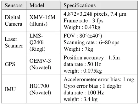
The sensor part is composed of a digital camera, a laser scanner, a GPS and an INS. The existing sensors for traditional aerial survey are high-priced because of its accurate data acquisition, but in this case we adopt a middle-priced and light-weight sensor for UAV weight allowance. Main features of sensors are in Table 2, sensor and supporting parts are mounted on frame in Figure 3. The supporting module part is composed of an OBC (On-Board Computer), an RF link system and a power supply module. The OBC developed for this system by ourselves controls whole sensors, stores data and performs time synchronization of sensor data. The RF link system connects an OBC with the ground segment by wireless, and the power supply module provides power to whole sensors.
Sensors Model Specifications
Figure 3. Sensors & Supporting Modules 2.2 Ground Segment
The ground segment is composed of a mobile ground station, receiving and processing parts. This segment receives and archives the data from the aerial segment and then generates geo-spatial information rapidly. The ground station is a remodelled 2.5-ton truck, which includes receiving and processing systems (Figure 4). The receiving part stores the sensory data from the aerial system, which is composed of an antenna tracking system, and a sensor control and data receiving system. The antenna tracking system controls the direction of antenna to maintain wireless communication between the aerial and ground segments. The sensor control and data receiving system, which is connected with aerial system via a wireless link controls the sensors and receives and archives the acquired data. The processing part is composed of a data processing system, a geo-spatial data generation system, and a visualization system. The data processing system determines the EOP (Exterior Orientation Parameters) of the acquired images by a direct geo-referencing scheme and generates geo-referenced LiDAR data. The geo-spatial data generation system generates DEMs and ortho-images from the geo-referenced images and LiDAR data. The visualization system displays the generated geo-spatial information on a monitoring screen.
Figure 4. Ground Segment
3. DIRECT GEO-REFERENCING
The data processing system performs image geo-referencing using a direct geo-referencing method as an inevitable intermediate process toward the generation of geo-spatial
information. The direct geo-referencing method is essential for rapid mapping since it does not require the ground control points (GCP) which may require manual intervention. In our system, direct geo-referencing determines the exterior orientation parameters of the acquired images using the position and attitude data obtained from the GPS/INS mounted in UAV. For this process, the sensory data acquired by each sensor have to be precisely time-synchronized and the geometric relationship between each sensor coordinate systems must be accurately defined.
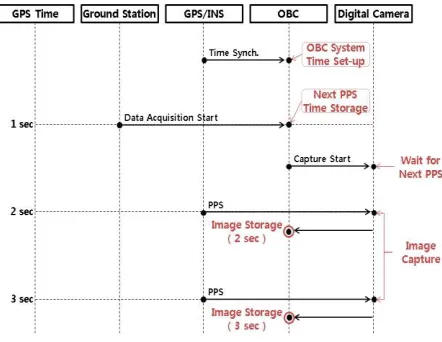
3.1 Time Synchronization
The time synchronization means that the acquisition time of each data acquired by multi-sensors mounted in the aerial segment should be recorded in the same time domain. The overall time synchronization scheme is shown in Figure 5. Since the GPS/INS system exports the position/attitude data tagged with the GPS time, we should measure the image acquisition time of the camera to the GPS time domain. We thus deliver pulse-per-second (PPS) signal triggered every second according to the GPS time to the camera and OBC via hardwired cables. The camera acquires an image whenever it receives the PPS signal, and the acquisition time is accurately recorded by the OBC. The OBC time is also adjusted to the GPS time using the PPS signal when the OBC is boot-up.
Figure 5. Time Synchronization of Image 3.2 Coordinate Systems & Geometric Models
For direct geo-referencing, we should accurately identify the geometric relationships between different sensor coordinate systems. First, we have to define the coordinate system for each sensor. A TM coordinate system is used for ground reference coordinates. The GPS/INS coordinate system is defined on the body frame, where its origin locates inside the IMU sensor. The position is provided with the WGS 84 coordinate system and the attitude is provided by comparing with the NED coordinate system. Images captured through digital camera are defined on the camera coordinate system, where its origin locates around the origin of the lens. The relationship between individual sensor coordinate systems is defined with a rotation matrix and a translation vector indicating the differences of the attitude and position, respectively. The rotation matrix ( ) and translation vector ( ) between the ground coordinate system and the GPS/INS coordinate system are determined by acquired position/attitude data. We then converted the acquired position/attitude data into the TM coordinate system, assuming International Archives of the Photogrammetry, Remote Sensing and Spatial Information Sciences, Volume XXXIX-B1, 2012
that the TM and NED coordinate systems are parallel. The rotation matrix ( ) between the GPS/INS and the digital camera is simply maintained by mounting the sensors in parallel. The translation vector ( ) is directly measured at initial mounting stage. To identify the accurate geometric relationship between each sensor, we should perform system calibration. However, the error associated with a medium grade GPS/INS is expected to exceed the calibration error between each sensor. It is acceptable to determine the geometric relationships by direct measurement. Figure 6 shows the geometrical model between individual sensor coordinate systems.
Figure 6. Geometry Model 3.3 Geo-referencing Equations
Direct geo-referencing of the sensor data is based on the entire geometric models. Image geo-referencing is performed through the position/attitude data of the GPS/INS, the rotation matrix and translation vector between the GPS/INS and the camera which are acquired at the same time. The exterior orientation of images means the position ( ) and attitude ( ) of the camera expressed in the ground coordinate system, which are computed by Eq. (1). The camera acquired a new image every second of the GPS time as triggered by the PPS signal. Therefore, we store the GPS time as the images’ file name and use it for the search of the GPS/INS data corresponding to the image acquisition time.
(1)
4. ACCURACY EVALUATION OF DIRECT GEO-REFERENCING
We dispatched the developed RAMS over a test area and acquired the geo-referenced sensory data. These data were then verified to assess the accuracy of direct geo-referencing. We created a reference data using the ortho-images and digital maps of the test area. The accuracy assessment is performed through comparative analysis between the reference data and the EOP of the images determined by direct geo-referencing.
4.1 Data Acquisition
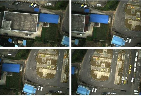
The test site is nearby Gangnae-myeon, Cheongwon-gun, Chungbuk in Korea which covers approximately 400*300 . The flight was performed at the height of about 100 m with the velocity of 30km/h. Our system acquires images at 1Hz and GPS/INS data at 20Hz. The system continuously transmits the data during their acquisition in the air. Also the EOPs of the images are generated through a geo-referencing system. Finally
we obtained about 250 images with their EOP. The acquired data are presented as Figure 7.
Figure 7. Acquired Images 4.2 Reference Data
To obtain referenced data, we selected feature points from ortho-images and digital map. Then, the feature points are used as GCP (Ground Control Points) when we estimated the EOPs of the images are the reference data. The estimation is performed by a DPW (Digital Photogrammetry Workstation), Socet Set 5.5.0. We carefully select two sets of 10 consecutive images covering enough number of GCPs. The estimated EOP of the centred three images among each set of 10 images are assumed to be accurate and hence used as the reference data. 4.3 Accuracy of Image Geo-referencing
We analyzed the accuracy of the image’s EOP determined by the direct geo-referencing method of our system using the EOP determined by the DPW using GCPs as the reference data. The comparative results showed that the RMSE are shown in Table 3. Considering that the accuracy of position/attitude provided by the GPS/INS is 1.5, 0.03 deg and the error tolerance of the ortho-images and the digital maps is 2 m, this result is reasonable. Our system can achieve the accuracy of 1~3 m, and hence our system are considered to acquire meaningful geo-spatial information rapidly in emergency area.
∆X ∆Y ∆Z ∆ω ∆φ ∆κ
Ave. 0.905 -0.967 -1.530 0.31661 -0.08466 0.36916
Std. 2.923 2.683 0.835 0.59491 1.25529 0.54239
RMS 3.087 2.885 1.873 0.68863 1.25871 0.67655
Table 3. EOP Errors
5. CONCLUSION
In this study, we introduce a real-time aerial data acquisition system which is developed for the purpose of providing rapid and accurate geo-spatial information in the emergency situation such as disasters or accidents. We checked the accuracy of the image geo-referencing performed by our system. This system consists of sensor, aerial and ground segment. The sensor segment includes UAV, digital camera, laser scanner and GPS/INS. The aerial segment is includes OBC, and RF system. International Archives of the Photogrammetry, Remote Sensing and Spatial Information Sciences, Volume XXXIX-B1, 2012
The ground system is composed of ground vehicle, data receiving/saving part, data processing and generating information part. Unlike the existing aerial survey system, our system processes the data in real-time and generates geo-spatial information rapidly. The EOPs determined through direct geo-referencing of our system were analyzed to have an accuracy of approximately 1~3 m. It shows that this system can obtain meaningful geo-spatial information through real-time data processing over emergency area. Consequently, the real-time aerial data acquisition system is expected to be utilized in various fields such as creation of real-time geo-spatial information and rapid response to emergency situation. In the near future, we plan to complete the development of the rapid generation system of ground segment. Our system is expected to be able to acquire the ortho-image and DEM on the damaged area in near real-time. Its performance along with the accuracy of the generated geo-spatial information will also be evaluated and reported in the future work.
6. REFERENCE
Ahmed, A., et al., 2008. UAV Based Monitoring System and Object Detection Technique Development for a Disaster Area, The International Archives of the Photogrammetry, Remote Sensing and Spatial Information Sciences, Vol.XXXVII. PartB8., pp.373-378.
Bowman, S., 2008, Design and validation of an autonomous
rapid mapping system using a small UAV, Master’s Thesis,
University of Florida, Gainesville, FL, 115p.
Choi, K., Jihun, L. and Impyeong, L., 2011. A UAV Multi-sensor Mapping System for Disaster Management, Geoinformation For Disaster Management 2011, Antalya, Turkey.
Eisenbeiss, H., 2004, A mini unmanned aerial vehicle(UAV): system overview and image acquisition, International Archives of the Photogrammetry, Remote Sensing and Spatial Information Sciences, vol. XXXVI-8/W2, Pitsanulok, Thailand. Haarbrink, R. B. and Koers, E., 2006, Helicopter UAV for photogrammetry and rapid response, International Archives of the Photogrammetry, Remote Sensing and Spatial Information Sciences, vol. XXXVI-1/W44, Antwerp, Belgium.
Nagai, M., Shibasaki, R., Manandgar, D. and Zhao, H., 2004, Development of digital surface model and feature extraction by integrating laser scanner and CCD sensor with IMU, International Archives of the Photogrammetry, Remote Sensing and Spatial Information Sciences, vol. XXX-A, B1-B8, Istanbul, Turkey.
Zhou, G., Li, C. and Cheng, P., 2005. Unmanned Aerial Vehicle (UAV) Real-time Video Registration for Fire Monitoring. IEEE International, Geoscience and Remote Sensing Symposium, pp.1803-1806.