DIRECT GEOREFERENCING WITH ON BOARD NAVIGATION COMPONENTS OF
LIGHT WEIGHT UAV PLATFORMS
Norbert Pfeifera, Philipp Gliraa, Christian Briesea,b
aInstitute of Photogrammetry and Remote Sensing of the Vienna University of Technology, Austria - (np, pg, cb)@ipf.tuwien.ac.at b
LBI for Archaeological Prospection and Virtual Archeology, Vienna, Austria
KEY WORDS:direct georeferencing, UAV, orientation, GPS/INS, IMU, photogrammetry
ABSTRACT:
Unmanned aerial vehicles (UAV) are a promising platform for close range airborne photogrammetry. Next to the possibility of carrying certain sensor equipment, different on board navigation components may be integrated. These devices are getting, due to recent developments in the field of electronics, smaller and smaller and are easily affordable. Therefore, UAV platforms are nowadays often equipped with several navigation devices in order to support the remote control of a UAV. Furthermore, these devices allow an automated flight mode that allows to systematically sense a certain area or object of interest. However, next to their support for the UAV navigation they allow the direct georeferencing of synchronised sensor data.
This paper introduces the direct georeferencing of airborne UAV images with a low cost solution based on a quadrocopter. The system is equipped with a Global Navigation Satellite System (GNSS), an Inertial Measurement Unit (IMU), an air pressure sensor, a magnetometer, and a small compact camera. A challenge using light weight consumer-grade sensors is the acquisition of high quality images with respect to brightness and sharpness. It is demonstrated that an appropriate solution for data synchronisation and data processing allows a direct georeferencing of the acquired images with a precision below 1 m in each coordinate. The precision for roll and pitch is below 1◦and for the yaw it is 2.5◦. The evaluation is based on image positions estimated based on the on board sensors
and compared to an independent bundle block adjustment of the images.
1 INTRODUCTION
Unmanned aerial vehicles (UAVs) are promising platforms for the provision of geo-referenced Earth Observation(s) for a num-ber of reasons: ease of deployment, costs, and close range ac-quisition from an elevated position, more specifically ‘airborne vertical close range photogrammetry’. However, also oblique and horizontal viewing at large scale from elevated positions are an option. The advantages materialize in comparison to manned aerial vehicles, on the one hand, and to terrestrial elevated plat-forms, e.g., ladders, on the other hand. These advantages, how-ever, only apply to relative light-weight UAVs, which are there-fore restricted with respect to payload and therethere-fore sensor qual-ity.
The restriction of payload advocates for a careful design of the entire system, comprising, next to the platform itself and the imag-ing sensor also a position and orientation (POS) component and the power supply for the sensors and the aerial vehicle. For the purpose of navigation, e.g., flying along pre-defined waypoints, or taking user control input in the form of movement direction and speed, UAVs are typically equipped with position and mo-tion sensors. Medium weight platforms, e.g., with a payload of 15 kg, can accommodate a high quality inertial navigation sys-tem (INS) and on board storage, to compute the vehicle’s trajec-tory by Kalman Filtering in post-processing. For small platforms the accelerations and rotation rates are typically measured with micro-electro-mechanical systems (MEMS).
In this contribution we demonstrate for a light weight UAV, a quadrocopter with platform and payload together below 1 kg, that the on board components for navigation can be used for direct georeferencing of the acquired imagery.
This has the advantage of having only the cameras and its mount-ing as additional payload, and only the existmount-ing GNSS, gyro-scopes, accelerometers, air pressure sensor, and magnetometer are used for direct georeferencing. Specifically, we provide
• information on the assembly for full exploitation of the qual-ity, that can be delivered by the camera,
• the methods necessary for synchronizing and processing the data streams of the POS and image sensors,
• the quality obtained by the above procedures, specified as accuracy of all elements of the exterior orientation of the acquired images.
Concentration is laid on direct geo-referencing, i.e. also no ex-ploitation of tie points is performed (integrated geo-referencing), which has the advantages and drawbacks as given in (Cramer et al., 2000).
In the remainder of the introduction related work is reviewed. For general information on UAVs the reader is refered to (Eisenbeiß, 2009) and (Everaerts, 2008). In Sec. 2 the UAV and the sen-sors will be described. Following, in Sec. 3, the methods for the computation of the trajectory are given, including information on the synchronization. The method of evaluation and the obtained quality are given in Sec. 4.
1.1 Related Work
Direct georeferencing of UAVs, if not performed with high grade INS and differential GPS, was investigated to some extent before. Direct georeferencing can be performed with GPS and INS, but alternatives are tracking by tacheometers.
(Eisenbeiß et al., 2009) investigated the accuracy of the trajec-tory determined with low cost GPS receivers onboard a Survey-copter 1B. A 360◦prism was mounted on the UAV and its 3D
can be considered as the precision of the trajectory from direct georeferencing. The higher difference inXis attributed to prob-lems in the synchronization between the two postion streams.
(Blaha et al., 2011) extend the above investigations by using dif-ferential post-processing of GPS for a Falcon 8 UAV. The GPS receiver used is a ublox LEA 5T. The precision, determined as before, is 35 cm, 28 cm, and 38 cm. The mean value of the differ-ences is in the order of 40 cm.
(Haala et al., 2011) compare the results of automatic aerotrian-gulation to the direct georeferencing positions for a fixed-wing UAV. Their platform is equipped with a Locosys LS20031 GPS receiver and an air pressure sensor, which gives theZ-coordinate. Their experimental results of a std.dev. of 3 m in each coordinate confirmed their expectations.
(Eugster and Nebiker, 2008) describe direct georeferencing of a small UAV in an application context and estimate a-priori the error in object space due to direct georeferencing. For a flying height of 25 m above ground this results in a error due to roll and pitch of 50 cm, due to yaw of 1 m, in ‘position’ of 3 m. They con-clude that the overall accuracy of 6 m to 15 m for flying heights of up to 300 m are sufficient for many applications, with the ad-vantage of providing real time geo-referencing.
2 THE UAV
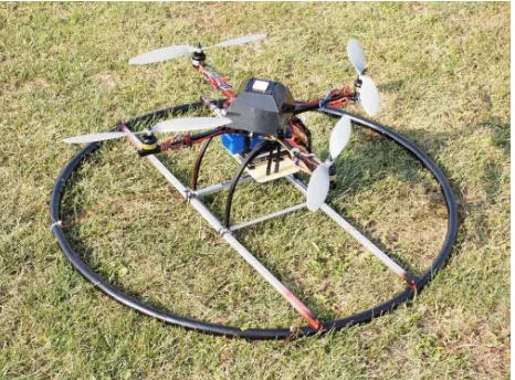
For this research a low-cost multicopter with four rotors based on the project ‘MikroKopter’1 was used (Fig. 1), see also (Briese and Glira, 2011).
Figure 1: UAV system based on the ‘MikroKopter’ project.
Multicopters usually have four (quadrocopter), six (hexacopter) or eight rotors (octocopter), which are arranged in a horizontal plane. For continually levelling the aircraft, a processing unit es-timates the inclination by evaluating the measurements of an IMU (Inertial Measurement Unit) consisting of three gyroscopes and three accelerometers. Next to the IMU some multicopter systems have further sensors on board. These are usually a magnetometer, an air pressure sensor, and a GNSS-receiver. Due to the use of all these sensors, multicopter systems typically behave very stable in the air and support the human operator to a high degree. Since these aircrafts became quite affordable over the last years, their use in research and commercial applications is currently increas-ing significantly.
1
www.mikrokopter.com
The ‘MikroKopter’ costs about 2000 $, offers an acceptable pay-load (250 g) for use in photogrammetry, and the on board soft-ware is open source. The availability of the programming code of the main processing unit was essential for the aim of direct georeferencing. Modifications of the source code allowed to syn-chronize the camera with the sensors and to save the raw data of these sensors. The sensor data was used to continually estimate position and orientation of the UAV. The position was derived by the measurements of the GNSS-receiver (‘u-blox LEA 6S’ with SBAS/EGNOS) and the air pressure sensor, the orientation by the measurement of the IMU and the magnetometer. The raw data of the IMU and the air pressure sensor can be recorded with a fre-quency of 20 Hz, whereas the data of the GNSS-receiver and the magnetometer is only available at a frequency of 2 Hz.
For image acquisition a digital compact camera (‘Canon Ixus 80 IS’) with a sensor resolution of 8 MP was chosen. The self-built camera mount is vibration-damped and connects the camera rigidly to the body of the UAV. It is restricted to nadir viewing. This results in an unknown, but constant mounting calibration.
Using the ‘Canon Hacker Development Kit’2to modify the firm-ware of the camera, the focus could be set permanently to infinity, and automatic shut down, as typical for consumer cameras, could be turned off. In order to reduce the image motion, a very short exposure time had to be defined (Fig. 2). For this study the im-ages were taken in a constant time interval of 5 s.
The camera was calibrated with a photogrammetric test field in a laboratory with a large number of control points. In order to study the influence of gravity on the sensor and/or the lens, the images for calibration were taken by rotating the camera along the horizontal pointing viewing axis. The subsequent analysis of the bundle block adjustment with free inner and outer orientation parameters for each individual camera rotation did not indicate a significant influence of gravity for the utilised camera. The cal-ibration procedure of all acquired calcal-ibration images resulted in residual errors (1 sigma) of≈0.2 px.
Figure 2: Example of an UAV (flying height: approx. 25m) image with an exposure time of 1/1000 s. Notice the low sun angle. The insert zooms to a control point used for evaluation. The control point ID is printed on an A4 paper.
2
3 DIRECT GEOREFERENCING
3.1 General
Direct georeferencing is the direct estimation of position and ori-entation of the camera with sensors on board of the aircraft (i.e., without using control points). The position is defined by the three coordinates of the projection center (X0, Y0, Z0) in a navigation frame. The orientation of the camera in the navigation frame can be described by the three rotation angles roll, pitch and yaw (r0, p0, y0).
Fig. 3 gives an overview of the available sensors on the UAV and which sensors can be integrated to obtain position and orientation of the camera. The interpolation at the exposure-times gives the position and the orientation of each image.
To improve the height measurements of the GNSS-receiver, the air pressure sensor was utilised. The WGS84-coordinates were transformed into the navigation frame with a seven-parameter transformation. More demanding, than the estimation of the posi-tion, was the derivation of the orientation from the measurements of the IMU and the magnetometer, which is described in the fol-lowing section.
Figure 3: Direct georeferencing of the images by integration of all available sensors on board of the UAV.
3.2 Estimation of orientation
The rotation anglesr, p, y[◦]are usually found by integrating the
measured rotation ratesωb
x, ωyb, ωbz[◦/s]of the gyroscopes over time. This works well for high-grade inertial sensors. However, the inertial sensors on the UAV are based on MEMS technology. They are small, lightweight, inexpensive, and consume very lit-tle power. Due to their fabrication process MEMS-sensors have large bias instabilities and high noise (El-Sheimy, 2009). Thus, the integration of the angular rates leads to large errors in the ro-tation angles already after a few seconds. To reduce this errors, absolute angle measurements are needed. They can be obtained for roll and pitch from the accelerometers and for yaw from the magnetometer.
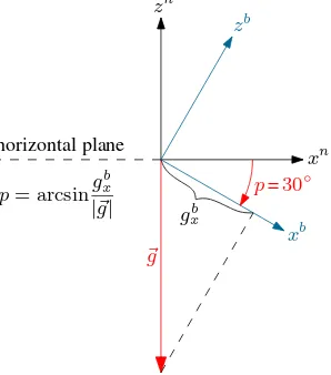
While the UAV is not moving (e.g., when the UAV is hanging above a defined waypoint) or is just moving very slowly, the three accelerometers can be used to estimate roll and pitch. On that condition, the accelerometers measure the three orthogonal com-ponentsgb
x, gby, gzbof the gravitational acceleration~g. For the sake of simplicity, this is shown in Fig. 4 just for the 2D-case. In fact, in this approach, the accelerometers are used as a tilt meter. Due to the vibrations on the UAV, before roll and pitch are computed,
the measured accelerations must be low-pass filtered with a cutoff frequency of 100 Hz or less.
The time frames where the UAV can assumed to me stable or constantly moving were determend on the actual observed accel-eration and rotation values. If for both values only low variations can be observed the UAV platform can be assumed to be on a fixed or continous moving position and orientation. Within all such time frames the accelerometers can be utilised for the drift compensation.
Figure 4: By measuring the components of the gravitational ac-celeration~gwith the accelerometers, the tilt angles roll and pitch can be estimated.
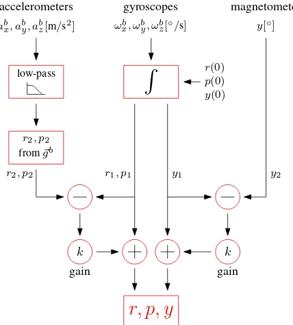
The integration of the gyroscopes, the accelerometers, and the magnetometer for the estimation of the three rotation anglesr, p
andy, is shown in Fig. 5. First, starting from the initial values
r(0), p(0)andy(0)the rotation ratesωb described above, the measured accelerations can be used to derive
r2 andp2, whereas the magnetometer measures directlyy2. At this point, the rotation angles from the gyroscopes can be com-pared to the rotation angles from the accelerometers and the mag-netometer. These differences are the error signals, which can be used to correct the rotation angles derived from the gyroscopes. The value of the gain factorkdefines how strong the stabilization of the integral should be. Ifkis set to 1, the rotation angles are completely derived by the accelerometers and the magnetometer. On the other hand, ifkis set to 0, the rotation angles are com-pletely derived by the gyroscopes. However, for0< k <1the advantages of all sensors can be combined. For the UAV used in this study, the gain factorkwas set to 2 %. It is noted thatkneed not be the same forr, pon the one hand, andyon the other hand.
For the presented approach the calculated rotation angles are dom-inated on short time scales by the measurements of the gyro-scopes, whereas the accelerometers and the magnetometer cor-rect the rotation angles over a long time scale.
3.3 Data Streams
The images taken are directly stored on the SD-Card of the cam-era. The navigation sensor data is downlinked via a Wi.232 con-nection and stored on a laptop harddisk. In professional kine-matic multi-sensor systems the GPS PPS signal is used for the synchronization of all data streams, which is, however, not avail-able for the described components.
gyroscopes
ωb
x, ωyb, ωzb[◦/s]
R
r(0)p(0) y(0)
y1
r2, p2 r1, p1
k k
magnetometer
y[◦]
y2
r, p, y
gain gain
low-pass
accelerometers
ab
x, aby, abz[m/s 2
]
r2, p2
from~gb
Figure 5: Estimation of rollr, pitchp, and yawy
at each triggering of the camera, which is fed into the downlink stream. The time lag between exposure and insertion of this sig-nal in the downlink stream was determined once by a photograph of the laptop screen were the downlinked navigation data stream was displayed in real time on the screen. Based on this simple procedure a time lag of 0.75 s±0.11 s could be estimated. This solution became possible with some minor adaptions of the open source MikroKopter flight control firmware.
4 EVALUATION
The quality of the exterior orientation computed by the process presented in section 3 can be determined in different ways. The navigation sensors can be mounted, independently of the UAV system with the camera on a different platform which is equipped with a high end position and orientation system. This provides reference data, which is directly of the same type as the acquired (low cost) sensor data. However, this is not the ordinary operating principle of the UAV. As the aim is the direct georeferencing of images, we compared it to position and orientation values deter-mined by indirect georeferencing, obtained from a bundle block adjustment.
The exterior orientations of a bundle block adjustment can act as an absolute reference, if systematic errors in the bundle block triangulation can be ruled out. Typical sources for that would be insufficient camera calibration or errors in the control points. The camera calibration was described above. Control points were measured using RTK GPS, providing an absolute accuracy (1 sigma) of≈2cm, with a relative accuracy below 2cm.
A test fligh was performed over a model aircraft field. Fig. 6 shows an orthophoto mosaic, created from the acuired imagery. A layout of 4x6 control points (circular shape, see also Fig. 2) was used for the test of direct geo-referencing.
The flight (cf. Figure 7) was organized along a predefined route, with waypoints. At each waypoint, the UAV remained stable for ≈10 seconds (user defined). Images were taken at a constant in-terval of 5 s and the focus was set to infinity. The flight lasted
5 m
5 m
Figure 6: Test area with 24 control points on a model aircraft field.
flight time 412 s
number of direct georeferenced photos 72 number of indirect georeferenced photos 53
trajectory∆X 34.7 m
trajectory∆Y 27.4 m
max. flight height above ground 25.5 m exposure time of the photos 1/1000 s
Table 1: Flight statistics.
take off landing photos
158 168 178 188
291500
291481.25 291462.5
291443.75 291425
19590 19615
19640
X
Y
[m]
Z
Figure 7: Trajektory of the waypoint flight. Due to a miscalibra-tion of the magnetometer the waypoint flight was stopped and the final flight and landing was performed manually.
for approximately seven minutes, and reached a height of 25 m above ground. Due to a problem with the calibration of the mag-netometer (new firmware version) the automated waypoint flight was interrupted and the following flight path (≈50 %) and land-ing was performed by manual remote control. Additional flight parameters are given in Tab. 1.
The aerial triangulation was performed using the program pack-age Orient/Orpheus developed at the Vienna University of Tech-nology. The adjustment led to a mean accuracy (1 sigma) of the image positions of 2.2 cm, 2.6 cm and 0.8 cm for the x-,y- and z-coordinate, respectively. The mean accuracy (1 sigma) of the rotation anglesr, p, yof all adjusted images are 0.075◦, 0.064◦
and 0.015◦. The mean accuracy of the x,y, and z control point
co-ordinates are 0.2 cm, 0.2 cm and 0.7 cm, respectively.
were compared to the bundle block results. The given mean val-ues of the differences could be found in similar magnitude for other flights over the same test field. The determined position offset resulted in values of -1.09 m, 0.36 m, and -1.40 m for the x-, y-x-, and z-coordinate. With the GPS receiver above the projection center these values do not come from the mounting (lever arm), but are rather attributed to the realization of the datum. The roll and nick angle offset was determined to be -0.12◦and -1.92◦,
respectively. These quantities can be interpreted as mounting cal-ibration with respect to their size. The yaw angle showed up a big offset value of -18.24◦, which was caused by the previously
mentioned error in the calibration of the magnetometer (cf. Table 2).
σ mean
r 0.91◦ 0.12◦
p 0.94◦ −1.92◦
y 2.34◦ −18.24◦
X 0.43m −1.09m
Y 0.57m 0.36m
Z 0.87m −1.40m
Table 2: Standard deviationσand mean of the differences be-tween direct and indirect georeferencing.
After the substraction of the mean differences the direct and indi-rect determined values were further studied. The Figures 8, 9 and 10 present individual comparision plots between the direct and in-direct georeferencing results. Fig. 8 shows the deviations for the
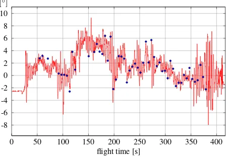
X coordinate, after subtraction of the mean. The pattern is re-peated very well, but some larger systematic offsets, e.g. at 350 s, occur. Fig. 9 shows that the quadrocopter is keeping the height during the flight more stable, than it is reported by the sensors. This differences may manly be introduced by air pressure varia-tions introduced by varying motor speed which was necessary to stabilize and navigate the UAV at the predefined flight path. Fi-nally, Fig. 10 shows that the roll angle variation during the flight is more than 14◦reported by the on board sensors, whereas the
aero-triangulation provides a range of 8◦. The on board sensors,
however, model a large portion of the variability of the reference data.
The standard deviation for roll and pitch differences, i.e. after subtracting the mean values from the differences is0.9◦, and
therefore well within the specifications of the sensors. The yaw of the camera could be determined less accurate (only integer val-ues are provided by the magnetometer and, as mentioned before, the gyroscope observations were not considered during the pro-cessing of the yaw angle of this data set), but still has an accuracy of 2◦. For the determination of the camera position the
stan-dard deviation is 0.43 m, 0.57 m, and 0.87 m for the x-, y-, and z-coordinates and is well below the expected accuracy of 1 m (cf. Table 2). Due to the subtraction of the mean, this estimation may be too optimistic. However, the evaluation is based on more than 50 photos.
5 CONCLUSIONS
UAV systems are a promising platform for close range airborne photogrammetry. Within this paper it could be demonstrated that the accuracy of on board devices of light weight (smaller than 1kg) UAV platforms can be used for direct georeferencing of the acquired imagery with a positional accuracy (1 sigma) below 1m meter, a nick and roll angle accuracy of smaller than 1◦and a yaw
accuracy smaller than 2.5◦. With the camera’s parameters and a
flying height of 25 m above ground (GSD 7 mm), this propagates
19595 19600 19605 19610 19615 19620 19625 19630
50 100 150 200 250 300 350 400 flight time [s]
[m]
Figure 8: Comparison of direct and indirect georeferencing for the x-coordinate. The red line represents the direct georeferenc-ing result, whereas the blue dots correspond to the indirect geo-referencing.
50 100 150 200 250 300 350 400 flight time [s]
[m]
160 165 170 175 180 185
Figure 9: Comparison of direct and indirect georeferencing for the z-coordinate. The red line represents the direct georeferenc-ing result, whereas the blue dots correspond to the indirect geo-referencing.
flight time [s]
[◦]
0 50 100 150 200 250 300 350 400 -8
-6 -4 -2 0 2 4 6 8 10
to planimetric offsets at the ground as follows. Roll and pitch at nadir: 44 cm; yaw at image corner: 1.3 m;Z at image corner: 1.1 m.
These results concerning the position (of the ‘projection center’) are, in general, in line with those given in Sec. 1.1. Compared to (Eisenbeiß, 2009) and (Eisenbeiß et al., 2009) the here presented results for the planimetric positioning are a bit worse, but gener-ally the sample for comparison is small. It is therefore difficult to attribute those differences either to the method of trajectory com-putation or the method of comparison. Like in (Haala et al., 2011) the expected accuracy derived from the antenna/receiver specifi-cation was reached for positioning. These papers, however, do not consider the estimation of the angular attitude, as it was done in this contribution. Compared to (Eugster and Nebiker, 2008) our real world examples based on standard low cost sensors con-firm their a-priori estimation of angular accuracy and their influ-ence of ground points.
While these values might already be sufficient for certain map-ping tasks, the observations used for direct georeferencing can be utilised in an integrated georeferencing of the acquired imagery. Without additional costs or equipment, the presented approach can considerably narrow down the search space in automatic im-age orientation and might support a bundle adjustment in the case of a significant amount of gross errors (e.g. mismatched tie points due to bad image texture). As (Haala et al., 2011) point out, ‘ver-tical images’ with deviations of the viewing axis from the nadir in the order of 30◦may occur for light weight UAVs.
It will further be investigated if the constant values for the “mount-ing calibration” can be verified. This would open up the estima-tion of these offset parameters on a small set of control points in the immediate vicinity of the take-off/landing site. As no ref-erences to angular accuracy of direct geo-referencing of light weight UAVs with on board sensors was found, the above accu-racy estimates should be further tested. With respect to applica-tions geomorphology on the one hand, and ecology on the other hand (M¨ucke et al., 2011), will be further explored, because both can profit form georeferenced vertical close range photogramme-try for monitoring purposes.
6 ACKNOWLEDGMENTS
The Ludwig Boltzmann Institute for Archaeological Prospection and Virtual Archaeology (archpro.lbg.ac.at) is based on an inter-national cooperation of the Ludwig Boltzmann Gesellschaft (A), the University of Vienna (A), the Vienna University of Technol-ogy (A), the Austrian Central Institute for MeteorolTechnol-ogy and Geo-dynamic (A), the office of the provincial government of Lower Austria (A), Airborne Technologies GmbH (A), RGZM-Roman-Germanic Central Museum Mainz (D), RA-Swedish National Her-itage Board (S), IBM VISTA-University of Birmingham (GB) and NIKU-Norwegian Institute for Cultural Heritage Research (N). The work was supported by the TransEcoNet project within the EU Central Europe program co-financed by the ERDF. This study was partly undertaken within the EU project NEWFOR, financed by the European Territorial Cooperation Alpine Space.
REFERENCES
Blaha, M., Eisenbeiß, H., Grimm, D. and Limpach, P., 2011. Di-rect georeferencing of UAVs. International Archives of the Pho-togrammetry, Remote Sensing and Spatial Information Sciences, Vol. XXXVIII-1/C22 UAV-g 2011, Conference on Unmanned Aerial Vehicle in Geomatics, Zurich, Switzerland.
Briese, C. and Glira, P., 2011. Reed mapping by unmanned aerial vehicles. Rhombos-Verlag, pp. 121–130.
Cramer, M., Stallmann, D. and Haala, N., 2000. Direct georef-erencing using GPS/Inertial exterior orientations for photogram-metric applications. International Archives of Photogrammetry and Remote Sensing. Vol. XXXIII, Part B3. Amsterdam.
Eisenbeiß, H., 2009. UAV Photogrammetry. PhD thesis, Institute of Geodesy and Photogrammetry, ETH Zurich, Switzerland.
Eisenbeiß, H., Stempfhuber, W. and Kolb, M., 2009. Genauigkeitsanalyse der 3D-Trajektorie von Mini-UAVs. DGPF Tagungsband 18/2009.
El-Sheimy, N., 2009. Emerging MEMS IMU and its impact on mapping applications. Photogrammetric Week 2009, Dieter Fritsch (Ed.).
Eugster, H. and Nebiker, S., 2008. Uav-based augmented mon-itoring - real-time georeferencing and integration of video im-agery with virtual globes. The International Archives of the Pho-togrammetry, Remote Sensing and Spatial Information Sciences, ISPRS Congress, Beijing, China, XXXVII. Part B1, 1229-1236.
Everaerts, J., 2008. The use of unmanned aerial vehicles (UAVs) for remote sensing and mapping. The International Archives of the Photogrammetry, Remote Sensing and Spatial Information Sciences, ISPRS Congress, Beijing, China, XXXVII. Part B1, 1187-1192.
Haala, N., Cramer, M., Weimer, F. and Trittler, M., 2011. Perfor-mance test on uav-based photogrammetric data collection. Inter-national Archives of the Photogrammetry, Remote Sensing and Spatial Information Sciences, Vol. XXXVIII-1/C22 UAV-g 2011, Conference on Unmanned Aerial Vehicle in Geomatics, Zurich, Switzerland p. 6.