RPAS AND TLS TECNIQUES FOR ARCHAEOLOGICAL SURVEY: THE CASE STUDY
OF THE ARCHAEOLOGICAL SITE OF ERACLEA MINOA (ITALY)
M. Lo Bruttoa, R. Sciortinoa, A. Garraffaa
a Dept. of Civil, Environmental, Aerospace, Materials Engineering (DICAM), University of Palermo, Italy
(mauro.lobrutto, rosanna.sciortino, alessandra.garraffa)@unipa.it
Commission II
KEYWORDS: Archaeological survey, Terrestrial Laser Scanner, RPAS, Photogrammetry, 3D Modelling.
ABSTRACT:
Digital documentation and 3D modelling of archaeological sites are important for understanding, definition and recognition of the values of the sites and of the archaeological finds. The most part of archaeological sites are outdoor location, but a cover to preserve the ruins protects often parts of the sites. The possibility to acquire data with different techniques and merge them by using a single reference system allows creating multi-parties models in which 3D representations of the individual objects can be inserted.
The paper presents the results of a recent study carried out by Geomatics Laboratory of University of Palermo for the digital documentation and 3D modelling of Eraclea Minoa archaeological site. This site is located near Agrigento, in the south of Sicily (Italy) and is one of the most famous ancient Greek colonies of Sicily. The paper presents the results of the integration of different data source to survey the Eraclea Minoa archaeological site. The application of two highly versatile recording systems, the TLS (Terrestrial Laser Scanning) and the RPAS (Remotely Piloted Aircraft System), allowed the Eraclea Minoa site to be documented in high resolution and with high accuracy. The integration of the two techniques has demonstrated the possibility to obtain high quality and accurate 3D models in archaeological survey.
1. INTRODUCTION
Digital documentation and 3D modelling of archaeological sites are important for understanding, definition and recognition of the values of the sites and of the archaeological finds.
In a digital documentation and 3D modelling project, the main goal is to produce an accurate and photo-realistic digital replica of the surveyed reality, to support activities like investigation, interpretation and at the same time the spread of Cultural Heritage artefacts.
Many approaches could be used for digital documentation and 3D modelling, mainly by photogrammetry and 3D scanning; Remondino (2011) gives a review of the benefits and drawbacks of photogrammetry and 3D scanning. The choice of the best approach depends on required accuracy, object dimensions, location constraints, system’s portability and usability, surface characteristics, working team experience, project’s budget, final goal, etc. (Remondino & Rizzi, 2010).
Today RPAS (Remotely Piloted Aircraft System) and TLS (Terrestrial Laser Scanning) survey are standard approach to produce high quality point cloud and 3D model in archaeological context with reduced execution times and great metric reliability. The capabilities of RPAS and TLS for the documentation of archaeological sites has been demonstrated in several different case studies (Lambers et al., 2007; Sauerbier & Eisenbeiss, 2010; Hendrickx et al., 2011; Lo Brutto et al., 2012; Guidi et al., 2014; Lo Brutto et. al., 2014; Galeazzi, 2016; Nikolakopoulos et al., 2016). The choice of which of these two techniques should be used is influenced by the logistic condition and site characteristics. However due to the inherent complexity of these sites, a multi-sensor approach is preferred for the 3D reconstruction and visualization of these environments in order to obtain high quality archaeological products (Torres-Martínez et al., 2015; Grussenmeyer et al., 2012; Xu et al., 2016). The possibility to acquire data with different techniques and merge them using a single reference system allows creating multi-parties models in which 3D representations of the individual
parties can be inserted permitting us to see a complete and almost-real 3D model.
The paper presents preliminary results carried out by Geomatics Laboratory of University of Palermo in the project “NEPTIS - ICT based solutions for augmented fruition and exploration of Cultural Heritage”. The project is financedby Italian Ministry of Education, University and Research and brings together several Universities, research centres and companies (Engineering spa, University of Palermo, University of Catania, National Research Council, IDS & Unitelm srl, Consortium PITecnoBio) with relevant expertise in Cultural Heritage management. The project focuses on cultural experience and cultural heritage exploitation defining and realizing an integrated system prototype to create services and applications supporting itineraries and cultural heritage exploitation. These itineraries would offer a medium to improve the knowledge of history, thought visualization techniques for indoor and in situ application. The validation of project results will take place on some Sicilian Cultural Heritage that will be study and document by the project partners. In this context, Geomatics Laboratory of University of Palermo has directed its activities towards the digital documentation and 3D modelling of Eraclea Minoa archaeological site. In fact, this archaeological site has been chosen as test site for the project.
The main goal of Geomatics Laboratory activities is to produce a high detailed 3D model of the site, using the most innovative survey techniques, and to arrange 3D data for the virtual reconstruction of the site. These data will be use also to yield physical real itineraries and navigation/exploration systems of virtually rebuilt environment for mobile devices such as smartphone and tablet.
phenomena, the covers protect a crucial of the site, the ancient theatre and two houses. The last two buildings show an exceptional state of preservation of the walls, not only the stone but also the high part of cob. These walls were covered with painted plaster, which remains the foundation of entrapment.
2. ERACLEA MINOA ARCHAEOLOGICAL SITE
The Eraclea Minoa archaeological site is located near Agrigento, in the south of Sicily (Italy), (Figure 1) and is one of the most famous ancient Greek colonies of Sicily. It is not possible to trace a precise outer perimeter of the site but it certainly occupied the summit part of a headland, known as “Capobianco”, and stretches out toward the sea to the Southwestern extremity.
Figure 1. Position of Eraclea Minoa archaeological site.
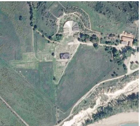
The site was built by Greek colonists in the sixth century BCE; today are visible only buildings ruins, the theatre and ruins of a circuit wall that contained the whole site (Figure 2).
Compared to other important archaeological sites of the Magna Graecia in Sicily the Eraclea Minoa archaeological site only in relatively recent times was studied by systematic archaeological excavation campaign. Professor De Miro (De Miro, 1958; De Miro, 1966) carried out a large-scale excavation campaigns that brought to light first the theatre and then the buildings ruins and ruins of the circuit wall between 1950 and 1960.
Figure 2. Area of Eraclea Minoa archaeological site.
Two layers of houses were established, respectively related to the Hellenistic period (Strato II - IV-III century BCE, same period of the theatre) and the Roman republican period (Strato I - II-I century BCE). The settlement of the Hellenistic and Romans houses has a city plan composed of "insulae", separated by parallel streets. The organization in blocks of houses framed by the north-south streets that intersect with the east-west streets follows the pattern of the previous phase. The settlement of Strato II consists of houses characterized by a simple plant: square structure, closed around a small atrium with a central courtyard. Two houses of Strato II, named “House A” and “House B”, were excavated. These buildings ruins are some of the most important historical and archaeological evidence of the site.
“House A” had one floor and a courtyard provided with a big tank in which the roof waters converged. To the north of the courtyard there was a domestic chapel (lararium), of which there are the quadrangular altars placed against the north-west corner and the aedicule for lares in the east wall. The floor of the room is earthenware decorated with white tiles; the walls retain the leftover of stucco decoration.
The “House B” had a higher floor with rooms destined to housing, whose debris (raw brick walls, slabs threshold, stucco, plaster, floor earthenware decorated and mosaic), in the collapse, they have filled the rooms of the ground floor.
The so-called settlement of Strato I, to be associated with the last occupation phase of the city in Roman-republican epoch, lies above the most ancient settlement of the Hellenistic age. It consists of houses generally constituted of two or more rooms gravitating onto a courtyard with fireplace. The walls are built with a base of chalky stone blocks and mudbrick walls (Figure 3).
Figure 3. Buildings ruins of settlement of Strato I.
The theatre was built in the inlet of a hillock, opening toward the sea, which borders, on the Northwestern side, the flatland of the city.
The circuit wall currently visible is datable to the last decades of the 4th century BCE even though it is still possible to see works of the 3th and 2th century BCE.
The settlement area, and in particular the two best preserved old houses (A and B), were surveyed to produce the 3D model of the mainly part of the Eraclea Minoa archaeological site.
3. METODOLOGY
Due to the complexity of the morphology of this site, RPAS and TLS are employed to provide a complete digitally reconstructed heritage scenario. As described above, the survey of this site needs the use of different geomatics techniques, therefore a topographic survey have been the basic start point of all operations.
A topographical network, constituted of five stations, was measured using both total station and GNSS systems and was used to establishing a common reference frame between RPAS and TLS measurements. This network is fundamental for the correct data integrations especially in situation (like this) where no overlap exist between RPAS and TLS data.
The total station, a Leica TCR 307, was used to measure the coordinates of topographic network points and laser scanner targets (Figure 4). Laser scanner targets were put inside “House A” and “House B” and used for laser scanner point cloud registration. A local reference system was used for total station measurements.
Figure 4. Topographic survey with total station Leica TCR 307.
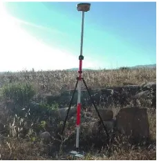
The GNSS, a Topcon HiperV dual-frequency GNSS receiver, was used to measure by a static survey the coordinates of the topographic network points and by a NRTK (Network-based Real Time Kinematic) survey, the photogrammetric targets (Figure 5). The photogrammetric targets were put in the settlement area and were used for image orientation in RPAS survey; a total of 36 well-distributed square targets (20 cm x 20 cm) were measured. The static survey and the NRTK survey were performed using the data from the Italian Continuously Operating Reference Stations (CORS) NetGEO. The GNSS measurements were georeferenced in the Italian national geodetic reference system RDN2008-ETRF2000 using the UTM projection.
Figure 5. NRTK survey with Topcon HiperV GNSS receiver.
To link together the total station and the GNSS measurements 3D roto-traslate parameters were calculated between the local reference system and the geodetic reference system using the topographic network coordinates. These topographic points have been measured both in the two reference systems. In this way it’s possible to link together the two datasets and to work with local reference system or geodetic reference system according to the need.
The main steps of the 3D data acquisition were: a) RPAS data acquisition of the settlement area;
b) TLS data acquisition of the two “House A” and “House B”.
3.1. RPAS data acquisition
The area covered by the flights was only the one of the settlement. It has an extent of approximately 1.5 hectares (about 150 m x 100 m). The RPAS acquisition has been realized using an Aibot X6 V2 produced by Aibotix GmbH (Figure 6). The Aibot X6 V2 is a multi-rotor with six electric powered rotor blades and a carbon fiber reinforced polymer housing. The aircraft is able to fly in manual, assisted or autonomous mode and to take-off and to land automatically. Some technical details can be seen in the table 1. The system was equipped with a mirrorless digital camera Olympus PEN E-PL5 with a lens of 17 mm.
Figure 6. The hexacopter Aibot X6 V2 by Aibotix.
Table 1. Technical specifications of Aibot X6 V2.
The flight planning was performed by flight mission package AiProFlight by Aibotix GmbH. The flight mission was planned taking into account a flight high over ground of 40 m, a forward and side overlap of 70% and a groundspeed equal to 1.5 m/s. The flight mission was also planned in autonomous flight mode. Image acquisition was planned in stop mode (Eisenbeiss & Sauerbier, 2011) constraining the system to fly to predefined waypoints, to stop at these locations and to take the images. With this approach 116 waypoints, split in 10 strips, were
W e ight 3 .4 Kg
Le ngt h/ W idt h/ H e igt h 1 .0 5 m x 1 .0 5 m x 0 .4 5 m
Pa y loa d 2 Kg
Ope ra t ion ra nge 1 Km
M a x im um re la t iv e he ight 5 0 0 m
Flight t im e 2 0 m in
M a x spe e d 4 0 k m / h
W ind re sist a nce 1 0 m / s
needed to cover the whole area (Figure 7); due to the limited endurance of the system, the flight mission was split in three flights of about 10’ each one.
Figure 7. Flight plan of the area of interest.
Taking into account the flight and the camera parameters a Ground Sampling Distance (GSD) of about 8 mm was obtained for the images.
Image orientation was carried out by PhotoScan Professional Edition package. This package is produced by Agisoft LLC and provides a sequence of automatic steps for image orientation and image matching; moreover, PhotoScan allows to extract 3D models with a very high level of detail and ortho-images using Structure from Motion (SfM) approach and dense stereo-matching algorithms.
For image orientation 18 targets were used as Ground Control Points (GCP); the remaining 18 targets were used as Check Points (CP) to evaluate the accuracy of the process (Figure 8).
Figure 8. GCP (in green) and CP (in blue) layout on the area of interest.
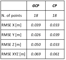
The “optimization” procedure, implemented in PhotoScan to perform bundle adjustment and camera calibration, was used to improve the internal and external camera orientation parameters estimate during the SfM procedure. The table 2 shows the RMSE of GCP and CP residuals obtained after the “optimization” procedure.
The dense image matching was then carried out to produce a very detailed 3D model of the settlement area of the site. To obtain a very high level of detail, the dense image matching process in PhotoScan was performed using “Ultra High” quality setting. With this setting the PhotoScan processes original
images (no image size downscaling were applied) to obtain the most detailed and accurate geometry of the object. From the dense point cloud a texture 3D model were then obtained (Figure 9).
Table 2. RMSE of GCP and CP residuals.
Figure 9. 3D model of the area of interest.
3.2. TLS data acquisition
A TLS survey was used to acquire geometric data of the covered area of morphological complex “House A” and “House B”. These geometric data were recorded from different scan positions because the two houses are composed of little rooms with a very low inter-visibility because of the tall walls. The laser scanning survey was carried out to produce a point cloud of the areas of interest with an average sampling step of about 3 mm.
The choice of the instrumental resolution usually is done on a case-by-case basis, according to the articulation more or less complex of the surveyed object. Simple geometries may be choosen to recognize the object generating sparse clouds. Instead, if the object of the survey is complex, you can decrease the sampling step thickening the number of points per unit area. However, increasing the number of points you are likely to make the high computational cost. Beside the choice of low-density scans could lead not only, in a bad detection of very articulated structures, but also in a bad identification of targets that make possible the recording of different clouds.
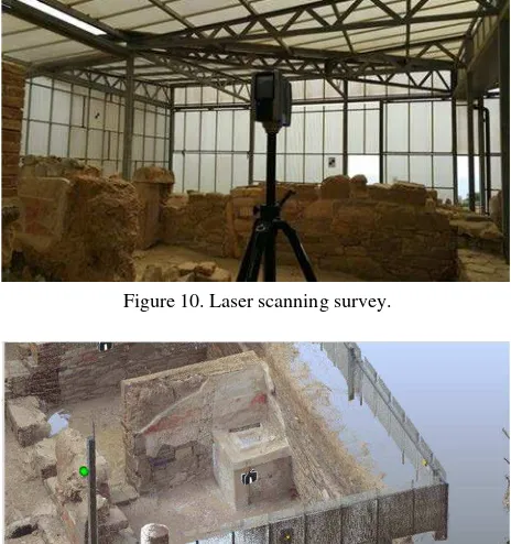
The laser scanner acquisition was performed by the phase-shift laser scanner Faro Focus 3D (Figure 10). Since the area to be detected has a limited extension (20 m x 10 m), but because of the presence of a large amount of shadow zones between one scan and the next due to the presence of high walls which delimit very small rooms, it is preferred to use an instrumental resolution of ¼ (6 mm to 10 m). Twenty-one scans were made, one for each of the 16 rooms plus 5 scans from high points to allow the survey of the heads of the walls.
Planar targets and spherical targets were used to support and to check the point clouds registration (Figure 11). Two planar targets were positioned on each wall (for a total of 8 targets); ten spherical targets on the metal pillars that support the roof,
GCP CP
N. of points 18 18
RMSE X [m] 0.039 0.033
RMSE Y [m] 0.026 0.039
RMSE Z [m] 0.050 0.033
distributed to see at least 5 target from each scan. The planar targets, measured with total station, may have the dual role of help point clouds registration process and georeference the data in the local reference system.
Figure 10. Laser scanning survey.
Figure 11. A detail of scan and targets positions.
The point cloud processing was done with Scene package. The automatic point cloud registration gives very good results; a RMSE (XYZ) of about ±3 mm was calculated from laser scanner targets residuals.
The use of laser scanners in archaeology has suffered some setback due both to the lack of reliable information on the colour value, the difficulty is to easily detect the horizontal surfaces of the archaeological deposit. To demonstrate this in the figure 12 are shown the negative effects of solar exposure not homogeneous in the textured 3D model. In this case, the laser scanner records a chromatic variation that in reality does not exist.
Figure 12. Point cloud produced from laser scanner survey for the two houses.
4. RESULTS
The final stage of this preliminary work consists in the merging of TLS and RPAS survey in a common reference system to create a continuous 3D model of the site without cover (Figure 13).
The two 3D models, despite the complex morphology of the site and the different level of detail, show a very high geometric agreement. Also, thanks to the topographical network, has obtained a good continuity between the discover and covered parts although the spatial resolution was not identical.
Unfortunately, the quality of the texture was reduced from the vegetation that covers a wild zone of the archaeological site. The data from laser scanner, however, provide a texture that is not compatible with the purposes of NEPTIS project.
The RGB colour parameter to be given to the cloud point is the weak point for the laser scanner applications in archaeology, due to the poor ability to correctly distinguish the limits and the surface characteristics of the different stratigraphic levels.
Figure 13. Integration of the RPAS and TLS 3D data in the same 3D model for a small part of the settlement.
The two insulae, “House A” and “House B”, need also to be surveyed with terrestrial close range photogrammetric technique; this data acquisition could allow obtaining a photo-realistic 3D models using high-resolution images.
It is important to underline that the level of detail of the meshes was proportional to the aim of documenting the site (Pierdicca et al., 2016). However, different level of details have been implemented in order to guarantee the portability of the model in different platforms (e.g. desktop application, web, mobile, etc.).
5. CONCLUSIONS
The paper presents the results of the integration of different data sources to survey the Eraclea Minoa archaeological site. The application of two highly versatile recording systems, the TLS and the RPAS, has been allowed the Eraclea Minoa site to be documented in high resolution and with high accuracy in about one week of fieldwork. The arrangement of the two techniques aims to optimize the advantages of high quality 3D models construction and supporting the visual quality of the generated 3D digital model.
The approach proposed in this paper has shown that accurate point clouds can be delivered both from laser scanner and from dense image matching, and thus merged for documentation in cultural heritage. To ensure the accurate merging of the different datasets, an accurate network of topographic points well distributed on the study area is required.
to operate an integration of the data offered by the laser scanning survey.
These models of Eraclea Minoa are a good starting point for a multi-level architectural, structural, and functional study of the site.
ACKNOWLEDGEMENTS
This work is part of “NEPTIS – ICT-based solutions for augmented fruition and exploration of Cultural Heritage” project.
The authors are grateful to the “Soprintendenza per i Beni Archeologici” di Agrigento to allow the RPAS and TLS survey and to Ing. Maria Grazia Spera and Ing. Claudia Pipitone for the collaboration during the survey.
REFERENCES
De Miro, E., 1958. Heraclea Minoa. Scavi eseguiti negli anni 1955-56-57, Notizie Scavi e Antichità, 1958.
De Miro, E., 1966. Heraclea Minoa. Risultati archeologici e storici dei primi scavi sistematici nell’area dell’abitato, Kokalos, XII, 1966.
Eisenbeiss, H., Sauerbier, M., 2011. Investigation of UAV systems and flight modes for photogrammetric applications. The Photogrammetric Record, 26(136), pp. 400–421.
Galeazzi, F., 2016. Towards the definition of best 3D practices in archaeology: Assessing 3D documentation techniques for intra-site data recording. Journal of Cultural Heritage, 17, pp. 159–169
Grussenmeyer, P., Alby, E., Landes, T., Koehl, M., Guillemin, S., Hullo, J. F., Assali, P., and Smigiel, E., 2012. Recording approach of heritage sites based on merging point clouds from high resolution photogrammetry and terrestrial laser scanning, Int. Arch. Photogramm. Remote Sens. Spatial Inf. Sci., XXXIX-B5, pp. 553-558, doi:10.5194/isprsarchives-XXXIX-B5-553-2012.
Guidi, G., Russo, M., Angheleddu, D., (2014). 3D survey and virtual reconstruction of archeological sites, Digital Applications in Archaeology and Cultural Heritage, 1(2), pp. 55-69, http://dx.doi.org/10.1016/j.daach.2014.01.001
Hendrickx, M., Gheyle, W., Bonne, J., Bourgeois, J., De Wulf, A., Goossens, R., 2011. The use of stereoscopic images taken from a microdrone for the documentation of heritage – An example from the Tuekta burial mounds in the Russian Altay, Journal of Archaeological Science, 38(11), pp. 2968-2978, http://dx.doi.org/10.1016/j.jas.2011.06.013.
Lambers K., Eisenbeiss H., Sauerbier M., Kupferschmidt D., Gaisecker T., Sotoodeh S., Hanusch T., 2007. Combining photogrammetry and laser scanning for the recording and modelling of the Late Intermediate Period site of Pinchango Alto, Palpa, Peru. Journal of Archaeological Science, 34(10), pp. 1702–1712, doi:org/10.1016/j.jas.2006.12.008
Lo Brutto, M., Borruso, A., D'Argenio, A., 2012. UAV Systems for Photogrammetric Data Acquisition of Archaeological Sites. International Journal of Heritage in the Digital Era, Vol. 1, Supplement 1, pp. 7-14, doi: 10.1260/2047-4970.1.0.1.
Lo Brutto, M., Garraffa, A., Meli, P., 2014. UAV platforms for cultural heritage survey: first results. ISPRS Ann. Photogramm. Remote Sens. Spatial Inf. Sci., II-5, pp. 227-234. doi: 10.5194/isprsannals-II-5-227-2014.
Nikolakopoulos, K.G., Soura, K., Koukouvelas, I.K., Argyropoulos, N.G., 2016. UAV vs classical aerial photogrammetry for archaeological studies, Journal of Archaeological Science, In Press, Available online 20 September 2016, http://dx.doi.org/10.1016/j.jasrep.2016.09.004.
Pierdicca, R.,Frontoni, E., Malinverni, E.S., Colosi, F., Orazi, R., 2016. Virtual reconstruction of archaeological heritage using a combination of photogrammetric techniques: Huaca Arco Iris, Chan Chan, Peru. Digital Applications in Archaeology and
Cultural Heritage, 3, pp. 80–90,
http://dx.doi.org/10.1016/j.daach.2016.06.002
Remondino, F., Rizzi, A., 2010. Reality-based 3D documentation of natural and cultural heritage sites -Techniques, problems, and examples. Applied Geomatics, 2(3), pp. 85–100.
Remondino, F., 2011. Heritage recording and 3D modeling with photogrammetry and 3D scanning. Remote Sensing, 3, pp. 1104–1138.
Sauerbier, M., Eisenbeiss, H., 2010. UAVs for the documentation of archaeological excavations. Int. Arch. Photogramm. Remote. Sens. Spat. Inf. Sci., XXXVIII (Part 5), pp. 526–531.
Torres-Martínez, J. A., Seddaiu, M., Rodríguez-Gonzálvez, P., Hernández-López, D., González-Aguilera, D., 2015. A multi-data source and multi-sensor approach for the 3D reconstruction and visualization of complex archaeological site: the case study of Tolmo de Minateda. Int. Arch. Photogramm. Remote Sens. Spatial Inf. Sci., XL-5/W4, pp. 37-44, doi:10.5194/isprsarchives-XL-5-W4-37-2015, 2015.