LAMPIRAN 1
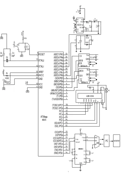
GAMBAR RANGKAIAN LENGKAP
10 k +5V 1 2 S1 GND GND C1 4,7µF C3 22pF C2 22pF Q1 +5V R1 100Ω C4
100 µF
GND +5V GND RESET XTAL2 XTAL1 AREF AVCC GND VCC GND 9 12 13 32 30 31 10 11 33 34 35 36 3 2 1 29 28 27 26 25 37 38 39 8 7 6 5 4 24 23 22 21 20 19 18 17 16 15 14 (ADC7)PA7 (ADC6)PA6 (ADC5)PA5 (ADC4)PA4 (ADC3)PA3 (ADC2)PA2 (ADC1)PA1 40 (ADC0)PA0 (SCK)PB7 (MISO)PB6 (MOSI)PB5 (SS)PB4 (AIN/INT2)PB3 (AIN0/OC0)PB2 (T1)PB1 (T0/XCK)PB0 (TOSC2)PC7 (TOSC1)PC6 PC5 PC4 PC3 PC2 (SDA)PC1 (SCL)PC0 (OC2)PD7 (ICP)PD6 (OC1A)PD5 (OC1B)PD4 (INT1)PD3 (INT0)PD2 (TXD)PD1 (RXD)PD0 14
7 8 9 10 11 12 13 4 5 6 2 16
3 1 15 R S R W E D B 7 D B 6 D B 5 D B 4 V c c V B 0 V E E V S S V B 1 Vcc
LCD 2 X 16 R1 R2 14 13 Vcc 16 +5V 1 3 4 5 T1OUT R1IN 11 12T1IN R1OUT +5V 2 6 Vs+ Vs-GND 15 C1+ C1-C2+ C2-MAX232
1 µ F
1 µ F
1 PC MONITOR 5 Rx Tx CS MOSI SCK Vcc GND T+ T-MAX6675
0,1 µF
DB9
+5V
CBYP
0, 1 µF
Ip IP+ IP+ IP-VCC VIOUT FILTER GND 1 2 3 4 5 6 7 8 VOUT Rf 2kO R1 10kO CF 1nF D1 1N4448W C1 nF 1 1N5392 1N5392 10µF 1K 1K Vin
1 µ F 1 µ F
ATMega 8535 ACS712 CS MOSI SCK Vcc GND T+
T-0,1 µF
LAMPIRAN 2
PROGRAM PADA MIKROKONTROLER
This program was created by the CodeWizardAVR V3.12 Standard Automatic Program Generator
© Copyright 1998-2014 Pavel Haiduc, HP InfoTech s.r.l. http://www.hpinfotech.com
Project : Version :
Date : 6/18/2015 Author :
Company : Comments:
Chip type : ATmega8535 Program type : Application
AVR Core Clock frequency: 16.000000 MHz Memory model : Small
External RAM size : 0 Data Stack size : 128
*******************************************************/
#include <mega8535.h> #include <stdio.h> #include <spi.h> #include <delay.h>
// 1 Wire Bus interface functions #include <1wire.h>
// DS1820 Temperature Sensor functions #include <ds1820.h>
// Alphanumeric LCD functions #include <alcd.h>
// Declare your global variables here
// Standard Input/Output functions #include <stdio.h>
// Voltage Reference: AVCC pin
#define ADC_VREF_TYPE ((0<<REFS1) | (1<<REFS0) | (1<<ADLAR))
// Read the 8 most significant bits // of the AD conversion result
ADMUX=adc_input | ADC_VREF_TYPE;
// Delay needed for the stabilization of the ADC input voltage delay_us(10);
// Start the AD conversion ADCSRA|=(1<<ADSC);
// Wait for the AD conversion to complete while ((ADCSRA & (1<<ADIF))==0); ADCSRA|=(1<<ADIF);
return ADCH; }
unsigned int acs712 (void) {
unsigned char cnt; unsigned int arus; arus = 0;
for (cnt = 0; cnt < 50; cnt++) {
arus = arus + read_adc(0); }
arus = arus / 50; return arus; }
unsigned int acs_712 (void) {
unsigned char cnt; unsigned int arus; arus = 0;
for (cnt = 0; cnt < 50; cnt++) {
arus = arus + read_adc(2); }
arus = arus / 50; return arus; }
unsigned int vin (void) {
unsigned char cnt; unsigned int v; v = 0;
for (cnt = 0; cnt < 50; cnt++) {
v = v + read_adc(1); } v = v / 50;
}
// SPI functions #include <spi.h>
unsigned int thermo (void) {
unsigned int th, xkar; th = spi(xkar); th = th << 8; th = th | spi(xkar); return th;
}
void main(void) {
// Declare your local variables here unsigned char buf[33];
unsigned int i712, i_712, vs, it, th, thl, thh;
// Input/Output Ports initialization // Port A initialization
// Function: Bit7=In Bit6=In Bit5=In Bit4=In Bit3=In Bit2=In Bit1=In Bit0=In DDRA=(0<<DDA7) | (0<<DDA6) | (0<<DDA5) | (0<<DDA4) | (0<<DDA3) | (0<<DDA2) | (0<<DDA1) | (0<<DDA0);
// State: Bit7=T Bit6=T Bit5=T Bit4=T Bit3=T Bit2=T Bit1=T Bit0=T PORTA=(0<<PORTA7) | (0<<PORTA6) | (0<<PORTA5) | (0<<PORTA4) | (0<<PORTA3) | (0<<PORTA2) | (0<<PORTA1) | (0<<PORTA0);
// Port B initialization
// Function: Bit7=Out Bit6=In Bit5=Out Bit4=Out Bit3=In Bit2=In Bit1=In Bit0=In
DDRB=(1<<DDB7) | (0<<DDB6) | (1<<DDB5) | (1<<DDB4) | (0<<DDB3) | (0<<DDB2) | (0<<DDB1) | (0<<DDB0);
// State: Bit7=0 Bit6=T Bit5=0 Bit4=0 Bit3=T Bit2=T Bit1=T Bit0=T PORTB=(0<<PORTB7) | (0<<PORTB6) | (0<<PORTB5) | (0<<PORTB4) | (0<<PORTB3) | (0<<PORTB2) | (0<<PORTB1) | (0<<PORTB0);
// Port C initialization
// Function: Bit7=In Bit6=In Bit5=In Bit4=In Bit3=In Bit2=In Bit1=In Bit0=In DDRC=(0<<DDC7) | (0<<DDC6) | (0<<DDC5) | (0<<DDC4) | (0<<DDC3) | (0<<DDC2) | (0<<DDC1) | (0<<DDC0);
// Port D initialization
// Function: Bit7=In Bit6=In Bit5=In Bit4=In Bit3=In Bit2=In Bit1=In Bit0=In DDRD=(0<<DDD7) | (0<<DDD6) | (0<<DDD5) | (0<<DDD4) | (0<<DDD3) | (0<<DDD2) | (0<<DDD1) | (0<<DDD0);
// State: Bit7=T Bit6=T Bit5=T Bit4=T Bit3=T Bit2=T Bit1=T Bit0=T PORTD=(0<<PORTD7) | (0<<PORTD6) | (0<<PORTD5) | (0<<PORTD4) | (0<<PORTD3) | (0<<PORTD2) | (0<<PORTD1) | (0<<PORTD0);
// Timer/Counter 0 initialization // Clock source: System Clock // Clock value: Timer 0 Stopped // Mode: Normal top=0xFF // OC0 output: Disconnected
TCCR0=(0<<WGM00) | (0<<COM01) | (0<<COM00) | (0<<WGM01) | (0<<CS02) | (0<<CS01) | (0<<CS00);
TCNT0=0x00; OCR0=0x00;
// Timer/Counter 1 initialization // Clock source: System Clock // Clock value: Timer1 Stopped // Mode: Normal top=0xFFFF // OC1A output: Disconnected // OC1B output: Disconnected // Noise Canceler: Off
// Input Capture on Falling Edge // Timer1 Overflow Interrupt: Off // Input Capture Interrupt: Off // Compare A Match Interrupt: Off // Compare B Match Interrupt: Off
TCCR1A=(0<<COM1A1) | (0<<COM1A0) | (0<<COM1B1) | (0<<COM1B0) | (0<<WGM11) | (0<<WGM10);
TCCR1B=(0<<ICNC1) | (0<<ICES1) | (0<<WGM13) | (0<<WGM12) | (0<<CS12) | (0<<CS11) | (0<<CS10);
TCNT1H=0x00; TCNT1L=0x00; ICR1H=0x00; ICR1L=0x00; OCR1AH=0x00; OCR1AL=0x00; OCR1BH=0x00; OCR1BL=0x00;
ASSR=0<<AS2;
TCCR2=(0<<WGM20) | (0<<COM21) | (0<<COM20) | (0<<WGM21) | (0<<CS22) | (0<<CS21) | (0<<CS20);
TCNT2=0x00; OCR2=0x00;
// Timer(s)/Counter(s) Interrupt(s) initialization
TIMSK=(0<<OCIE2) | (0<<TOIE2) | (0<<TICIE1) | (0<<OCIE1A) | (0<<OCIE1B) | (0<<TOIE1) | (0<<OCIE0) | (0<<TOIE0);
// External Interrupt(s) initialization // INT0: Off
// INT1: Off // INT2: Off
MCUCR=(0<<ISC11) | (0<<ISC10) | (0<<ISC01) | (0<<ISC00); MCUCSR=(0<<ISC2);
// USART initialization
// Communication Parameters: 8 Data, 1 Stop, No Parity // USART Receiver: On
// USART Transmitter: On // USART Mode: Asynchronous // USART Baud Rate: 9600
UCSRA=(0<<RXC) | (0<<TXC) | (0<<UDRE) | (0<<FE) | (0<<DOR) | (0<<UPE) | (0<<U2X) | (0<<MPCM);
UCSRB=(0<<RXCIE) | (0<<TXCIE) | (0<<UDRIE) | (1<<RXEN) | (1<<TXEN) | (0<<UCSZ2) | (0<<RXB8) | (0<<TXB8);
UCSRC=(1<<URSEL) | (0<<UMSEL) | (0<<UPM1) | (0<<UPM0) | (0<<USBS) | (1<<UCSZ1) | (1<<UCSZ0) | (0<<UCPOL);
UBRRH=0x00; UBRRL=0x67;
// Analog Comparator initialization // Analog Comparator: Off
// The Analog Comparator's positive input is // connected to the AIN0 pin
// The Analog Comparator's negative input is // connected to the AIN1 pin
ACSR=(1<<ACD) | (0<<ACBG) | (0<<ACO) | (0<<ACI) | (0<<ACIE) | (0<<ACIC) | (0<<ACIS1) | (0<<ACIS0);
// ADC initialization
// ADC Clock frequency: 125.000 kHz // ADC Voltage Reference: AVCC pin // ADC High Speed Mode: Off
// ADC Auto Trigger Source: ADC Stopped // Only the 8 most significant bits of
ADMUX=ADC_VREF_TYPE;
ADCSRA=(1<<ADEN) | (0<<ADSC) | (0<<ADATE) | (0<<ADIF) | (0<<ADIE) | (1<<ADPS2) | (1<<ADPS1) | (1<<ADPS0);
SFIOR=(1<<ADHSM) | (0<<ADTS2) | (0<<ADTS1) | (0<<ADTS0);
// SPI initialization // SPI Type: Master
// SPI Clock Rate: 125.000 kHz // SPI Clock Phase: Cycle Start // SPI Clock Polarity: Low // SPI Data Order: MSB First
SPCR=(0<<SPIE) | (1<<SPE) | (0<<DORD) | (1<<MSTR) | (0<<CPOL) | (0<<CPHA) | (1<<SPR1) | (1<<SPR0);
SPSR=(0<<SPI2X);
// TWI initialization // TWI disabled
TWCR=(0<<TWEA) | (0<<TWSTA) | (0<<TWSTO) | (0<<TWEN) | (0<<TWIE);
// 1 Wire Bus initialization // 1 Wire Data port: PORTC // 1 Wire Data bit: 0
// Note: 1 Wire port settings are specified in the
// Project|Configure|C Compiler|Libraries|1 Wire menu. w1_init();
// Alphanumeric LCD initialization // Connections are specified in the
// Project|Configure|C Compiler|Libraries|Alphanumeric LCD menu: // RS - PORTB Bit 0
// RD - PORTB Bit 1 // EN - PORTB Bit 2 // D4 - PORTC Bit 4 // D5 - PORTC Bit 5 // D6 - PORTC Bit 6 // D7 - PORTC Bit 7 // Characters/line: 16 lcd_init(16);
lcd_init(16); lcd_gotoxy(0,0);
lcd_putsf("I(Amp), V(Volt)");
while (1) {
i712 = i712 - 95 ; i_712 = i_712 - 120;
if (i712 > 250) i712 = 0; if (i_712 > 250) i_712 = 0;
it = i_712 + i712; it = (it * 13) / 12;
vs = vin()* 9/4; th = thermo;
lcd_gotoxy(0,0);
sprintf(buf,"I:%02u.%01u V:%02u.%01u",it/10, it%10, vs/10, vs%10);
lcd_puts(buf); lcd_gotoxy(0,1);
sprintf(buf,"Ihermo: %05",th); lcd_puts(buf);
thl = th; thh = th;
thl = th & 0x00ff; thh = th >> 8;
delay_ms(10); putchar('I'); putchar(it); putchar('V'); putchar(vs);
putchar{'T'); putchar(thl); putchar(thh);
Program Visual Basic
Private Sub Command1_Click()
MSComm1.PortOpen = False
Close intHandle
End
End Sub
Private Sub Command3_Click()
Print #intHandle, "There will be a new line after this!"
Print #intHandle, "Last line in file!"; '<- Notice semicolon.
End Sub
Private Sub Form_Load()
If MSComm1.PortOpen = False Then
MSComm1.PortOpen = True
MSComm1.RThreshold = 2
MSComm1.NullDiscard = False
MSComm1.InputMode = comInputModeText
End If
End Sub
Private Sub MSComm1_OnComm()
Dim vkar, cmd As String
' Dim cmd As Byte
Dim arus, t1l, t1h, t2l, t2h tegangan As Byte
If MSComm1.CommEvent = 2 Then
vkar = MSComm1.Input
cmd = Mid$(vkar, 1, 1)
arus = Asc(Mid$(vkar, 2, 1))
Text2.Text = arus / 10
End If
If cmd = "V" Then
tegangan = Asc(Mid$(vkar, 2, 1))
Text1.Text = tegangan / 10
End If
If cmd = "T1" Then
t1l = Asc(Mid$(vkar, 2, 1))
t1h = Asc(Mid$(vkar, 2, 1))
t1 = t1h
t1 = SHL (t1h,8)
t1 = t1 OR t1l
Text3.Text = t1
End If
If cmd = "T2" Then
t2l = Asc(Mid$(vkar, 2, 1))
t2h = Asc(Mid$(vkar, 2, 1))
t2 = t2h
t2 = SHL (t2h,8)
t2 = t2 OR t2l
Text4.Text = t2
End If
End If
End Sub
Private Sub Timer1_Timer()
Dim intHandle As Integer
Text3.Text = Time$()
Text4.Text = Time$()
Open "D:\vi_data\vi_data.txt" For Append As intHandle
Open "C:\Users\jerri_doc\jerri.txt" For Append As intHandle
Print #intHandle, Text1.Text, Text2.Text, Text3.Text, Text4.Text Chr(13),
Chr(10)
Close intHandle
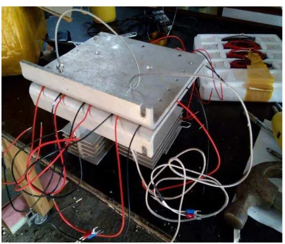
LAMPIRAN 3
GAMBAR SISTEM PERALATAN
1. Peltier TEC1-12706
3. Lensa Fresnel