IEEE P802.11
Wireless LANs
Specification Framework for TGac
Date: 2011-01-19Author(s):
Name Affiliation Address Phone email
Robert Stacey Intel 2111 NE 25OR 97124, USAth Ave, Hillsboro 503-724-0893 [email protected]
Eldad Perahia Intel 2111 NE 25OR 97124, USAth Ave, Hillsboro [email protected]
Adrian
Stephens Intel [email protected]
Assaf Kasher Intel [email protected]
Solomon
Trainin Intel [email protected]
Michelle Gong Intel [email protected]
Raja Banerjea Marvell 5488 Marvell Lane, Santa Clara CA, 95054 408.222.3713 [email protected]
Hongyuan
Zhang Marvell 5488 Marvell Lane, Santa Clara CA, 95054 408.222.1837 [email protected] Sudhir
Srinivasa Marvell 5488 Marvell Lane, Santa Clara CA, 95054 [email protected] Yong Liu Marvell 5488 Marvell Lane, Santa Clara CA, 95054 [email protected]
Harish
Ramamurthy Marvell [email protected]
Ning Zhang Atheros 1700 Technology Drive,San Jose, CA 95110 408-773-5363 [email protected]
Youhan Kim Atheros 1700 Technology Drive,San Jose, CA 95110 Youhan,Kim@atheros,com
William
McFarland Atheros 1700 Technology Drive,San Jose, CA 95110 [email protected] Kai Shi Atheros 1700 Technology Drive,San Jose, CA 95110 [email protected]
Joshua Zhao Atheros 1700 Technology Drive,San Jose, CA 95110 [email protected]
Qifan Chen Atheros 1700 Technology Drive,San Jose, CA 95110 [email protected]
James Cho Atheros 1700 Technology Drive,San Jose, CA 95110 [email protected]
Allert Van
Zelst Qualcomm Netherlands [email protected]
Richard Van
Nee Qualcomm Netherlands [email protected]
Santosh
Abraham Qualcomm San Diego, USA [email protected]
Hemanth
Sampath Qualcomm San Diego, USA [email protected]
Sameer
Vermani Qualcomm [email protected]
Rolf De Vegt Qualcomm Santa Clara, USA [email protected]
VK Jones Qualcomm Santa Clara, USA [email protected]
Lin Yang Qualcomm San Diego, USA [email protected]
Vinko Erceg Broadcom 858 521 5885 [email protected]
Joseph Lauer AppliedSignal
Yusuke Asai NTT [email protected]
Ichihiko
Toyoda NTT [email protected]
Chiu Ngo ElectronicsSamsung 75 W. Plumeria Dr.San Jose, CA 95131 USA
+1-408-544-5633
Youngsoo Kim Samsung
Electronics Mt. 14-1 Nongseo-Ri, Giheung-Eup, Yongin-Si, Gyeonggi-Do,
(Allan) Zhu ElectronicsSamsung 75 W. Plumeria Dr.San Jose, CA 95131 USA +1-408-544-5667
LG R&D Complex 533, Hogye-1dong, Dongan-Gu,
Electronics LG R&D Complex 533, Hogye-1dong, Dongan-Gu, Anyang-Shi, Kyungki-Do,
Electronics LG R&D Complex 533, Hogye-1dong, Dongan-Gu, Anyang-Shi, Kyungki-Do,
Electronics LG R&D Complex 533, Hogye-1dong, Dongan-Gu, Anyang-Shi, Kyungki-Do, 431-749, Korea
+82-31-450-4131
Minho Cheong ETRI 161 Gajeong-dong,
Yuseong-gu, Daejeon, Korea +82 42 860 5635
[email protected]@etri.re.kr
Jaewoo Park ETRI 161 Gajeong-dong,
Yuseong-gu, Daejeon, Korea +82 42 860 5723
Jae Seung Lee ETRI 161 Gajeong-dong, Yuseong-gu, Daejeon, Korea
+82 42 860 1326
Jong-Ee Oh ETRI 161 Gajeong-dong,
Yuseong-gu, Daejeon, Korea +82 42 860 1758
Jeeyon Choi ETRI 161 Gajeong-dong, Yuseong-gu, Daejeon, Korea
+82 42 860 5247
Yun Joo Kim ETRI 161 Gajeong-dong, Yuseong-gu, Daejeon, Korea
+82 42 860 5480
Sok-kyu Lee ETRI 161 Gajeong-dong,
Yuseong-gu, Daejeon, Korea +82 42 860 5919
Il-Gu Lee ETRI 161 Gajeong-dong, Yuseong-gu, Daejeon, Korea
+82 42 860 1633
[email protected] James Wang MediaTek, Inc 2860 Junction Avenue
San Jose, CA 95134 408-526-1899 x 88363
+1-408-526-1899
Alvin Hsu MediaTek, Inc No. 1, Dusing Rd, 1, Hsinchu Science Park, Hsinchu,
Wang MediaTek +1-408-526-1899 chaochun.wang @mediatek.com
James Yee MediaTek
+886-3-567-0766 [email protected]
Jianhan Liu MediaTek
+1-408-526-1899 [email protected] Brian Hart Cisco Systems 170 West Tasman Drive, San
Jose, CA 95134
408-526-3346 [email protected]
Raghuram
Rangarajan Cisco Systems 170 West Tasman Drive, San Jose, CA 95134 408-525-8143
Reza Hedayat Cisco Systems 2200 East President George Bush Highway, Richardson, TX 75082
469-255-2656 [email protected]
Andrew Myles Cisco Systems 201 Pacific Highway, St
Leonards, NSW, Australia +61-2-8446-1010
Lisa Ward Rohde Shwarz [email protected]
Peter Loc Ralink Technology
20833 Stevens Creek Blvd, Suite 200., Cupertino CA 95014
Raanana, Israel +972-54-4449370 [email protected] Yaron Shany Celeno
2525 Augustine Drive, Santa Clara, CA 95054
+1.408.467.843 6
[email protected] George Vlantis STMicroelectr
onics 2525 Augustine Drive, Santa Clara, CA 95054 +1.408.451.8109 [email protected] Zhendong Luo China
Beijing, China +86 10 62300171 [email protected]
Siyang Liu CATR +86 10
62300175 [email protected]
Daning Gong CATR +86 10
Chaoyuan Lv China Mobile +86
13581868259
Xuetian Zhu China
Telecom +86 10 58552163 [email protected]
Jingyu Wang China Unicom +86 10
66259623
Bo Sun ZTE
Corporation +86 29 88724130 [email protected]
Kaiying Lv ZTE
Corporation +86 29 88724130 [email protected]
Edward Au Huawei
Mobile +86 10 58832000 [email protected]
Yunzhou Li Tsinghua Sean Coffey Realtek 9120 Irvine Center Dr., Ste. 200, Irvine, CA 92618 [email protected]
Der-Zheng Liu Realtek No. 2, Innovation Rd. II, Hsinchu Science Park, Hsinchu 300, Taiwan
Abstract
0 Revision notes
R3: Add header for Revision notes (clause 0)
Add header for MAC (clause 6) and three items to be covered by MAC adhoc. r4: Not adopted as a task group revision.
r5: Added resolvable LTFs text as motioned (10/251r2 motion #1)
Added numerology from 11-10-0070r5 excluding number of MU users (10/252r2 motion #3) Added preamble structure with TBD autodetect from 11-10-0070r5 (10/252r2 motion #4 & #5) r6 Added Bandwidth and STBC fields to VHT-SIG-A and MCS to VHT-SIG-B (10/251r3 motion #6)
Only equal modulation on streams (10/251r3 motion #7)
r7 Deleted equal modulation requirement (motion failed). Corrected Figure 1. Task group discussion on Nss in section 3.4.
r8 All occurances of Nss changed to Nsts in section 3.4
r9 Added same modulation and coding for SU transmission (10/251r4 motion #12) r10 Added GroupID and Nsts fields to VHT-SIG-A (10/518r2 motion #1)
Defined various L-STF, L-SIG and CSD parameters (10/518r2 motion #2) Defined Subcarrier parameters (10/518r2 motion #3)
Added SU MCS table (10/518r2 motion #4) Defined number of L-LTFs (10/518r2 motion #5)
Defined P Matrix for up to 4x4 and 8x8 (10/518r2 motion #6) Defined P Matrix for 6x6 (10/518r2 motion #7)
Defined 80 MHz tone allocation (10/518r2 motion #8)
r11 Added 160 MHz requirements R3.1.1.A-C (10/518r3 motion #11)
Added primary channel selection requirement R5.C (10/518r3 motion #13) Added smoothing bit exclusion requirement (10/518r3 motion #14)
Added text to describe use of zero for Group ID (10/518r3 motion #16) Added R3.4.E for same MCS across streams for MU (10/518r3 motion #17)
Added 1 bit for STBC (10/518r3 motion #18) r12 Executed motions from 10/0714r3.
r13 Corrections to r12. Executed motions from July 2010, TGac PM2 session (report 10/0714r5) r14 Executed motions from September 2010 Wednesday TGac session (report 10/1016r3).
r15 Corrected Max MPDU size. Executed motions from September 2010 Thursday PM1 TGac session (report 10/1016r4)
r16 Motions from the November 2010 Monday PM2 session (report 10/1214r3) r17 Motions from the November 2010 Wednesday AM1 session (report 10/1214r5) r18 Motions from the November 2010 Thursday PM1 session (report 10/1214r7)
r19 Speculative edits based on pre-motions that passed in the Monday and Tuesday ad-hoc sessions January 2011.
r20 Speculative edits for pre-motions from COEX ad-hoc.
r21 Accommodate edits to motions during the TG session (report 11/0011r4)
1 Definitions
1. Multi-user, multiple input, multiple output (MU-MIMO): A technique where multiple STAs, each with potentially multiple antennas, transmit and/or receive independent data streams simultaneously.
3. Primary AC: the AC that wins the TXOP for channel access after both external and internal competition. There is only one primary AC at any time.
4. Secondary AC: an AC that does not win a TXOP but wants to share the TXOP obtained by the primary AC for simultaneous transmissions. There could be multiple secondary ACs at any time. 5. Primary Destinations: destinations targeted by the frames belonging to the primary AC. There
could be one or more primary destinations at any time.
6. Secondary Destinations: destinations targeted by the frames belonging to secondary ACs. There could be one or more secondary destinations at any time.
2 Abbreviations and acronyms
MU Multi-user SU Single user
VHT Very high throughput
3 VHT Physical Layer
This section describes the functional blocks in the physical layer.
3.1 Channelization
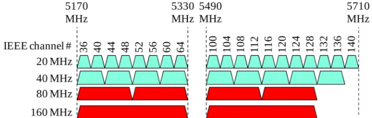
R3.1.A: The draft specification shall include support for 80 MHz PHY transmission.
80 MHz channels consists of two adjacent IEEE 40 MHz channels, and do not partially overlap with each other. 160 MHz channels consists of two adjacent IEEE 80 MHz channels, and do not partially overlap with each other. 80 MHz and 160 MHz channels for the US region are shown in Figure 12.
Figure 12--80 MHz and 160 MHz channels for the US region
[10/773r0][10/1064r2]
Figure 34--80 MHz and 160 MHz channelization for the Europe, Japan and Global operating class tables
[10/1064r2]
R3.1.B: The draft specification shall include support for 160 MHz PHY transmission. [10/0378r1]
R3.1.C: Tone allocation for 160 MHz operation shall consist of two 80 MHz tone allocations. [10/0378r1] R3.1.D: The draft specification shall include support for non-contiguous 160 MHz PHY transmission whose frequency spectrum consists two segments, each transmitted using any two 11ac 80 MHz channels, possibly non-adjacent in frequency. Contiguous and non-contiguous 160 MHz devices shall be capable of transmitting and receiving frames between each other when the two segments of the non-contiguous 160 MHz device are placed in frequency to match the tone allocation of the contiguous 160 MHz device. [10/0378r1]
A VHT STA shall be capable of transmitting and receiving frames using 20 MHz, 40 MHz, and 80 MHz channel width. Contiguous and non-contiguous 160 MHz channel width transmission and reception capability is optional. [10/0827r1]
The primary and the secondary subchannels of the 80 MHz channel to be allocated within a 40 MHz channel. [10/763r0]
R3.1.E: The draft specification shall include support for an efficient channelization in China’s (5,725 ~ 5,850 MHz) spectrum. [10/1062r2]
A noncontiguous 160 MHz BSS shall be setup using any two nonadjacent 80 MHz channels on which a STA is permitted to establish an 80 MHz BSS. [10/1062r2]
3.2 VHT PLCP sublayer
3.2.1 Introduction
A VHT mixed format (MF) preamble shall be supported in the draft specification and device support is mandatory. The VHT mixed format preamble shall have the following characteristics:
R3.2.1.A: Robust legacy 11a deferral. The VHT MF preamble shall be designed such that a legacy 11a device will defer for the duration of the transmission to the same degree that it does for an HT MF preamble.
R3.2.1.B: Robust legacy 11n deferral. A VHT MF preamble shall be designed such that a legacy HT STA will defer for the duration of the transmission to the same degree that it does for an HT MF transmission.
R3.2.1.D: The VHT MF preamble shall include training for
a wider channel
1 to 8 spatial streams (see Section 3.4)
DL MU-MIMO
R3.2.1.E: Since the HT SIG field cannot be expanded without breaking backward compatibility, the VHT MF preamble shall include VHT SIG fields. The VHT SIG fields may include signaling for the following:
a) wider bandwidth
b) enhanced MCS (see Section 3.3) c) more spatial streams (see Section 3.4)
3.2.2 VHT PPDU format
R3.2.1.F: The VHT MF PPDU format is shown in Figure 56.
Figure 56 – VHT PPDU format
The VHT MF PPDU includes a 2 symbol VHT-SIG-A field and a 1 symbol VHT-SIG-B field.
3.2.3 VHT preamble
The number of subcarriers and subcarrier positions of STF are the same as those of the 20 MHz 11n L-STF in each 20 MHz subchannel. [10/0578r1]
The number of subcarriers and pilots, including subcarrier positions, of L-LTF, L-SIG, and VHT-SIG-A are the same as those for the 20 MHz 11n L-LTF and L-SIG in each 20 MHz subchannel. [10/0578r1] The number of subcarriers and pilots, including subcarrier positions, of VHT-LTF and VHT-DATA symbols in 20 and 40 MHz channels are the same as those for 11n HT-LTF and HT-DATA in 20 and 40 MHz channels. [10/0578r1]
The L-STF, L-LTF, L-SIG, VHT-STF and VHT-LTF portions of preamble for 160 MHz VHT
transmissions shall be constructed by repeating the 80 MHz counterparts twice in frequency, once in the lower 80 MHz subchannel and one more time in the upper 80 MHz subchannel of the 160 MHz
bandwidth. [10/0774r0]
In all elements of an 80 MHz VHT PPDU , i.e., the L-STF, L-LTF, L-SIG, VHT-SIG-A, VHT-LTFs, VHT-SIG-B and the Data, subcarrier k, where -122 <= k <= 122, shall be multiplied by the following function of k:
1
,
64
1 ,
64.
k
k
k
�
�
�
[10/1083r0]
3.2.3.1 Non-VHT portion of VHT mixed format preamble
3.2.3.1.1 Cyclic shift definition
The CSD (Cyclic Shift Diversity) values for up to 4 antennas in L-STF, L-LTF, and L-SIG are the same as the CSD values for the non-HT portion of the packet defined in Table 20-8 of Std 802.11n-2009.
[10/0578r1] Note--This requirement is captured in the table below.
The cyclic shift value iTX
CS
T
for the L-STF, L-LTF, L-SIG and VHT-SIG-A portions of the packet for transmitter iTX out of total NTX are defined in the following table.Table 12-- Cyclic shift values for L-STF, L-LTF, L-SIG and VHT-SIG-A portions of the packet TX
i CS
T
values for L-STF, L-LTF, L-SIG and VHT-SIG-A portions of the packet Totalnumber of transmit antennas
(NTX)
Cyclic shift for transmit antenna iTX (in units of ns)
1 2 3 4 5 6 7 8
1 0 - - -
-2 0 -200 - - -
-3 0 -100 -200 - - - -
-4 0 -50 -100 -150 - - -
-5 0 -175 -25 -50 -75 - -
-6 0 -200 -25 -150 -175 -125 -
-7 0 -200 -150 -25 -175 -75 -50
-8 0 -175 -150 -1250 -25 -100 -50 -200 [10/1301r0]
3.2.3.1.2 L-STF definition
The 20 MHz L-STF pattern in the VHT preamble is as defined in 20.3.9.3.3 of Std 802.11n-2009. [10/0578r1]
The L-STF pattern for 160 MHz VHT transmissions shall repeat the 80 MHz L-STF pattern twice in frequency. This corresponds to repeating the 11n 20 MHz L-STF pattern in Equation (20-8) in each of the 20 MHz subchannel, then applying the following phase rotation per 20 MHz subchannel starting from the lowest 20 MHz subchannel in frequency: [c80 c80], where c80 is the phase rotation per 20 MHz
subchannel for 80 MHz transmissions. [10/0774r0]
3.2.3.1.3 L-LTF definition
The 20 MHz L-LTF pattern in the VHT preamble is as defined in 20.3.9.3.4 of Std 802.11n-2009. [10/0578r1]
the lowest 20 MHz subchannel in frequency: [c80 c80], where c80 is the phase rotation per 20 MHz subchannel for 80 MHz transmissions. [10/0774r0]
3.2.3.1.4 L-SIG definition
The L-SIG symbol is BPSK modulated.
The RATE field shall be set to indicate 6 Mbps.
The LENGTH field shall be set to indicate the duration of the packet.
L-SIG for 160 MHz VHT transmissions shall be constructed by repeating the L-SIG for 80 MHz VHT transmissions twice in frequency, once in the lower 80 MHz subchannel and one more time in the upper 80 MHz subchannel of the 160 MHz bandwidth. The following phase rotation per 20 MHz subchannel shall be applied starting from the lowest 20 MHz subchannel in frequency: [c80 c80], where c80 is the phase rotation per 20 MHz subchannel for 80 MHz transmissions. [10/0774r0]
3.2.3.2 VHT portion of VHT mixed format preamble
3.2.3.2.1 Cyclic shift definition
The CSD (Cyclic Shift Diversity) values for up to 4 antennas in VHT-SIG-A are the same as the CSD values for the non-HT portion of the packet defined in Table 20-8 of Std 802.11n-2009. [10/0578r1] The CSD (Cyclic Shift Diversity) table for the VHT portion (starting from VHT-STF) of the SU MIMO frame shall be as follows:
CSD
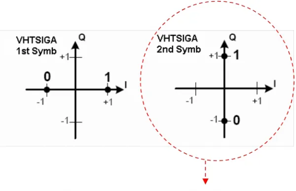
R3.2.1.G: The 1st symbol of VHT-SIG-A shall be BPSK modulated. The second symbol of VHT-SIG-A
Figure 78 - VHT-SIG-A modulation R3.2.1.H: VHT-SIG-A includes the fields listed in Table 34.
Table 34 - VHT-SIG-A fields Bit
Index
Field Bit allocationDescription
VHT-SIG-A1
0-1 BW 2 Set to 0 for 20 MHz, 1 for 40 MHz, 2 for 80 MHz, 3 for 160 MHz and 80+80 MHz mode
2 Reserved 1 Reserved for possible expansion of BW field. Set to 1.
3 STBC 1 Set to 1 if all streams use STBC, otherwise set to 0. When STBC bit is 1, an odd number of space time streams per user is not allowed.
4-9 Group ID [10/0582r1]
6 A value of all ones indicates [10/0382r2]: - A single user transmission
- A transmission where the group membership has not yet been established
- A transmission that needs to bypass a group (e.g. broadcast)
10-21 NSTS
[10/0582r1]
12 For MU: 3 bits/user with maximum of 4 users
• Set to 0 for 0 space time streams
• Set to 1 for 1 space time stream
• Set to 2 for 2 space time streams
• Set to 3 for 3 space time streams
• Set to 4 for 4 space time streams
22 No TXOP PS 1 Set to 1 to indicate that TXOP PS is not allowed Set to 0 to indicate that TXOP PS is allowed
Set to the same value in all PPDUs in downlink MU TXOP [11/0090r0]
22-23 Reserved 12 All ones Set to 1
Total 24
VHT-SIG-A2
0-1
Short GI
2
Set B0 to 0 for Long GI, set to 1 for Short GI
Set B1 to 1 when Short GI and N
sym%10 == 9
2-3
Coding
2
For SU:
Set B2 to 0 for BCC, set to 1 for LDPC
For MU: [10/1277r0]
Set B2 to 0 for BCC, set to 1 for LDPC for 1
stuser
If user 1 has 0 Nsts value, then B2 is reserved and
set to 1
B3 is defined as N
ldpc-ext(see 3.2.4.2.2)
4-7
MCS
4
For SU/Broadcast/Multicast: MCS index
For MU: [10/1277r0]
B4: Set to 0 for BCC, 1 for LDPC for the 2nd user B5: Set to 0 for BCC, 1 for LDPC for the 3rd user B6: Set to 0 for BCC, 1 for LDPC for the 4th user If user 2, 3, or 4 has 0 Nsts value, then corresponding bit is reserved and set to 1
B7: Reserved and set to 1
8
SU-Beamformed
1
Set to 1 when packet is a SU-beamformed packet
Set to 0 otherwise
For MU: Reserved, set to 1
9
Reserved
1
All ones
10-17
CRC
8
CRC calculated as in 11n Section 20.3.9.4.4 with C7 in B10
18-23
Tail
6
All zeros
Total
24
Note that the fields are transmitted in the order shown in and LSB first. [10/1052r0]
A Smoothing bit shall not be included in either VHT-SIG-A or VHT-SIG-B. [10/0382r2]
3.2.3.2.3 VHT-STF definition
The frequency domain sequence used to construct the VHT-STF in 20 MHz transmission is identical to the L-STF; in 40 MHz transmission, the VHT-STF is constructed from the 20 MHz version by
duplicating, frequency shifting, and rotating the upper sub-carriers by 90°; in 80 MHz transmission, the VHT-STF is constructed from the 20 MHz version by replicating it in each 20 MHz band, frequency shifting, and applying appropriate phase rotations for each 20MHz sub-band. [10/843r0]
For a 160 MHz transmission, subcarriers in the VHT-STF symbol with indices -250 to -6 shall use the VHT-STF pattern for the 80 MHz VHT-STF, with the VHT-STF pattern for subcarrier index -122 mapping to subcarrier index -250 in the 160 MHz transmission. Furthermore, subcarriers in the VHT-STF symbol in the 160 MHz transmission with indices 6 to 250 shall also use the the VHT-VHT-STF pattern for the 80 MHz VHT-STF, with the VHT-STF pattern for subcarrier index -122 mapping to subcarrier index 6 in the 160 MHz transmission. All other subcarriers shall not be modulated. [10/843r0] For non-contiguous transmissions using two 80 MHz frequency segments, each 80 MHz frequency segment shall use the VHT-STF pattern for the 80 MHz VHT-STF. [10/843r0]
VHT-STF sequence for 160 MHz VHT transmissions shall be constructed by repeating the VHT-STF sequence for 80 MHz VHT transmissions twice in frequency as follows
250,250 122,122
, 0, 0, 0, 0, 0, 0, 0, 0, 0, 0, 0,
122,122VHTSTF
VHTSTF
VHTSTF
where VHTSTF-122,122 is the VHT-STF sequence for 80 MHz VHT transmissions. The following phase rotation per 20 MHz subchannel shall be applied starting from the lowest 20 MHz subchannel in
frequency: [c80 c80], where c80 is the phase rotation per 20 MHz subchannel for 80 MHz transmissions. [10/774r0]
3.2.3.2.4 VHT-LTF definition
The long training fields consists of one, two, four, six or eight VHT long training fields (VHT-LTFs) that are necessary for demodulation of the VHT-Data portion of the PPDU or for channel estimation during an NDP packet. [10/0566r2]
The VHT-LTF mapping matrix P for one, two or four VHT-LTFs shall be the same as defined in 802.11n standard specification (Section 20.3.9.4.6, Eq. (20-27)). [10/0566r2]
The VHT-LTF mapping matrix P for six VHT-LTFs is defined as follows:
1 2 3 4 5
where P4x4 is defined by Equation 20-27 in Std 802.11n-2009. [10/0566r2]
The VHT-LTF symbols shall have the same number of pilot subcarriers as the data symbols. The pilot subcarrier indices of the VHT-LTF symbols shall be identical to the pilot subcarrier indices of the data symbols. The pilot values on these subcarrier indices during VHT-LTFs shall be given by the elements at the corresponding indices of the VHT-LTF sequence.
The VHT-LTF mapping matrix P shall be applied to all subcarriers in the VHT-LTF symbols except for the pilot subcarriers. Instead, a row-repetition matrix R shall be applied to all pilot subcarriers in the VHT-LTF symbols. The row-repetition matrix R has the same dimensions as the matrix P (NSTS x NLTF),
with all rows of the matrix R being identical to the first row of the matrix P of the corresponding
dimension. This results in all space-time streams of the pilot subcarriers in VHT-LTF symbols having the same pilot values.
For each pilot subcarrier, the same per-stream CSD and spatial mapping shall be applied across VHT-LTF and data symbols. [10/0771r0]
In a 80 MHz transmission, the VHT-LTF sequence to be transmitted (on subcarriers -122 to 122) shall be:
The VHT-LTF sequence for 160 MHz VHT transmissions shall be constructed by repeating the VHT-LTF sequence for 80 MHz VHT transmissions twice in frequency as follows
250,250 122,122
, 0, 0, 0, 0, 0, 0, 0, 0, 0, 0, 0,
122,122VHTLTF
VHTLTF
VHTLTF
where VHTLTF-122,122 is the VHT-LTF sequence for 80 MHz VHT transmissions. The following phase rotation per 20 MHz subchannel shall be applied starting from the lowest 20 MHz subchannel in
frequency: [c80 c80], where c80 is the phase rotation per 20 MHz subchannel for 80 MHz transmissions. [10/0774r0]
3.2.3.2.5 VHT-SIG-B definition
VHT-SIG-B shall be BPSK modulated. VHT-SIG-B shall use long GI.
Figure 910 - VHT-SIG-B in 20, 40 and 80 MHz transmissions
In a 160 MHz PPDU, the 80 MHz VHT-SIG-B is repeated twice in frequency.
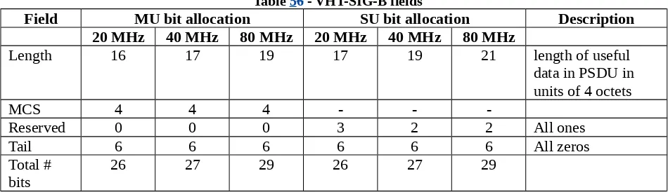
R3.2.1.I: VHT-SIG-B includes the fields listed in Table 56
Table 56 - VHT-SIG-B fields
Field MU bit allocation SU bit allocation Description 20 MHz 40 MHz 80 MHz 20 MHz 40 MHz 80 MHz
Length 16 17 19 17 19 21 length of useful data in PSDU in units of 4 octets
MCS 4 4 4 - -
-Reserved 0 0 0 3 2 2 All ones
Tail 6 6 6 6 6 6 All zeros
Total # bits
26 27 29 26 27 29
NOTE –varying the Length field size with channel width and SU/MU ensures that a consistant packet duration of approximately 5.4ms (the max packet duration from L-SIG) is maintained.
Order of transmission: Length, MCS (in case of MU) / Reserved (in case of SU), Tail. Fields are transmitted LSB first. [10/1052r0]
The number of octets implied by VHT-SIG-B length shall not be more than 3 octets longer than the number of octets implied by L-SIG LENGTH and VHT MCS.
For VHT NDP, fixed bit patterns are defined for VHT-SIG-B in the 20, 21, and 23 useful VHT-SIG-B bits for 20, 40, and 80 MHz, respectively. These bit patterns are shown to have the lowest Peak-to-Average Power Ratio (PAPR) when using a four times oversampled IFFT.
The following sequences (showed LSB first) shall be used for VHT-SIG-B in VHT NDPs: 20 MHz: 0 0 0 0 0 1 1 1 0 1 0 0 0 1 0 0 0 0 1 0 (PAPR = 3.16 dB)
40 MHz: 1 0 1 0 0 1 0 1 1 0 1 0 0 0 1 0 0 0 0 1 1 (PAPR = 5.42 dB) 80 MHz: 0 1 0 1 0 0 1 1 0 0 1 0 1 1 1 1 1 1 1 0 0 1 0 (PAPR = 5.13 dB) [10/1290r0]
3.2.4 VHT Data field
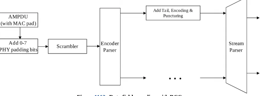
The number of OFDM symbols in the Data field shall be computed using the length field in L-SIG. For both BCC and LDPC, all bits (including MAC and PHY pad bits) shall be encoded.
used, the Data field shall consist of the 16-bit SERVICE field, the PSDU and the PHY pad bits. No tails bits are included when LDPC encoding is used.
Figure 1112--Data field encoding with BCC
For BCC encoding, the interleaver parameters for 20 MHz and 40 MHz 802.11ac packets will remain unchanged from 20 MHz and 40MHz 802.11n, i.e. the NCOL and NROT parameters for 20/40MHz are as in
Table 20-16 from 802.11n-2009. [10/548r2]
For a SU transmission using BCC encoding, the padding flow is as follows. The MAC calculates the NSYM
and NPAD using the following equations:
The MAC then pads to the last byte boundary and indicates (using the TXVECTOR) the number of PHY pad bits to the added. After receiveing the PSDU, the PHY adds the 0-7 padding bits and then NES tail bits at each encoder. [10/820r0]
For an MU transmission using BCC encoding, the padding flow is as follows. The MAC calculates NSYM
for each user separately using the following equations:
(1) (2) (K)
max
max(
SYM,
SYM,. ...
SYM)
SYM STBC
STBC
N
N
N
N
m
m
�
�
�
�
�
�
( )k max ( )k
8
( )K ( )kPAD SYM DBPS service tail ES
N
N
N
L
N
N N
For each user, based on the maximum number of symbols over all users, the MAC pads to the last byte boundary. The number of PHY padding bits added for each user is calculated as in the SU case. For each user, the encoding and stream parsing is done as in the SU case. [10/820r0]
3.2.4.1 SERVICE field
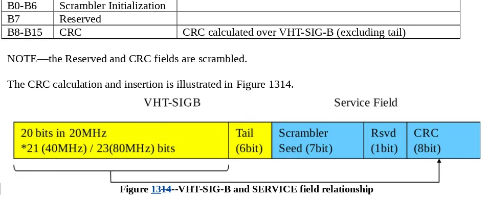
The SERVICE field is as shown in Table 3.
Table 78 - SERVICE field
B0-B6 Scrambler Initialization B7 Reserved
B8-B15 CRC CRC calculated over VHT-SIG-B (excluding tail) NOTE—the Reserved and CRC fields are scrambled.
The CRC calculation and insertion is illustrated in Figure 1314.
Figure 1314--VHT-SIG-B and SERVICE field relationship
The CRC is calculated over the VHT-SIG-B bits, excluding the tail bits using the CRC defined in
802.11n-2009 section 20.3.9.4.4. C7 of the CRC is mapped to B8 of the SERVICE field, C6 to B7, …, C0 to B15.
The resulting SERVICE field and PSDU shall be scrambled, as in 11n.
3.2.4.2 Coding
3.2.4.2.1 BCC coding
The draft specification shall support the following:
The maximum data rate per BCC encoder is 600Mbps
The number of BCC encoders for a particular combination of MCS, Nsts and BW is determined by the short GI data rate and the same number of encoders are used for the corresponding normal GI rate
The number of BCC encoders is not limited
3.2.4.2.2 LDPC coding
The draft specification shall include the same LDPC PPDU encoding process from 802.11n (described in Section 20.3.11.6.5) for 11ac, regarding codeword length, shortening, puncturing and repetition.
[10/1300r0]
The procedure for encoding and decoding the payload for an SU packet is as follows. Number of initial payload OFDM symbols:
sym_init STBC
Number of final payload OFDM symbols:
sym sym_init STBC ldpc_ext
ldpc_ext
For LDPC:
,
where
is a one bit flag indicating if LDPC PPDU will spill into
extra OFDM symbol/symbols
N
N
m
N
N
ldpc-ext
N
flag is hosted in VHT-SIGA2.B3At the receive side, the number of payload OFDM symbols:
LTF
The procedure for encoding and decoding a MU packet is as follows:
For each user in the MU packet, compute the initial number of OFDM symbols
N
sym_init,u:ES,
Finds the initial estimate of the longest symbol length:
USERS 1For each LDPC users, go through LDPC PPDU math to find if extra OFDM symbol (or symbols) are needed:
If at least one of the LDPC users require extra OFDM symbol (or symbols), set
N
ldpc-ext
1
(VHT-SIGA2.B3 = 1).
Otherwise, set
N
ldpc-ext
0
(VHT-SIGA2.B3 = 0).L-SIG length is set based on the actual length of the packet:
sym sym_max_init STBC ldpc_ext
N
N
m
�
N
For each user, construct PSDU by:
For LDPC users, add sufficient MAC padding to fill up
N
sym_max_initsymbols For BCC users, add sufficient MAC padding to fill upN
symsymbolsFor each LDPC user in the MU packet, encode the PSDU using LDPC PPDU process
If
N
ldpc-ext
1
, LDPC PPDU encoding process addsm
STBC symbols IfN
ldpc-ext
0
, LDPC PPDU encoding does not add extra symbolsFor each BCC user, encode the PSDU using BCC encoder. Note that the tail bits are placed at the very end of the packet.
3.2.4.3 Data interleaver
3.2.4.3.1 Stream parser
For BCC encoding, stream parsing done in the same way as 11n, i.e.,
- Consecutive blocks of s(iss) bits are assigned to different spatial streams in a round robin fashion.
- If multiple encoders are present per user, the output of each encoder is used in a round robin cycle, i.e.,
o At the beginning S bits from the output of first encoder are fed into all spatial streams,
o Then S bits from the output of the next encoder are used and so on. S is a sum of s(iss)
over all streams)
In case of contiguous and noncontiguous 160 MHz transmissions, even output bits of the stream parser are allocated to the lower 80 MHz and odd output bits to the upper 80 MHz for each stream. First output bit from the stream parser in each symbol is an even bit.
For 160MHz, if each BCC encoder does not generate integer blocks of S coded bits in each OFDM symbol, then apply the same stream parsing method until the last integer block (floor(NCBPS/NES/S)) of S
bits at each encoder.
Assuming that at this point in each OFDM symbol each BCC has M.s (M<NSS) residue bits, take the last
M.s bits in the current OFDM symbol from the first encoder and allocate them to the first M spatial streams (s bits to each stream); then take the last M.s bits in the current OFDM symbol from the second encoder and distribute these among M spatial streams, starting from the (M + 1)-th spatial stream, and so on. Note that upon reaching the NSS’th spatial stream, we cycle back to the 1st spatial stream. Repeat till
all bits are distributed in the current OFDM symbol. [10/1264r1]
3.2.4.3.2 Segment Parser
In case of contiguous 160 MHz or non-contiguous 80+80 MHz VHT PPDU transmissions, the output bits of each stream parser are first divided into blocks of
N
CBPSS bits. Then, each block is further divided into two subblocks ofN
CBPSS2
bits as shown in the equation below:where
z
��
��
is the largest integer less than or equal toz
modz t is the remainder resulting from the division of integer
z
by integer tm
If
N
CBPSS is not divisible by2
s N
�
ES, then apply the segment parsing method described in the equation above, for ��NCBPSS
2s N�ES
�� blocks of2
s N
�
ES segment parser input bits. At this point, each streamparser output has 2s R�
R N
ES, integer
residue bits. Then, the residue bits are divided into blocksof
s
bits, with each block being assigned to different subblock (l
0,1
) in a round robin fashion. The firsts
bits are assigned to the subblock with index l0. Repeat R times until all bits are distributed to the two subblocks.Segment parser is bypassed in case of 20, 40 and 80 MHz VHT PPDU transmissions. [10/1279r0]
3.2.4.3.3 Frequency interleaver
For BCC encoding, the interleaver parameters for 20 MHz and 40 MHz 802.11ac packets will remain unchanged from 20 MHz and 40 MHz 802.11n, i.e. the NCOL and NROT parameters for 20 MHz and 40
MHz are as in Table 20-16 of 802.11n-2009. [10/548r2]
For BCC encoding, NCOL = 26 for 80 MHz. NROT = 58 for 4 or fewer streams. The cyclic shifts applied on
the different streams are given by [0 2 1 3]* NROT, identical to 11n
For BCC encoding, the encoder parsing done in the same way as in 11n, i.e., the encoder parser cycles through all the encoders in a round robin fashion assigning one bit to each encoder in each cycle. Each encoder is therefore assigned an equal number of bits.
For contiguous and noncontiguous 160 MHz transmissions using BCC encoding, the lower and upper 80 MHz portions are each interleaved using the interleaver defined for 80 MHz transmissions.
For BCC encoding, when Nss>4, the third permutation of the interleaver uses the following parameters:
Permutation as the first Nss values of [0 5 2 7 3 6 1 4]*NROT *NBPSCS. NROT =28, 13 and 6 for 80MHz, 40MHz and 20MHz, respectively.
[11/0048r0]
3.2.4.4 Constellation mapping
Figure 1516--Constellation mapping for 256 QAM
The normalization factor, KMOD, for 256 QAM is
1/ 170
. [10/1090r0]3.2.4.5 LDPC tone mapping
Define DTM to be the tone mapping distance, which takes values in Table 4 for various bandwidths.
Table 910--LDPC tone mapping distance for various bandwidths Parameter 20 MHz 40 MHz 80 MHz (2 x 80 MHz)160 MHz
DTM 4 6 9 9
After constellation mapping, for user u we have the complex numbers.
, ,
,
0,1, ,
SD1,
1, ,
SS,,
0,1, ,
SYM1
k l n u
d
k
K
N
l
K
N
n
K
N
If LDPC encoding is used, the LDPC tone mapper permutes the stream of constellation numbers to obtain
, , ( ), ,
k l n t k l n
d
�
d
.
( )
.( mod
SD)
TMTM
TM SD
N
k D
t k
D
k
D
N
�
�
�
�
�
�
This operation is equivalent to block-interleaving the constellation symbols per stream, per OFDM symbol, using a matrix with DTM rows and NSD /DTM columns, by writing
d
k l n, , row-wise, and readingback
d
k l n�
, , column-wise.For 160 MHz, the LDPC tone mapping for LDPC-coded streams is performed separately for the upper and lower 80 MHz frequency segments.
[10/1300r0]
3.2.4.6 Pilot subcarriers
The draft specification shall have 8 pilot tones, with the positions {±103, ±75, ±39, ±11}, for 80 MHz VHT data. [10/0370r1]
For 20 and 40 MHz, the pilot sequence shall be the single spatial stream pilot sequence of 11n copied to the NSTS streams before the per-stream CSDs are applied. [10/0811r1]
For 80 MHz, the pilot sequence shall be as defined in Table 1112 (which is the 40 MHz pilot sequence for NSTS = 1 extended with a [1, 1] on the right, resulting in the lowest PAPR on the pilot tones after applying
[1 -1 -1 -1] rotation on the 20 MHz subbands), copied to the NSTS streams before the per-stream CSDs are
applied. [10/0811r1]
Table 1112--80 MHz pilot sequence
3.2.4.6.1 Application of pilot sequence in 20 MHz
The pilot tone mapping in 20 MHz shall be:
1 1 1 1
{ 21, 7,7,21}
1, mod 4
,
1,( 1)mod 4,
1,( 2)mod 4,
1,( 3)mod 4n n n n n
P
where
1, 1m is given by the NSTS = 1 row of Table 20-18 of Std 802.11n-2009, and where n is theVHT-DATA symbol index starting at 0.
Including the pseudo random scrambling sequence, the pilot value for the kth tone, with k = {-21, -7, 7, 21}, is pn+zPnk, where z = 4 for VHT, and where pn is defined in Section 17.3.5.9 of IEEE802.11.
3.2.4.6.2 Application of pilot sequence in 40 MHz
DATA symbol index starting at 0.
Including the pseudo random scrambling sequence, the pilot value for the kth tone, with k = {-53, -25, -11, 11, 25, 53}, is pn+zPnk, where z = 4 for VHT, and where pn is defined in Section 17.3.5.9 of
IEEE802.11. This does not include the rotation per 20 MHz subband yet.
3.2.4.6.3 Application of pilot sequence in 80 MHz
The pilot tone mapping in 80 MHz shall be:
{ 103, 75, 39, 11,11,39,75,103}
mod8 ( 1)mod8 ( 2)mod8 ( 3)mod8
Including the pseudo random scrambling sequence, the pilot value for the kth tone, with k = {-103, -75, -39, -11, 11, 39, 75, 103}, is pn+zPnk, where z = 4 for VHT, and where pn is defined in Section 17.3.5.9 of
IEEE802.11. This does not include the rotation per 20 MHz subband yet.
3.2.4.6.4 Application of pilot sequence in 160 MHz
The draft specification shall have 16 pilot subcarriers, with the subcarrier indices {±25, ±53, ±89, ±117, ±139, ±167, ±203}, for 160 MHz VHT transmissions. The pilot sequence and mapping for 160 MHz VHT transmissions shall be obtained by repeating the 80 MHz pilot sequence and mapping twice in frequency. Specifically, the pilot sequence for the nth symbol shall be as follows, where Ψn is the 80
MHz pilot pattern:
231, 203, 167, 139, 117, 89 53, 25,25,53,89,117,139,167,203,231
mod 8 1 mod 8 2 mod 8 3 mod 8 4 mod 8 5 mod 8 6 mod 8 7 mod 8
Including the pseudo random scrambling sequence, the pilot value for the kth tone, with k = {±25, ±53, ±89, ±117, ±139, ±167, ±203}, is pn+zPnk, where z = 4 for VHT, and pn is defined in Section 17.3.5.9 of
IEEE802.11-2007. Note that this does not include the phase rotation per 20 MHz subchannel yet. [10/0774r0]
3.2.4.7 OFDM modulation
The draft specification shall have 3 DC tones at (0, ±1) in the 80 MHz VHT data field. [10/0370r1] The draft specification shall have 5 null tones at the upper tone edges (tone indices 123, 124, 125, 126, 127) and 6 null tones at the lower tone edges (tone indices -128, -127, -126, -125, -124, -123) of the 80 MHz VHT data. [10/0370r1]
subchannel in frequency: [c80 c80], where c80 is the phase rotation per 20 MHz subchannel for 80 MHz transmissions. [10/0774r0]
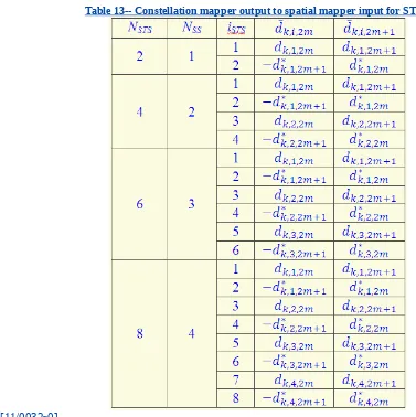
3.2.4.8 Space-time block coding
When all streams use STBC, an odd number of space time streams per user shall not be used, and NSTS=2*NSS. For NSTS=2,4, the constellation mapper output to the spatial mapper input for STBC table
shall reuse mapping as defined in Clause 20.3.11.8.1. For NSTS=6,8, the constellation mapper output to the
spatial mapper input shall follow the mapping as defined in Table 7, similarly to mapping defined for NSTS=2,4.
Table 13-- Constellation mapper output to spatial mapper input for STBC
[11/0032r0]
3.2.5 VHT Sounding PPDU
R3.2.5.A: The sounding PPDU shall be enhanced from the HT sounding PPDU to support a maximum of 8 transmit antennas.
R3.2.5.B: The draft specification shall mandate a single preamble format for sounding PPDUs. NDP shall be the only VHT sounding format. [10/1105r0]
The VHT NDP format is shown in Figure 1718 and has the following properties: - it has the same the VHT PPDU format but with no data portion
- and has VHT-SIG-B carrying a TBD fixed bit pattern
Figure 1718--VHT NDP format
3.3 Modulation and coding scheme (MCS)
R3.3.A: The draft specification shall include 256 QAM. Support for 256 QAM by a VHT STA is optional. [10/0827r1]
R3.3.B: The draft specification shall maintain the 11n modulation, interleaving and coding architecture.
R3.3.C: The draft specification shall minimize the number of additional MCS options.
R3.3.D: The draft specification shall include support for a different MCS for each STA in a DL MU-MIMO transmission.
R3.3.E: The draft specification shall include an expanded MCS set for the additional spatial streams supported.
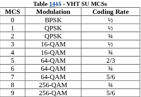
R3.3.F: The SU MCSs are shown in Table 1415. MCS 9 shall not be used in 20 MHz BW transmissions. [10/0568r1]
For BCC encoding, some of the MCS-NSS combinations are excluded from the MCS table to avoid
additional padding symbols. Allowed MCSs are selected such that the number of coded bits in each OFDM symbol contains an integer number of punctured blocks from all encoders, i.e., mathematically every allowed MCS-NSS satisfies:
The same MCS table shall be used for both BCC and LDPC coded transmissions. [10/1300r0]
3.4 Spatial Multiplexing
R3.4.A: The maximum number of spatial streams (NSTS) in a SU transmission shall be 8.
R3.4.B: The maximum number of streams (NSTS) summed over all users in a MU transmission shall be 8.
R3.4.C: The maximum number of streams (NSTS) for a single user in a MU transmission shall be 4.
R3.4.D: The same modulation and the same coding rate and coding type shall be used on all streams in a SU transmission.
R3.4.E: The same modulation and the same coding rate and coding type shall be used across all streams belonging to each user in a MU transmission. [10/0382r2]
3.5 CCA
R3.5.A: CCA shall support detection and deferral on the 20 MHz subchannels that are busy for any possible combination of channel use and signalling bandwidth with a single transmission in an otherwise idle RF bandwidth. This includes
a) a single 20 MHz transmission on any 20 MHz sub-channel b) a single 40 MHz transmission on either 40 MHz sub-channel c) a single 80 MHz transmission
R3.5.B: An 11ac device shall provide a CCA per TBD1 MHz channel, for all TBD1 MHz non-overlapping channels that the device is presently capable of
transmitting over. The CCA sensitivity shall be:
TBD2 (<-62+10log10(TBD1/20)) dBm for valid 802.11 signals
-62+10log10(TBD1/20) dBm for any signal. [10/744r1]
The CCA levels for secondary channels shall be 20MHz: - 72 dBm
40MHz: - 72 dBm 80MHz : - 69 dBm [11/0061r0]
3.6 PMD transmit specification
3.6.1 Transmit center frequency
Carrier (LO) and symbol clock frequencies for all transmit chains and frequency segments shall be derived from the same reference oscillator.
Phase of carrier frequency shall not be required to be correlated between the lower and upper 80 MHz frequency portions of the transmitted signal for 160 MHz PPDUs.
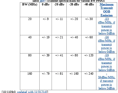
The transmit spectral mask for 20 MHz, 40 MHz, 80 MHz and 160 MHz PPDUs is shown in Table 86.
Table 1617--Transmit spectral mask for various BW PPDUs BW (MHz) 0 dBr -20 dBr -28 dBr -40 dBr Maximum
[10/1109r0, updated with 11/0121r0]
The transmit mask for non-contiguous 160 MHz PPDUs shall be constructed as follows: Place two 80 MHz TX masks, one for each segment
v1 = Mask value of one 80 MHz mask v2 = Mask value of the other 80 MHz mask
For frequencies where (-40 dBr < v1 < -20 dBr) and (-40 dBr < v2 < -20 dBr) Mask value = v1 + v2 (sum in linear domain)
For frequencies where NOT {(-20 dBr < v1 < 0 dBr) or (-20 dBr < v2 < 0 dBr)} Mask value = max(v1, v2)
For all other frequencies
Mask value = linearly interpolate (in dB domain) [10/1255r1]
3.6.3 Spectral flatness
The average energy in the subcarriers of a PPDU shall deviate by no more than that shown in Table 1819.
Table 1819--Average energy variation on subcarriers
Note: A noncontiguous 160 MHz devices may transmit a contiguous 160 MHz waveform by placing its two 80 MHz segments adjacent to each other. It would be difficult for such transmissions to meet the +4/-4 dB requirement near the center of the contiguous 160 MHz waveform.
[10/1109r0]
3.6.4 Modulation accuracy
3.6.4.1 Transmit constellation error
The transmit EVM requirements for 256-QAM ¾ and 256-QAM 5/6 shall be -30 dB and -32 dB respectively. The Tx EVM requirements for other MCSs are as in 11n. [11/0029r0]
3.7 PMD receiver specification
3.7.1 Receiver minimum input sensitivity
The receiver minimum input sensitivity shall be as shown in Table 10.
Table 20--Receiver minimum input sensitivity
Modulation Rat
The adjacent/non-adjacent channel test is defined as follows:
Desired signal strength = 3 dB above RX sensitivity
If desired signal BW = 20/40/80/160 MHz
o Interfering signal (same BW as the desired signal) placed W MHz away from the center frequency of the desired signal
Adjacent channel rejection : W = BW of the desired signal
Nonadjacent channel rejection : W ≥ 2 * BW of the desired signal
o An interfering signal of 80 MHz BW placed W MHz away from the center frequency of one of the desired signal frequency segments
Adjacent channel rejection : W = 80 MHz
Nonadjacent channel rejection : W ≥ 160 MHz
Raise power of interfering signal until 10% PER reached
The minimum required adjacent and nonadjacent channel rejection levels shall be as shown in Table 11.
Table 21-- Minimum required adjacent and nonadjacent channel rejection levels
Modulation Rate
The OFDM PHY clause has the scrambler definition modified.
3a.1 PLCP DATA scrambler and descrambler
New paramters INDICATED_DYN_BANDWIDTH and INDICATED_CH_BANDWIDTH are added to the TXVECTOR and RXVECTOR.
The following bits in the scrambling sequence correspond to these parameters: INDICATED_DYN_BANDWIDTH: B4 set to 0 (Static) or 1 (Dynamic)
INDICATED_CH_BANDWIDTH: B5-B6 set to 0 (20 MHz), 1 (40 MHz), 2 (80 MHz), or 3 (160 or 80+80 MHz)
When both INDICATED_DYN_BANDWIDTH and INDICATED_CH_BANDWIDTH are present then the scrambling sequence scramblingSequenceStart4 is randomly chosen from 1-15. When the
INDICATED_CH_BANDIWDTH is present, the scrambling sequence scramblingSequenceStart5 is randomly chosen from 1-31.
This is summarized in the table below:
Bits 0-3 4 5-6
RTS scramblingSequenceStart4 INDICATED_DYN_B ANDWIDTH
INDICATED_CH_BANDWIDTH
CTS etc scramblingSequenceStart5
the First 7 Bits in the Scrambling Sequence (see table above) the Scrambler output given that the initial Scrambler State is set to the First 7 Bits in Scrambling Sequence (see figure below).
Figure 1920--Modified scrambler operation
[10/1281r1]
4 DL MU-MIMO and Transmit Beamforming
R4.A: DL MU-MIMO shall be built on one type of the 11n channel sounding PPDU and transmit beamforming protocol.
R4.B: DL MU-MIMO shall provide MAC protocol extensions to support multiple acknowledgement responses from the individual STAs receiving the MU-MIMO transmission.
R4.C: The DL MU-MIMO MAC protocol extensions shall work with EDCA
A sounding responder shall have the ability to reduce the receive side feedback dimension of its MIMO channel with explicit MU-MIMO feedback. The extent of the reduction is TBD.
[10/1114r1]
Only explicit sounding and feedback shall be supported for VHT SU beamforming and DL MU-MIMO. [10/1105r0]
Compressed V matrix feedback (based on 20.3.12.2.5 and 7.3.1.29 in 11n spec) shall be the only feedback format for SU beamforming and MU-MIMO. [10/1105r1]
The beamformer shall be able to control the explicit feedback dimension for each user in MU-MIMO operation. [10/1265r1]
4.1 Resolvable LTFs for DL MU-MIMO
5 Coexistence
R5.A: Channel access rules shall ensure fair access to the medium for TGac compliant devices and legacy devices operating within a BSS or in seprate overlapping BSSs.
R5.B: The draft specification shall provide a mechanism that ensures that TGac transmissions are protected from legacy channel access for the duration of the transmission.
R5.C: The Primary Channel may be designated to any 20MHz subchannel over 80MHz channel
bandwidth, where Primary Channel designation is subject to co-existence (OBSS) rules yet to be defined. [10/0593r1]
R5.D: non-ht quadruplicate and non-ht octuplicate mode shall be included in the specification: A transmission format of the physical layer (PHY) that duplicates a 20 MHz non-HT transmission in four adjacent 20 MHz channels or two sets of four adjacent 20 MHz channels.
[10/1096r7]
The use of RIFS is deprecated. A VHT STA shall not transmit non-HT, HT or VHT frames separated by RIFS. A VHT AP shall set the RIFS Mode field in the HT Operation element to 0.
[11/0033r1]
5.1 Channel Access
The 802.11n PIFS medium access mechanism is extended to 80MHz and 160MHz operation, as described below:
AIFS deferral and random backoff based on the primary channel activity
All transmissions shall occupy the primary channel and
Secondary channels occupied by the transmission shall be sensed idle PIFS prior to the transmission
[10/1084r0]
If there is no non-HT duplicate frame exchange in a TXOP to set the NAV, then the TXOP holder shall not transmit frames using more bandwidth than the bandwidth occupied by the preceding frame in the same TXOP.
[11/0081r1]
If there is at least one non-HT duplicate frame exchange (not a RTS/CTS exchange) in a TXOP, then the TXOP holder shall not transmit frames using more bandwidth than the bandwidth occupied by the first non-HT duplicate frame exchange in the same TXOP.
[11/0081r1]
5.2 Backoff procedure
Rules in section 9.9.1.5 of 802.11n-2009 can be directly applied to the MU-MIMO acknowledgment frame exchange.
If one of the frames in the MU-PPDU requires an immediate response, a missing or incorrect immediate response indicates a failed MU-PPDU and triggers the backoff procedure.
A MU PPDU is successful if none of the frames require an immediate response or if the required immediate response is correctly received.
[10/1092r0]
If a valid response to the initial frame of a TXOP is not received, the AP shall initiate an exponential backoff for the primary AC. [11/0082r0]
6 MAC
6.1
Power saving
Two mechanism are provided to terminate receive processing early. The receiver may use the length indication in VHT-SIG-B and/or use the EOF indication in the MAC padding.
6.1.1 DL MU TXOP Power Save
A DL MU TXOP Power Save capable STA may operate as follows during a MU TXOP:
STA saves power till the end of DL MU TXOP after it finds that it is not a member of Group ID received in VHT-SIG-A.
STA saves power till the end of DL MU TXOP after receiving VHT-SIG-A with corresponding NSTS = 0 for its position in Group ID.
STA saves power till the end of DL MU TXOP after sending BA in response to frame with “More Data” bit =0.
Note that support for DL MU TXOP power save is optional at both STA and AP
If AP chooses to allow MU TXOP power saving for a downlink MU TXOP, then AP shall include NAV-set sequence at the beginning of that TXOP.
The TXOP power management modes are shown in Figure 2122.
Figure 2122--Power management modes
The draft amendment shall include a bit that indicates whether or not the AP allows STAs in TXOP PS mode to do power save during a downlink MU TXOP. The exact bit to be used is TBD.
DL MU TXOP Power Save is extended for power save during an SU-MIMO TXOP. Change the signals from MU MIMO TXOP Power Save to VHT Power Save.
Editor’s note: The intent of the above statement is to rename the scheme and associated fields to reflect the more general purpose.
STAs can enter doze state:
If the received Partial AID in VHT-SIG-A does not match the partial AID of STA
If the partial AID in VHT-SIG-A matches the partial AID of STA but the frame is not destined to it.
After sending appropriate acknowledgement to AP in response to frame received with ‘More Data’ bit set to 0.
[11/0091r0]
6.2 Capability negotiations
A VHT STA indicates the following capabilities:
Max A-MPDU length supported as exponent n where 0 <= n <=7 and indicates a max A-MPDU length (2^(13+n)-1)B.
Max A-MSDU length supported as 3839B, 7935B or {11454B-Max MAC Header-FCS}. [10/1079r1]
The VHT Capabilities element has the format shown in Figure 2324. [10/1267r1]
Figure 2324--VHT Capabilities element
The VHT Capabilities Info field has an additional field (not shown in Figure 12): Number of Sounding Dimensions. [11/0052r0]
The VHT Capabilities element includes a Max MPDU Length field with the following encoding:
Set to 0 for 3895 octets (Maximum A-MSDU Lenth in HT Capabilities set to 3839 octets)
Set to 1 for 7991 octets (Maximum A-MSDU Length in HT Capabilities set to 7935 octets) LDPC Coding
Capabilities
Supported Channel Width Set
Short GI for
20/40/80/160 STBCTx STBCRX MPSDU Len.Max A- Tx MU MIMO Rx MU MIMO Other fields
Bits: 1 2 (TBD) 1 (TBD) 2 (TBD) (TBD) (TBD)
Support at least 2x1 STBC 00: No support for
160MHz and 80+80MHz 01: Support 160MHz
10: Support 160MHz and 80+80MHz 11: reserved
x: 0-7 => 2(13+x)-1 B
Element ID Length Capabilities InfoVHT ParametersA-MPDU Supported MCS Set Beamforming Capabilities
Set to 2 for 11454 octets (Maximum A-MSDU Length in HT Capabilities set to 7935 octets)
The value 3 is reserved [11/0034r0]
The VHT Capabilities element includes a MU TXOP Management Mode field (not shown in Figure 12). This field indicates whether or not the AP allows the STAs in BSS to enter TXOP power save mode when transmitted in Beacon/Probe response. This field indicates whether or not the STA is in MU TXOP PS mode or not in Association/Re-Associations frame:
Set to 1 indicate that the STA is in MU TXOP PS mode. Set to 0 to indicate that the STA is not in MU TXOP PS mode.
[11/0091r0]
The VHT BF and MU Capabilities are shown in Table 13. [11/0050r0]
Editor’s note: The intent is that the VHT BF and MU Capabilities expand on and describe the Beamforming Capabilities, Tx MU MIMO and Rx MU MIMO fields in Figure 12.
Table 22--VHT BF and MU Capabilties SU Beamformer
Capability
Indicates support for operation as a single user beamformer
Set to 0 if not supported Set to 1 if supported
SU Beamformee Capability
Indicates support for operation as a single user beamformee
Set to 0 if not supported Set to 1 if supported
Grouping Set Indicates acceptable values for the VHT MIMO Control Grouping parameter with sounding feedback
Indicates the maximum number of
beamformer antennas the beamformee can support when sending compressed
beamforming feedback.
Set to maximum value minus 1
MU Tx Capability Indicates whether or not the STA supports operation as an MU beamformer
Set to 0 if not supported Set to 1 if supported
MU Rx Capability Indicates whether or not the STA supports operation as an MU beamformee
Set to 0 if not supported Set to 1 if supported
Note—A STA that sets the MU Rx Capability to 0 is not able to demodulate an MU VHT PPDU with only one non-zero Nsts subfield.
Note—“Compressed Steering Number of Beamformer Antennas Supported” field also indicates the maximum number of space time streams in NDP packet that the STA can support as a beamformee. [11/0050r0]
The A-MPDU Length Limit gives the maximum A-MPDU Length the STA is able to receive. In case of null padding with EOF, the transmitter shall not count the padding delimiters for the A-MPDU length limit.
The VHT Operation element shall be as shown in Figure 2526. [10/1267r0]
Figure 2526--VHT Operation element
NOTE--the primary/secondary channels are indicated in the HT Operation element. [10/1267r0]
The Support MCS Set is shown in Figure 14.
Rx MCS map Tx MCS Map
Rx Highest Supported Data
Rate
Tx Highest Supported Data
Rate B0 B15 B16 B28 B30 B45B46 B58
Bits 16 13 13 5
Reserved B59 B63
16 Tx MCS Set
Defined B29
1
Figure 27--Supported MCS Set
The Rx MCS Map consists of a 16 bit field which specifies max MCS supported for every Nss 2 bit number for each Nss value:
00 will denote support for up to MCS 7
01 will denote support for up to MCS 8
10 will denote support for up to MCS 9
11 will denote no support for that Nss
Rx Highest Supported Data Rate (13 bits) is needed to place a limit on the max data rate (13 bits). In units of Mb/s where 1 represents 1 Mb/s, and incrementing in steps of 1 Mb/s. This cutoff can over-ride a claim for support of a certain (MCS, Nss) combination for the highest supported BW.
Tx MCS Set Defined (1 bit) specifies whether or not the STA is advertising its transmit MCS capability. If set to 0, Tx MCS Map, Tx Highest Supported Data Rate are reserved. If set to 1, the Tx MCS Map and Tx Highest Data Rate fields help a STA in choosing a more powerful AP or an AP more commensurate with its own capability.
The Tx Highest Supported Data Rate (13 bits) advertises the max data rate at which the STA can transmit. In units of Mb/s where 1 represents 1 Mb/s, and incrementing in steps of 1 Mb/s. This cutoff can over-ride a claim for support of a certain (MCS, Nss) combination for the highest BW.
[11/0026r0]
6.3
Frame formats
6.3.1 General frame format
The maximum MPDU size is 11454 octets. [10/1079r1]
The maximum A-MSDU size is 11454-MAC Header-FCS octets. [10/1079r1]
6.3.2 Frame fields
6.3.2.1 HT Control field
The HT/VHT Control field is always present in a Control Wrapper frame and is present in QoS Data and management frames as determined by the Order bit of the Frame Control field.
An HT/VHT subfield is added to the HT/VHT control field
The HT/VHT subfield B0(TBD) is set to 0 to indicate an HTC field
The HT/VHT subfield B0(TBD) is set to 1 to indicate a VHTC field [10/1267r0, updated with 11/0040r0]
NOTE—The above requirement modifies a reserved bit in the HT Control field. That bit may be the same VHT_MFB bit described below.
The HT Control field is modified as follows. The reserved bit 0 of the Link Adaptation Control subfield of the Link Adaptation subfield of the HT Control field is renamed to VHT_MFB. A value of 1 for the VHT_MFB bit indicates that the value in the MFB subfield of the Link Adaptation Control subfield contains 4 bits of VHT MCS and 3 bits of NSTS, and a value of 0 for the VHT_MFB bit indicates that the
value in the MFB subfield of the Link Adaptation Control subfield contains HT MCS feedback. The format change is illustrated in Figure 28.
Figure 28--Modified HT Control field [10/1095r0]
Figure 29--Format of HT Control if HT/VHT subfield is set to 1 If HT/VHT is set to 1, the subfields in the HT Control fields are defiend as follows: Solicited/Unsolicited (B1)
0: Solicited link adaptation 1: Unsolicited link adaptation MRQ (B2)
0: non-request
1: MFB request frame MSI (B3-B5)
If MRQ=1: sequence number in the range 0 to 6 that identifies the specific request; value of 7 is reserved
If MRQ=0: reserved MFB (B9-B23)
Nsts (3bits): suggested number of spatial streams MCS (4bits): suggested VHT MCS
SNR (8 bits): estimated SNR In case B1 = 0 (solicited MFB)
B6-B8 define the MFSI field: Set to the received value of MSI contained in the frame to which the MFB information refers; value of 7 is reserved
B24 -B29 are reserved In case B1 = 1 (unsolicited MFB)
B6-B8 are defined as the LSBs of the GID field (GID-L)
B24-B26 are defined as the MSBs of the GID field (GID-H) The GID field is set equal to the GID of the corresponding frame Coding Type (B27):
0:BCC; 1:LDPC FB Tx Type (B28)
0 : Un-beamformed, TxD (Alamouti), Open Loop; 1 : Beamformed B29 is reserved
B30: AC constraint
As in HT Control (11n) B31: RDG/More PPDU
As in HT Control (11n)
Solicited feedback
An MCS Request is indicated by a MRQ field (1bit) and identified by a MSI (3 bits)
The requester may set the MRQ field to 1 in the VHT Control field of a +VHTC frame to request a STA to provide feedback
Requester chooses an (arbitrary) MSI that identifies the request
Response carries MCS, Nsts, SNR and a sequence indication MFSI which matches the sequence indication of the request (MSI).
Note: Allows to track the PPDU from which the feedback is computed
Feedback is computed based on the requesting PPDU; If the requesting PPDU is an NDPA, feedback is computed based on following NDP.
MCS and Nsts computations in implementation dependent; SNR is TBD [1]
[Nsts, MCS] = 127 indicates that feedback is not provided (as in 11n)
The NSTS shall not exceed the requester MCS capabilities
Unsolicited feedback
In the unsolicited case the feedback is computed based on the most recent PPDU received, that matches the description provided by the (newly defined) fields present in the same VHT Control field
Coding Type: indicates either BCC or LDPC
GID: indicates the Group ID, which also allows to determine if PPDU was SU or MU
FB TX Type: either Beamformed or non-Beamformed
[10/1095r0 updated with 11/0040r0]
6.3.2.2 BSS MU-MIMO Load element
The draft amendment shall include a BSS MU-MIMO Load element as shown in Figure 3637.
Figure 3031--BSS Load element
Inclusion of the BSS MU-MIMO Load element in TBD frames is entirely optional (just as the original BSS load element) and only broadcasted if such capability is supported by AP (e.g. only implemented if AP is ‘MU-MIMO capable’ AND ‘dot11QBSSLoadOptionImplemented’ is true).
6.3.3 Control frames
6.3.3.1RTS
A VHT STA shall set the Multicast/Unicast bit in the TA to Multicast when transmitted to a VHT STA in a non-HT format. This indicates that the frame carries Static/Dynamic and BW indications in the scrambler init field. [10/1281r1]
6.3.3.2 NDPA
- a 1 octet sequence number
- a STA Info field that includes including a list of STA IDs and a per STA MU/SU bit
-when used for MU-MIMO, TBD per user dimension reduction information [10/1265r1] - other TBD information
The dimension reduction information includes an Nc field [11/0053r1]
6.3.3.3 Poll
Poll is a new control frame with TBD contents.
6.3.4 Data frames
6.3.5 Management frames
If a management MPDU is sent using a VHT PPDU, the length of the MPDU is constrained by the maximum MPDU length supported by the recipient
The Max VHT Management Frame Body Length can be up to: 11422 octets = 11454 – 28 (MAC header) – 4 (FCS) octets [11/0034r0]
6.3.6 Action frames
6.3.6.1 Sounding feedback frame
The sounding feedback frame is an Action No Ack frame with ← Category VHT
← a VHT MIMO Control field with 1 octet sounding sequence and other TBD fields ← a VHT Compressed Beamforming Report field
←
A null sounding feedback response frame is a sounding feedback frame without the VHT Compressed Bamforming Report field and without the MU Exclusive Beamforming Report field. The presence or absence of these fields is indicated in the VHT MIMO Control field with TBD signalling. [11/0041r0]
Editor’s note: I believe that 10/1227r0 intended to include the MU Exclusive Report field in this frame.
6.3.6.1.1 VHT MIMO Control field
The VHT MIMO Control field is shown in Figure 165.
Figure 3233--VHT MIMO Contro field
Nc: 0~7 correspond to 1~8 columns of V
The number of maximum space-time streams that beamformer can use for beamforming. If the SU-type feedback frame (indicated by MU-type bit = 0 in VHT MIMO CTRL field) includes MFB, Nc shall be the same as Nsts in MFB field
Nr: 0~7 correspond to 1~8 rows of V
The number of the transmit antennas to be used for beamforming BW: 0: 20MHz 1: 40MHz 2: 80MHz 3: 160MHz
Ng: 0: Ng=1 1: Ng=2 2:Ng=4 for tone grouping Codebook Info: Bit resolution for angles, (by, bf) :