AERIAL PHOTOGRAMMETRY PROCEDURE OPTIMIZED FOR MICRO UAV
T. Anai a, *, T. Sasakia, H. Otanib, K. Osaragia, N. Kochia
a
General Technology Div., R&D Dept., TOPCON CORPORATION, 75-1, Hasunuma, Itabashi, Tokyo [email protected] b
Smart Infrastructure Company, Technology Development Dept., TOPCON CORPORATION, 75-1, Hasunuma, Itabashi, Tokyo
Commission V, ICWG1/5b
KEY WORDS: Photogrammetry, UAV, Tracking, Bundle adjustment, DSM, Robust
ABSTRACT:
This paper proposes the automatic aerial photogrammetry procedure optimized for Micro UAV that has ability of autonomous flight. The most important goal of our proposed method is the reducing the processing cost for fully automatic reconstruction of DSM from a large amount of image obtained from Micro UAV. For this goal, we have developed automatic corresponding point generation procedure using feature point tracking algorithm considering position and attitude information, which obtained from on-board GPS-IMU integrated on Micro UAV. In addition, we have developed the automatic exterior orientation and registration procedure from the automatic generated corresponding points on each image and position and attitude information from Micro UAV. Moreover, in order to reconstruct precise DSM, we have developed the area base matching process which considering edge information.
In this paper, we describe processing flow of our automatic aerial photogrammetry. Moreover, the accuracy assessment is also described. Furthermore, some application of automatic reconstruction of DSM will be desired.
* Corresponding author. This is useful to know for communication with the appropriate person in cases with more than one author.
1. INTRODUCTION
Nowadays, due to the diffusion of low-cost GPS-IMU and also the progress of control technique of Micro UAV in past several years, the Low-cost Micro UAV system has been widely used as the useful platform in the application field of aerial photogrammetry such as agriculture, archaeology, traffic monitoring, and disaster area surveying (Remondino, 2011). The important ability of Micro UAV is the autonomous flight along previously planned waypoint. From this ability, fully automatic image data acquisition using digital still camera mounted on Micro UAV has becomes possible. Accordingly, a large amount of image data can be obtained for creating of precise orthophoto and Digital Surface Model (DSM) of object area. Additionally, the processing of aerial triangulation using a large amount of image data has to be performed automatically.
The Structure from Motion (SfM) has been widely used as an efficient technique of 3D reconstruction from numerous image data. The modern SfM consists of efficient feature point description for automatic detection of corresponding points and bundle adjustment for numerous image data. The breakthrough of efficient feature point description has been given by SIFT and its improvement (Lowe, 2004). The good implementations of bundle adjustment using numerous image data have been given as Sparse Bundle Adjustment (SBA) and its improvement (Lourakis, 2009). Therefore, many applications of photogrammetry using Micro UAV have achieved fully automatic processing by using SfM approach. Nevertheless, the processing cost of feature point detection and matching and also bundle adjustment is still important problem. Moreover, if the information of global coordinate is not given, the results of
SfM are obtained in model space that has arbitrary position, scale and rotation.
Another important problem is that estimated parameters generally include the accumulative error based on feature point matching results. In order to resolve these problems, utilization of information from on-board GPS-IMU is one solution. In the case of standard application of automatic aerial triangulation, direct geo-referencing approach using GPS and IMU on UAV is often considered. However, GPS-IMU integrated on low-cost Micro UAV has not enough accuracy because GPS unit on Micro UAV only has ability of single positioning from limitation of cost. Thus, exterior orientation of SfM using Micro UAV has to consider ground control points (GCP) and GPS-IMU information simultaneously.
For these problems mentioned above, we have been concentrating to investigate the Structure from Motion (SfM) technique using GPS in recent years (Anai et al., 2010). In these investigations, we have proposed the robust feature point tracking method based on the “Orientation Code” (OC) image processing (Ullah, 2001, Takauji 2005). Also, bundle adjustment method for video image that uses both SfM technique and GPS data with considering error in GPS observation. Additionally, the application for Micro UAV using these techniques has been reported (Anai et al., 2012). In this paper, we describe about improvements of our method, which include robust image matching supported by low accuracy GPS-IMU information and automatic exterior orientation process. On the other hand, In order to create precise DSM robustly, we propose extended Edge TIN-LSM method which integrates edges and which is able to cope with differences in right and left image shape, brightness changes and occlusions (Kochi et al., 2012).
This paper is structured as follows. Section 2 describes our processing flow of exterior orientation procedure. Section 3 describes processing flow of creating DSM using proposed TIN-LSM Method. Moreover, accuracy assessments for some application test are described in Section4. The conclusion about our proposed method is described in Section 5.
2. AERIAL PHOTOGRAMMETRY PROCEDURE FOR
LOW-COST MICRO UAV
This section describes about processing flow of our proposed aerial photogrammetry procedure. The most important problem of aerial photogrammetry using low-cost Micro UAV is low accuracy of GPS-IMU. The GPS-IMU of low-cost Micro UAV is enough for the navigation of Micro UAV in local area. However, the observation of GPS only has single positioning mode and the time synchronization between still image and GPS-IMU is incomplete. Furthermore, the accuracy information of GPS-IMU is not provided correctly. From these backgrounds, the proposed method is performed as shown in Figure 1.
At the first, in order to obtain the dense corresponding pass points between each still image, feature point tracking process using common feature points is performed by the OC Image Processing supported by GPS-IMU information. As the next step, generation of tie point between each stereo model and flight line is performed using the result of feature point tracking process. In this process, more precise matching of pass points and the generation of tie points between each stereo model is performed by Least Square Matching. As the next step, bundles adjustment using pass points and tie points is performed in model space that has arbitrary position and scale. In the next step, we perform registration procedure for reconstruction of 3D model in global coordinate system. In final step, accurate DSM is generated by the Extended Edge TIN-LSM method.
Figure 1. Processing Flow of Proposed Method
2.1 OC Image Processing
The feature point detection and matching of our proposed method is based on the Orientation Code (OC Ullah and Kaneko, 2001) Image Processing. The most unique point of OC image processing is that the coded images are used instead of the original gray-scale images. The OC means a quantization of the maximal intensity change direction around interest pixel. The OC of each pixel is defined as following equation,
gradient of pixel (x, y). N is the quantization level of direction. The “γ” is the threshold value for the suppressing of small gradient pixel. Therefore, OC is independent from influence of intensity changing.
In order to extract common feature points from OC image, we use Orientation Code Richness (OCR, Takauji, 2005) that extracts the pixels that have high entropy of OC. The entropy of the local limited area of the pixel size M-by-M region at the interest pixel (x, y) is calculated as follows,
( )
M pixel size region.When each OC goes with uniform distribution Pxy(i)=1/N, the maximum value of entropy Emax is log2N. Consequently, the
Where, the threshold value αe is defined to remove low entropy area.
The matching process using OC image (OCM, Ullah, 2001) is similar to other simple image based template matching. The difference between a template image patch from OC image (Ot) and search OC image (Oi) is defined as following equation,
(
)
M = Size of template image patch d = difference between a pixel and b pixelThus, the robust template matching can be achieved in low processing cost by using OCM.
2.2 Feature Tracking Process
In order to perform automatic detection of dense corresponding pass points from discontinuous high resolution still images without using coded target or manual operation, the key point descriptor such as SIFT (D. G. Lowe. 2004.) are widely used. The automatic process of the creating dense pass points using these feature point descriptor is performed as brute-force processing for each image. This process occupies a large part of SfM procedure. In the case of Micro UAV, the still image acquisition is performed along planned waypoints considering altitude, image resolution and image overlap generally .Therefore, utilization of position and attitude information from GPS-IMU is considered to reduce the cost of corresponding point detection process. However, the GPS-IMU integrated on low-cost Micro UAV often includes error observation.
By the way, the sequence of image acquisition is independent of positioning error of GPS-IMU. Moreover, we already proposed the feature point tracking algorithm for video image based on OC image processing in previous investigation (Anai, 2010, 2012). In this investigation, we have improved the feature point tracking for the still images based on OC image processing by using GPS-IMU information. Figure 2 shows the processing flow of proposed feature point tracking procedure. The synchronization between still images and GPS-IMU information is first work of this process. Generally, synchronization is incomplete due to the accuracy of time data and error of GPS-IMU observation. Nevertheless, the position and attitude data from GPS-IMU is useful to support the feature point tracking process. In our process, the GPS-IMU information is used for estimating homography between two images along time sequence.
Figure 2. Processing Flow of Proposed Feature Point Tracking
At the first image of time sequence, feature point detection using OC Image processing is performed. The feature points are obtained as the local peak point of OCR estimation. Figure 3 show the example of Feature point detection. As the next step, initial value of homography between two images is estimated from GPS-IMU information. If reference plane of object area is assumed, the initial value of homography is obtained from projection and back projection steps. The OCM of each feature points starts from estimated homography with small search area. The search area of OCM is enlarged until the enough number of feature points obtains good result. When the enough number of feature points has good result, the homography between two images is estimated using the good result of OCM. Thus, the tracking procedure supported by GPS-IMU information can start the matching process from good assumption. Therefore, the cost of matching is reduced. The homography is estimated using robust regression M-estimator. The homography between two images is estimated by following equation,
8
b1~b8: homography parameters
The M-estimator is defined as the least-square method that the each weight coefficient is decided to suppress the outlier. The weight coefficient of M-estimator weff is obtained from following equation,
where w: weight coefficient of least-square method v: residual error of each observation equation
σ: RMS of each observation equation z: normalized residual error
ψ: influence function
The influence function ψ of this investigation is Tukey’s Biweight that defined as follows.
( )
Therefore, the parameters b1 ~ b8 are obtained by the weighted least square method using weff without influence of outlier. These processing is repeated until the residual error of feature point converge.
Finally, we estimate the epipolar constraint between two images by using eight-point algorithm (Hartley 1997) with M-estimator. The eight-point algorithm estimates the fundamental matrix F lineally by using at least 8 points. Therefore, the parameters of Fare obtained using the least square method using weff. Concretely,
1.Estimation of F matrix is performed with initial weight coefficient.
2.Estimation of the distance from epipolar line of each point is performed.
3. The weight coefficient of each equation is updated as weff . Here, the |z| in equation 7 is distance from epipolar.
These processing is repeated until a residual error converges. From this procedure, we obtain the candidate of pass points between two images without outlier. Figure 4 shows the example of tracking result. These procedures are performed from first image to last image along time sequences.
Figure 3. Example of Feature Point Detection
Figure 4. Example of Tracking Result
2.3 Tie Point Matching and Bundle Adjustment
Figure 5 shows the processing flow of tie point matching and Bundle adjustment. From the tracking process mentioned above, the stereo pairs are selected considering the enough baseline length and the overlap. Moreover, precise matching for candidate pass points is performed using Least Square Matching (LSM). In order to perform adjusting between each stereo pair and flight line, tie point matching using candidate pass points is performed. At the first, exterior orientation only using candidate pass points is performed by bundle adjustment. The candidate pass points that have large residual of image coordinate are removed in this step. As the result of this exterior orientation, 3D coordinate of each candidate pass points and exterior orientation parameter for each still image are obtained in arbitrarily position and scale. From this 3D geometry information, the 3D coordinate of each candidate pass point can perform back projection to 2D image coordinate
on each still image. Therefore, the tie point matching is performed in the ROI that located around back projection 2D image coordinate of candidate pass points on still image by using LSM. Finally, bundle adjustment is computed again using pass points and tie points.
Figure 5. Processing flow of Tie Point Matching and Bundle Adjustment in Model Scale Space
In order to obtain the 3D coordinate on global coordinated, the registration process has to be done. When we can use the GPS unit that has enough accuracy such as RTK-GPS and good time synchronization system, we can use this positioning information for registration directly. However, as mentioned above, utilization of RTK-GPS is difficult from limit of cost. Therefore, in the case of low-cost Micro UAV, we usually use the bundle adjustment with the minimum number of GCP for accurate registration and adjustment of 3D model. The robust bundle adjustment using M-estimator is performed by minimizing the following error function.
∑
∑
∑∑
− +
− +
− =
g
g g eff g
f
f f eff f f p
fp fp eff fp
P P w
G G w x
x w E
| ' |
| ' | '
''
'
' ' '
(8)
where xfp: image coordinate of point p on the f-th image
x’fp: re-projected image coordinate of point p on the f-th image
Gf’: 3-D coordinates of GPS at the f’-th waypoint
G’f’: Computed 3-D coordinates of GPS at the f’-th waypoint
Pg: 3-Dcoordintaes at the g-th GCP.
P’g: Computed 3-Dcoordintaes at the g-th GCP. wfpeff: Weighting coefficient of M-estimator
for re-projection error
wf’eff: Weighting coefficient of M-estimator for GPS
wg’eff: Weighting coefficient of M-estimator for GCP
From this procedure, exterior orientation parameter of each still image and 3D coordinate of each common feature point are obtained in global coordinate system, and also the influence of error observation such as mismatching points or outlier positioning of GPS at waypoint is suppressed by this procedure.
3. RECONSTRUCTION OF DSM
In order to reconstruct the precise DSM, the dense point matching performs in each stereo image. We use the Extended Edge TIN-LSM method which considering edge information (Kochi et al., 2012). The Extended Edge TIN-LSM method is robust stereo-matching method that integrates edges and which able to cope with differences in right and left image shape, brightness changes and occlusions. The unique point of our Extended Edge TIN-LSM method is that the precise edge information can be obtained regardless of the resolution of DSM. Therefore, the cost of processing for DSM can be reduced.
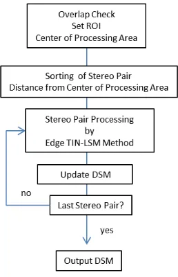
Figure 6 shows the processing flow of reconstruction of DSM. At the first, In order to obtain processing area, overlap area of all images is checked. From this procedure, the region of interest (ROI) of processing area is determined. As the next step, stereo pairs are sorted in order of distance from the center of ROI. The stereo matching process is performed from the center of ROI towards outside. In order to reduce the cost of stereo matching, the Extended Edge TIN-LSM method for each stereo pair is performed only for the new area of DSM.
Figure 6. Processing Flow of Reconstruction of DSM
The Extended Edge TIN-LSM perform as follows,
1. Firstly, parallelizing of stereo image along epipolar line is performed.
2. In order to reconstruct the shape around steep edges of topography or buildings, the edge detection using the Sobel operator is performed on left image. In addition, the important features of edge such as corner or end point are obtained.
3. The matching of these edge features are performed by the OCM along epipolar line on right image. The search area of OCM for edge features are optimized by 3d coordinate
of pass points obtained in previous bundle adjustment process.
4. The production of initial TIN is performed using these feature points of edge and pass points.
5. Moreover, the grid point generation using LSM is performed as coarse to fine process. The LSM of grid points in each step of coarse to fine procedure is constrained by TIN. In addition, the TIN is updated using grid matching results in each step.
6. The new generated DSM area is merged to previously generated DSM.
These procedures are repeated for all stereo pairs. Finally, whole DSM of ROI is obtained.
4. EXPERIMENT
We describe about the experiment of our proposed method in this section. In order to evaluate the effectiveness of our proposed method, we have performed some experiments in test field. Details of experiment are as follows.
4.1 Micro UAV of This Experiment
Figure 7 shows the Micro UAV of our experiments and Table 1 shows the specification of our Micro UAV. Table 2 shows the specification of the 16-mega pixel Digital Still Camera mounted on Micro UAV. The Micro UAV of this experiment has the ability of autonomous flight. The waypoints were planned as considering the image overlap. We planned image overlap as 80% and the side lap of each flight line was 70%. The above ground level of each flight is about 60m. In this case, the base line of each image needs about 12 m and distance of each flight line needs about 13m. The shutter of digital camera was controlled by its own interval timer because the steady hovering flight generally needs more long time than continuous flight.
Figure 7. Micro UAV
Frame EnRoute Zion Pro800
Controller 3D robotics APM 2.5
GPS u-blox LEA-6H
GPS L1 frequency, C/A Code GALILEO Open Service L1 frequency
SBAS surport 2.5 m CEP
Payload 4kg
Table 1. Specification of Micro UAV The International Archives of the Photogrammetry, Remote Sensing and Spatial Information Sciences, Volume XL-5, 2014
Name Olympus E-PM1
Lens f=17mm (View Angle 53°)
Image Size 4032x3024 pixel jpeg
Sensor size 17.3mm×13.0mm
Pixel Size 4.290675 μm
Ground Resolution 21.41622429 mm@ 60m
Table 2. Specification of Digital Still Camera
4.2 Reconstruction of Terrain and Buildings
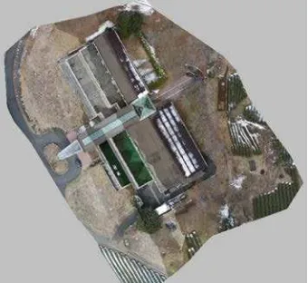
Figure 8 shows the reconstruction result of DSM of our proposed method in first test site. This test site includes terrain and buildings. Our purpose was reconstruction shape of building and terrain simultaneously. The width and height of this test site was about 82 m x 113m and 156 images were used for automatic procedure. The automatic processing time (not include GCP measurement) was 1 hour 25 minutes. In this case, Grid pitch of DSM was 50 cm. However, the edge brake line of buildings and steep edge of terrain have reconstructed as shown in Figure 8. Figure 9 shows the orthoimage obtained from our proposed method.
In order to evaluate the accuracy of our method we construct the reference points by Total Station and RTK–GPS survey. The six reference points are used for GCP and other eight reference points are used for checkpoints. The standard deviation of residual was 13mm in plane and 30 mm in height. The image resolution of Digital still camera of this experiment was 22mm at 60 m flight height. Thus, it is concluded that the result of this experiment has enough accuracy.
Figure 8. DSM of terrain and buildings
Figure 9. Orthoimage
5. CONCLUSION
We have proposed the automatic photogrammetry procedure optimized for low-cost Micro UAV. The feature point tracking procedure based on OC image processing have improved by using position and attitude information from low-cost GPS-IMU information. Therefore, the estimation of homography between each image has started from good assumption. This improvement reduces the processing cost, and improves the stability of tracking procedure. Moreover, the extended bundle adjustment using both GCP and low accuracy GPS has been proposed. In order to obtain the precise DSM, we have performed the application of the Extended Edge TIN-LSM method. The good ability for steep edge reconstruction of the Extended Edge TIN-LSM method has been described through the experiment. Additionally, the accuracy assessment of our proposed method has been described. From these investigation, it is concluded that the proposed method have ability of creating the precise DSM from images obtained from Micro UAV. However, some problems remain for more fully automatic procedure. For example, automatic measurement of GCP image coordinate is still important issue.
REFERENCES
Remondino, F. et. al., 2011. UAV photogrammetry for mapping and 3D modeling Current status and future perspectives. International Archives of Photogrammetry, Remote Sensing and Spatial Information Sciences, Vol. 38(1/C22). ISPRS Confernce UAV-g, Zurich, Switzerland.
D, G, Lowe. 2004. Distinctive image features from scale-invariant keypoints. International Journal of Computer Vision, 60(2). pp91-110.
Lourakis, Manolis IA, and Antonis A. Argyros., 2009, SBA: A software package for generic sparse bundle adjustment., ACM Transactions on Mathematical Software (TOMS) 36.1: 2.
Ullah, F., Kaneko, S., and Igarashi, S., 2001. Orientation code matching for robust object search, IEICE Trans. of Inf. & Sys, E84-D(8), pp.999-1006.
Takauji, H., Kaneko, S. and Tanaka, T. 2005. Robust tagging in strange circumstance. The Transactions of the Institute of Electrical Engineers of Japan (C) 125(6), pp. 926–934. (in Japanese).
Anai, T. Fukaya, N., et. al. 2010. Application of Orientation Code Matching for Structure from Motion. Proceedings of the ISPRS Commission V Mid-Term Symposium. Vol XXXVIII, Part 5. pp33-38
Anai, T., Sasaki, T., et. al., 2012. Automatic Exterior Orientation Procedure for Low-Cost UAV Photogrammetry using Video Image Tracking Technique and GPS Information, ISPRS, Vol.XXIX-B7,V/I, pp. 469-474.
Kochi, N., Ito, T., Kitamura, T., and Kaneko, S., 2012. Development of 3D Image Measurement System and Stereo-Matching Method, and Its Archaeological Measurement. Electronics and Communications in Japan, Vol. 96, No. 6, 2013. Translated from Denki Gakkai Ronbunshi, Vol. 132-C, No. 3, March 2012, pp. 391–400