Copyright © 1993-2001, Hugh Jack
Overview: This note set is part of a larger collection of materials available at http://claymore.engi-neer.gvsu.edu. You are welcome to use the material under the license provided at http://clay-more.engineer.gvsu.edu/eod/global/copyrght.html. As always any feedback you can provide will be welcomed.
This section last updated: August 14, 2006
Copyright © 1993-2006, Hugh Jack
EGR 450
Manufacturing Controls
Padnos School of Engineering Grand Valley State University
Lab Manual
Summer 2008
Jumping and Subroutines - - - 66
CONTROLLOGIX ADVANCED TUTORIALS ... 73
ADVANCED INSTRUCTIONS - - - 73
DVT CAMERA TUTORIAL ... 106
Academic Unit: Product Design and Manufacturing - School of Engineering
Semester: Summer 2008
Class Times: noon-2 pm - Mon, Wed, Fri, first half of semester ****
Lab Times: Tues, 8:30-11:30am, 1-4pm, full semester ****
Instructor: Dr. Hugh Jack
office: KEN 325
office hours: 11am-noon M, W, F first half of semester
phone: (616) 331-6755
fax: (616) 331-7215
email: [email protected]
web: http://claymore.engineer.gvsu.edu
Description: An introduction to the control of machines and processes widely used in manufacturing. Topics include programmable logic controllers, actuators and sensor for discrete and continuous systems, structured design techniques, memory structures, data handling functions, A/D and D/A converters, data communications, and hierarchical control. The technical issues involved in implementing control schemes are presented. (3-0-3). Four credits.
Offered spring-summer semester.
Prerequisites: EGR 345
Textbooks: Jack, H. Automated Manufacturing Systems; PLCs, 2008, Version 5.1.
Reference: Erikson, K.T., “Programmable Logic Controllers: An Emphasis on Design and Application”, http://www.dogwoodvalleypress.com, 2005.
Software: Web Browser
PLC programming software FTP Client
RSLogix 5000 (note demo version available from Allen Bradley website) AutoCad Electrical (http://students7.autodesk.com/?lbon=1)
Objective: When done the student should be able to design and implement control systems for typical industrial problems.
PLC Logic and Connection Sensors and Actuators
2 Combinatorial Logic
3 Sequential Logic
4 Advanced Data Functions
5 Analog I/O and controls
6 Data Communications
Design Issues
Tentative Laboratory Projects: 1. Introduction to micro PLCs
2. Basic ladder logic design and PLC interfacing - combinatorial press control 3. Intermediate ladder logic design and PLC interfacing - encoder controlled motor 4. Advanced ladder logic design and PLC interfacing - sequential traffic lights 5. Introduction to PLC-5s
6. Analog I/O and PID Control
7. PLC Networking and Serial Communications - with DH+ and RS-232C 8. Control of a multistation keytag maker
9. Control of a multistation keytag maker (cont’d) 10. Introduction to embedded controllers
11. Programming embedded controllers
Grading: Laboratories 25%
Project 40%
Tests and Assignments 35%
Tests will be given at natural points during the term as new material is covered. A major final project, involving design, construction and testing, will be proposed early in the term, and be completed later in the term. Marks will be some combination of performance and report. A final examination will be given to conclude the work and test the students global comprehension of the material.
Grading Scale: A 100 - 90
1. INTRODUCTION
1.1 OVERVIEW
• This course addresses a need for a comprehensive examination of modern control techniques found in manufacturing environments. The course will begin with evaluation of PLC’s for dis-crete logic control. The course will then examine PLC usage for more complex control tasks. By the time the course is complete, students will comprehend how these work, and how they can be applied.
1.1.1 Resources
• Manuals for ALL of the equipment can be found at “www.ab.com”. This will include manuals for,
Micrologix
PLC/5 processors, I/O card, etc (bulletin 1771) RSLogix software
1.2 PROJECT
Objective: Students will learn how to synthesize a control system by selecting and building a complete control system from beginning to end.
Method: The basic steps are outlined below, 1. Course begins.
2. Students (individuals or groups) will submit a proposal for a project within the first three weeks.
3. The instructor will review the proposal, and suggest changes as necessary. 4. During the term students will design, build and test their proposed projects.
5. In the last week of classes the final project will be demonstrated and formally presented. Reports are to be posted to the students web page before this presentation.
Notes:
- previous project reports can be seen via the course web pages.
- projects will involve construction and testing, except in unusual cases. - NOTE: projects must work to receive a passing grade.
• Brief descriptions of student projects follow.
• Previous topics for this or similar courses were,
Adams - Wheelchair Pressure Measurement - A system will be designed and built to mea-sure the presmea-sure on a wheelchair seat pad over time, and log these values to a file. The data will be used to design a system that will apply and release pressure. Afrik, T., Hedman, M., Howe, M., Jousma, T., Muckey, L., Postema, J., Thelen, J. -
ASME Student Design Competition - An entry for the competition will be con-ceived, designs and built with the intention of entering (and winning) the 2000 ASME Student Design competition.
Agnello - Customer Counter - A counter will be designed to detect the number of visitors to an archery range. This will be done with sensors arranged to count visitors. A system will be used to count visitors during variable periods. A PLC has been pro-posed, but other options are worth considering.
Andrevska - Fuzzy Logic Controller - A fuzzy logic controller will be designed and imple-mented using a Basic Stamp II chip. The controller will position a DC motor. Baksik & Vinch - SoftLogix For Control of Material Handling Via Devicenet - A
Devicenet based control system for a material handling system will be designed, purchased and built. The main system will be based around an AB SoftLogix con-troller.
Beard - Car Alarm - A car alarm will be designed and constructed using basic logic ICs and other circuitry to drive the actuators and sensors.
Bennett, Dunklin, Workman & Williams - Gumball Machine - A gumball will drop into a merry go round, go up an elevator, roll down a spiral track, be lifted in a bucket, bounce off a trampoline, and bounce out to be delivered.
Bernreuter - Water Heater Test System - A control system will be designed for testing water heaters. The focus of this project will be to use the alternate programming methods in the IEC-61131-3 PLC programming standard.
Beute - An Automated Drill - a fully automated drill press will be designed and con-structed. Air cylinders and contact switches will be used.
Bialk - Control of Conveyor - A conveyor system that was designed and build for EGR 409/367 will have controls added so that it may be controlled from a PLC. This will include the use of a divertor that may be used to sort packages based on size. Bleeker, Deemter, Elzinga - Oven Temperature Control - Controls hardware and software
will be designed and implemented for an oven with different temperature zones. Bouwhuis - Industrial PLC Training Materials - A PLC trainer board will be developed
and built. Training materials will also be developed. These will be used by a local manufacturer to train hourly employees in the use and debugging of PLCs.
Brinkman - Audio Amp Cooler - A temperature sensor will be used to detect the tempera-ture of a car audio amplifier. Circuitry will be designed and constructed to drive a cooling fan.
Brinks - Automatic Back Gage Setting - This project will involve the evaluation of a back gage system that exists on a shearing machine. An automatic control system will be selected and implemented to allow users to control the depth setting with a key-pad entry.
central PC to control devices in a house. A user interface will be designed, along with interface software to control the devices.
Bronkema - Automated House - A unit will be designed and built to allow control of an automated house using an embedded controller. This will monitor external lights, control lights, and allow house status reporting.
Brown, Miersen, Timmer - Basketball Arcade Game - An arcade version of a basketball game will be designed to store balls, and release them for a limited game time. Within the allowed time the user will have to make as many baskets as possible, and the count will be displayed with a status light.
Bultman - Automated Spot Light - A controller for a remote spotlight will be designed and constructed to allow adjustment via remote control, or adjustment via remote con-trol. (Note: as proposed this project is too simple)
Buter - Defect Detection System - A system will be devised to detect a non-critical screw on an automotive floor console. If a missing screw is detected, an operator console will warn an operator to take corrective actions.
Burgess, S., DeBoer, M. - PLC Control of a Welding Station - A PLC will be integrated and programmed to control all aspects of a welding station. Issues to be considered include cycle times, safety, and manual/automatic modes.
Campeau - Hanging Tab Machine - A PLC with appropriate sensors and actuators will be used to add hanging tags to medical pouches. A machine for adding the pouches had been purchased and will be used to add the tags.
Chan, Sedine - Automated Bartender - A PLC will be used to prepare mixed drinks. The user will be able to select the proportions or drink type and the final product will be delivered.
Clark, Dohm, Dyer, Steinke, Valenzuela - ASME Design Competition - An entry will be developed for the ASME 2002 Student Design Competition. This will be devel-oped within the given rules, and be working at the completion of the course Conner - Controls for a Stretching and Stapling Machine - The controls for a material
stretching and stapling machine will be designed and implemented using a Micrologix 1500 and RS-Logix software.
Cooke, Humphrey - Timer System for Pinewood Derby Track - A timer system will be developed with a 6811 processors for a pinewood derby track.
Cowan - PLC Retrofit of Taping Machine - A PLC will be selected to replace an existing controller on a machine that creates a tape of screws. This will also require some redesign of the machine.
Cummings - Automatic Fishing Pole - An ice fishing pole will be fitted with control sys-tem that will watch to see when a fish has hit. When the fish has been detected the line will be slowly reeled in.
Curtis - Expansion Unit for Automatic Sprinkler Controller - A system will be designed that will ‘piggy back’ onto an existing sprinkler system. This will use the last set state to then switch on a supplemental state for the additional zones.
Davis - Screw Machine Control - A set of limit gages will be designed for a screw machine. The gages will test completed parts, and allow out of tolerance parts to be diverted. Visual basic and a PLC will be used for control.
evaluate repeatability of motions. This will include devices for ball trajectory and club
Dejong, McKervey - A Really Fancy Pencil Dispenser - A pencil dispenser with a few Rube Goldberg twists.
DeJonge - Control of a Heat Stake Machine - Controls for a heat stake machine will be designed and built for a local company. This will involve the design of all electri-cal components, working with trades to get electrielectri-cal and mechanielectri-cal work done, and final programming of the machine.
DeVos, Karlesky, Kuieck - A Ground Breaking Robot - A hydraulically controlled robot will be designed and built for the ground breaking for the Keller Engineering Building. The robot will be controlled by a VR glove to allow a dignitary to guide the robot to break ground.
DeVries - Train Set Controller - An automatic train set controller will be designed so that a train set will run automatically, including switch track, lights, etc.
Dodge, Eddy, Oostdyk, Spikes - Art for New Building - This project will use equipment that is already owned by the school to develop an artistic display for the Keller Engineering building.
Dood, Fleischman, Sanford, Kozikoski - “Sip-and-Puff” Fishing System - An entry will be designed and built for the 2001 ASME design competition.
Duncan, Nicola, Vergas, “PLC Control of an AGV”, The chassis of an Automated Guided Vehicle has been constructed in the past. It has since been superseded by another vehicle. But, with the addition of some mechanical and electrical components, this AGV was restored to working order.
Eissa - PLC Control of Assembly Fixture - An assembly fixture that will be used by a local company to assemble machine that will uses a number of slides, pins and other actuators to assemble a panel. This project will involve the design and con-struction/implementation of all wiring and programming.
Emery - Stereo Amplifier Overheat Control - A basic controller will be used to monitor the temperature of a car audio amplifier. When the amplifier temperature rises too much the amplifier will be shut off, or the power output decreased. A PLC may be too expensive for this application.
Endres - FMEA for Chlorine Scrubber Control - A control system was previously con-structed that will scrub chlorine gas in the event of a leak. There are numerous sen-sors and actuators to be considered.
Essenburg, McDaniel, Thompson, Vandenbrink - Pinball Machine Controller Retrofit - A pinbal machine will be retrofit with a PLC for control. The score display unit will also be replaced. The project involves all electrical work, programming, and an aesthetically pleasing finish.
Evans, W., VanEss, J. - Material Handling System Project - Various components for a mini manufacturing system will be designed and constructed. These functions will probably include a wood metering and cutting station, and a marble feeding sta-tion. This will complement the activities of the students in EGR 474.
Fett - Shifter Test Apparatus - A Labview controlled test machine will be developed that will cycle an automotive shifter. Labview will be used to make some adaptations to the test strategy and analyze the results. Final data values will be output to data-base files.
Frazee - SPC Testing in a Screw Machine - A screw machine has had a gauge added, but requires a diverter system for bad parts. The project involves designing and build-ing a diverter system, and developbuild-ing a control program to detect and eradicate unacceptable parts.
Frei, Meneses - Injector Control System - The system will inflate an artificial lung through a process that involves partial inflation, with pauses. A variable position valve will be used to change the flowrate as the lung fills. The system will be PLC based. More details are required soon.
Gallatin, Jousma, Karabelski - A Small Work Cell - Equipment that was originally devel-oped in EGR 409/367 will be refit and used to construct a small workcell. The task of the cell will be to handle cans and drill holes in them.
Gehrke - Paint Line Model - A small model of a dip paint line with an overhead conveyor. There will be three stops on the line.
Glass & Werdon - Corner Cutter - A device will be designed that automatically rounds the corners on lexan keytags.
Goosen, Hills - Carnival Game Controller - A system will be devised to watch targets that have been set up. When balls are thrown the targets will be knocked down. A score display will be used, and a winner siren will be enabled. A PLC may be too expen-sive an option for this project.
Grimshaw, Hupcik - Upgrade of The Keytag Maker - The keytag maker will be updated including refitting it with new sensors to detect the holes in the plastic strip, replac-ing the current servo control system with an Ultra 100 unit. The project will also consider the feasibility of changes to the keytag rounder.
Gutierez, Williams - Redesign and Control of Sketching Device - An existing device for doing simple sketches will be redesigned mechanically and electrically so that it may be controlled with a PLC. The final unit will use optical sensors so that it may be operated behind a window.
Hansen - Servo Driven Bumper Cutoff - An existing system uses hydraulics to cut auto-mobile bumpers. This system will be retrofit with a servo drive cutter so that the cutting blade stroke can be adjusted as the cutting blade wears. The operator will be able to control the blade stroke using an HMI.
Hart, J., Kern, E., Maas, C. - Automatic Hose Cutter - A machine will be design and built to allow hoses to be fed variable lengths and cut automatically. A keypad will be used to set the length, and a blade will be used to cut the hose.
Hitchcock - A Table Height Cycling Test Stand - A control system will be developed and built that can cycle table height adjusters for a fixed number of cycles. The system may drive either pneumatic cylinders or motors to drive the tables. A proximity sensor will be used to mark the end of the travel. Adjustments will be included to allow the height settings to be changed without reprogramming the PLC.
Hornacek & Tietz - RC Car Controlled by 68HC11 and Sensors
drops below a set point the secondary fermentation vessel will be cleansed with a bleach solution, rinsed, and then the wort in the primary will be pumped across. Floats will be used for fluid levels. A micro PLC will be used for control.
Hultman - Drag Racing Timer System - A drag racing timer system will be designed with the ‘christmas tree’ and a digital display to indicate time and speed. The system will involve the design an construction of required circuitry and software develop-ment. The system will be based on a 68HC11 microcontroller.
Ivanov - PLC Demonstration Unit - A SLC-500 demonstration board will be designed and constructed. The board will include analog inputs, and motor.
Jamison - Animatronics - Anthropomorphic robotics will be designed and built. Through control they will exhibit lifelike features. This project may be too ambitious. Johnson - PLC control of weld data quality - A system will be designed to watch signals
coming from a welding station. These signals will indicate when a weld is good or bad. The PLC will use experimental parameters to determine the weld quality. An external display will be used to display information about weld quality.
Johnson - Satellite Dish Positioning System - A model of a satellite dish will be con-structed. A motor will be controlled to reposition the dish via a user interface. Kaye - Drag Racing Christmas Tree - A simulator unit for drag racing start lights will be
constructed to allow drivers to improve reaction start of a run. A mini PLC will serve as the heart of this system, and will vary the light times in accordance with the national regulations.
Klein, J. - Temperature Control Unit - A unit will be designed an built to monitor temper-ature and switch a fan on/off when upper/lower tempertemper-ature limits are reached. The unit will be based on basic discrete electronics.
Klynstra - Crash Test Calibration and Control - A hydraulically driven crash test unit will use a Labtech program to calibrate and control the unit to ensure a precise impact velocity.
Knibbe, R. - Home Timing Unit - A clock module will be purchased and used as the core of system that will turn on room lights, fan, etc. External circuitry will be designed and built to allow the user to turn on the light independent of the clock.
Koperski, C., Powell, M., Schutter, N. - Skee Ball Machine - A machine will be designed for Skee Ball. When balls are rolled they will fall into one of four holes. While the game is active balls will be returned. Points will be totaled and displayed with an LED display. A light and siren will be turned on for a winning score.
Kunzi, B., Thomas, J. - Parts feeder for the EGR474 material handling system.
Lamfers, A. - A PLC Based Home Security System - An Allen Bradley SLC-1504 will be used for a home security system. This will include sensors on various doors and windows, and a light and alarm that will be triggered when there is an intrusion. The alarm will have arm/disarm functions and zone control.
Langendoen, Vermaire - Golf Game - A golf game will be designed that will allow balls to hit into cups. Scores will be tabulated and output on an LED display. A switch set-ting will allow the user to select various game option.
Langston, S. - Programming Package for Ladder Logic Simulation - A package will be written in C to simulate ladder logic. The program could be entered in a number of forms, and it will allow the user to change inputs and observe the results.
automatically detect balls and strikes. The system will score the game and display the results on a display.
Likic - Automated Model Home - A model home will be built and controlled with a PLC. One major feature will be a security system that uses various sensors.
Ljubic, Ngui, “Control of a Rhino Robot with an Allen-Bradley PLC-5”, A rhino robot was in working condition, but lacked controls. Control via a PLC and a new key-pad was added to allow direct control, and program execution of movements. Lubbers, J., Scholten, J. - Container Changer for Production Equipment - An automated
tote changer will be added to a production machine (makes elbows?). This will use pneumatics to drive a new mechanism to load and unload totes from the machine. Magee, M. - Constant Volume Reheat System - A small model with 3 rooms will be
con-trolled for temperature, pressure and humidity. The system will use heating ele-ments, and various control elements to adapt system behavior to compensate for different room settings and seasonal variations.
Mathews - Retrofit of a Dumpster Testing Station - An existing system is used by a local manufacturers to test dumpsters by filling them with a load, and then dumping the contents out repeatedly. The machine needs to be updated to meet new test stan-dards. This will involve redesign of some of the mechanical and electrical systems. The program in the PLC will be updated to reflect the changes to the system. Maschewske - Extrusion Monitoring Station - A system will be designed and build for a
company to monitor an extrusion station. This will monitor process variables (how?) and then display messages on a scrolling LED screen. The project will involve the design, partial wiring and programming of the system.
McInally, Wood - Automatic Camera Platform - A camera positioning system will be designed and built. This system will use a Basic Stamp chip to interface to a PC computer through a serial port.
McJones - Control of Automatic Tool Changer - A CNC machine tool has been fitted with an open architecture controller. This controller does not control the automatic tool changer. To get this functionality a PLC will be added to the system to control the tool changer. This will involve control of the magazine, and loading arm. The PLC will communicate with the CNC controller (via RS232?) to determine when a tool is to be changed.
McMullan, A., Mose, D. - Sprinter Timer - A timing system will be designed and built. The basic function will be to be tripped at the start line for a sprint, and stopped at the end of the distance. The elapsed time will be displayed on an LED readout. Mead - Use of PLC to Control Indexing Table - An existing indexing table uses hard
wired controls. A PLC will be used to control the table, and allow the user to pro-gram parameters.
Miller - Starship - An actuated model of the starship Voyager.
Moelker, N. - Travelling Sprinkler Stop -A system will be designed, built and installed to monitor a moving sprinkler. When it passes a certain distance a sensor will detect this limit and close a valve on the water main. This system should include appro-priate start/stop/reset buttons, along with an optical sensor to determine when the sprinkler has reached the end of travel.
Moore - Electric Wheelchair - An existing wheelchair will be refurbished and tested. Additional work will be done to add a pressure switch to ensure a rider is in the chair, and a battery low indicator.
Morgan, Uken - Drag Tank Retrofit - A drag controller will be designed and built for the drag tank in EC713. This unit will allow a target speed to be specified, and also read the actual drag speed.
Morrell - Vision Directed Control of a Robot - A DVT vision system will be configured and setup to control a Fanuc RJ-2 robot. The vision system will compare scenes to determine part offset. Offset and orientation vectors will be sent to the robot via an RS-232. The robot will then adapt to the location and orientation of the part. This will be a prototype system, so statistical tests of performance will be done.
Munster - Vision Control System - A proof of concept system will be developed around a vision system. The vision system will locate an object in a field of view. The loca-tion will be sent over a serial cable to direct an x-y posiloca-tioning axis. An HMI will be added to allow limited user interaction, and simple reporting.
Muthucumarasamy, Porter, “PLC Programming for a Material Handling System”, A sys-tem was donated to Ryerson. The syssys-tem was previously assembled, and basic pro-graming of the PLC was done. This project completed the programming.
Nahin - Design and Construction of NC - This multi part project will begin with the design of mechanical and control system for a small NC lathe. In future course projects this will be outfitted with a control computer.
Nink & Seco - An External Keypad Based Car Door Lock - A Car door locking/unlocking system will be designed and built around an Altera based controller. This system will have a keypad mounted outside the car with a keycode to lock and unlock the driver door. When an incorrect code is entered a horn and lights will be activated. Olthof - Train Set Controller - An automated train set controller will be designed and built.
This will allow switching of tracks, coordination of lights, power switching to tracks, etc. The type of controller must be determined.
Palmbos, E. - Retrofit of House Electrical Control System - The current house uses 24Vdc to drive relays at the lights to switch 115Vac. The relays are starting to fail, and a redesign is needed. Replacement relays will be found and a rectified voltage will be used to control them.
Peterson - Bedroom Security System - An alarm system for a single room will be devel-oped to monitor motion. Knocks will be required before entry is permitted. The system will be controlled with a Mitsubishi PLC.
Phoa, “A PLC controlled Box Orientation Device”, The existing system was put in work-ing order, and the PLC was programmed to ensure complete functionality of the device.
Remelts - Automatic Guitar Tuner
Rollenhagen - Home Security System - A home security system based on the Basic Stamp chip will monitor various inputs. In the event of an alarm, it will turn on a siren for a set time and then reset.
Rutgers - Automatic Guitar Tuner
Schmitt - Remote Control of Car With PC
future by the electric race team.
Scott - Hatchback Unlatch Mechanism - A hatchback controller for a small car will be designed so that it will latch/unlatch automatically. A remote control will also be considered.
Seaver - Thermoforming Process Controller - An existing thermoforming machine will be retrofit with a system to load and unload a blank from the oven with variable cycle times.
Semeyn - A Carpet Cutting Machine - A controller will be added to a machine, and pro-grammed, to pull the correct carpet length from a roll, cut it, then place the carpet on the part to be molded together.
Serebryakov - Speaker Directivity Index Measurement - A turntable arrangement will be developed to support hardware and software for measuring speaker loudness at various angles. This apparatus will use a PLC to position the table as requested. Sham, Sutander, “PLC Control of an Automated House”, A house was developed with a
number of automated systems. These allowed windows, doors etc to be opened/ closed to meet changing environmental conditions. The system will also include other useful features such as a burglar alarm.
Sietsema - Car Alarm - A car alarm will be designed and constructed.
Silcox - Cat Feeder - An automate cat feeder will dispense food at regular intervals as con-trolled by an electromechanical timer. A sensor will stop the feeding cycle if food remains in the dish. Another sensors will be used to indicate when the food hopper is empty.
Singhal, M. - Computer Controlled Model Railroad- A three part system will be design and implemented. There will be a Visual Basic program at the front end that will allow the user to specify actions and monitor status. An RS232 connection to a Basic Stamp chip will communicate commands, and the Basic stamp chip will control the train set. Functions will include train speed, switch tracks, etc.
Smith, Tang, “Traffic Light Control for Optimal Flow”, Multiple sets of traffic lights were constructed, and controlled via a PLC. The Control programs in the PLC were such that the traffic lights adapt to nonuniform traffic flow.
Springer, T. - Table Lifting Machine - Controls for a machine will be designed and imple-mented to clamp and raise a work surface. There will actually be two independent work surfaces.
Turner - PLC Control of Waterjet Machine - A waterjet machine controlled by PLC will be reprogrammed. The goal will be to allow cutting of one or more parts in foam. Tuttle - PLC - A 6811 will be used to implement a simple PLC
Ulbikas, Chetcuti, “Upgrade of PLC controlled robot”, An existing robot that is connected to a PLC was put back in working order, and a keypad was added for direct, and programmed control of the robot.
Vanderkolk - LabVIEW Interface To Dynamometer - LabVIEW will be interfaced to a cutting force dynamometer. The cutting forces will be displayed for easy reading, and graphs of values may be written to files.
Vidinlic - Upgrade of Assembly Station - An assembly station will be upgraded for a local company to include two new sensors, a manual switch and an updated program to ????.
and actuators. A PLC was used to control various function such as a security key-pad, driers, belt, wax, etc.
Wiersma, Stehouwer - Keytag Corner Rounder - Retrofitting for a keytag rounder will be completed so that it is fully automated. This will include a chute for incoming parts, an automate clamping mechanism, etc.
Wong, Kan, “Design and Control of a Conveyor Offloading Robot”, A robot was
designed, built and controlled by a PLC for sweeping objects off a conveyor belt. Woodard - Flooding Alarm - An alarm will be developed to detect flooding in a house in
the event of power failure. This device will need to detect when the house power is off, and when water is present.
1.2.2 Final Project Requirements
• The final requirements for the projects are list below. Unless you have been specifically and deliberately told to otherwise, use these as requirements.
1. A demonstration of your working project.
This will be on the same day as the senior project presentations.
Some students may use videos of their projects by prior arrangements with the instructor.
The projects are to be set up in EC 713. Other spaces are available on request. Those requiring air supplies, or 220Vac will be in EC713 only. If you have these
need, speak to Bob beforehand to make sure you will have them.
Have the demonstrations set up BEFORE 11am. They can be taken down after the Ring ceremony.
Have the demonstrations taken down, and all parts returned by Monday. You are expected to be at your display between 2pm and 3:30pm. 2. You will need to present a poster for your project.
This will be similar to the poster for your senior project. See an example in the EC718 conference room if necessary. These should be neatly done. I suggest that you use “foam core” board that will support itself.
Use a table available in one of the class rooms. 3. A report that is posted to the web.
For teams, the report can be posted to one homepage, and links added by other stu-dents on the team.
A project without a report will not be accepted. The report should be posted before the demonstration.
The report should contain technical details. Keep in mind that when you are gone another student may want to use your report. The more questions they need to ask, the lower your grade.
Add digital photographs, schematics, etc. to illustrate what you have done. Examples of previous reports can be found at,
http://claymore.engineer.gvsu.edu/~vincha/index.html/page2.html http://claymore.engineer.gvsu.edu/~morrells/egr450.html
http://claymore.engineer.gvsu.edu/~devosr/450project
1.3 LABORATORY EXPERIMENT GUIDELINES
General Objective of Laboratories:
The laboratory experiments will allow the student to apply the theoretical techniques learned during this and previous controls courses. While implementing the theoret-ical controls techniques, the students will also learn the practtheoret-ical aspects of modern controls technologies. The first labs will introduce the student to Programmable Logic Controllers. The final labs will focus on advanced applications and control of a small scale industrial process.
• Notes:
1. Prelabs are essential, and must be done before every lab session when required. 2. Prelabs require that some assumptions be made.
3. The lab period should be used for debugging prelab work. 4. Labs are to be handed in before leaving.
5. Prelabs for individual labs are to be done individually. Prelabs for group labs are to be done in groups.
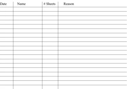
• The projects sheets that are in the lab notes are to be filled out as follows,
PLC Project sheet - identifies the project, packet contents and contact person. Project Notes:
System Description - a succinct paragraph stating how the system will behave I/O Notes - description of all inputs and outputs.
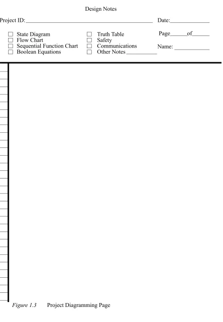
Design Notes - A detailed description f the control system. This description must be in the form of a state diagram, flow cart, sequential function chart, Boolean equations or ruth table.
Application Notes - For our use this page will usually contain a test plan. A test plan lists the test cases needed to verify correct operation of the system. Each test case con-sists of a set of inputs and the corresponding outputs. A complete test plan ensures proper operation of the system in all states.
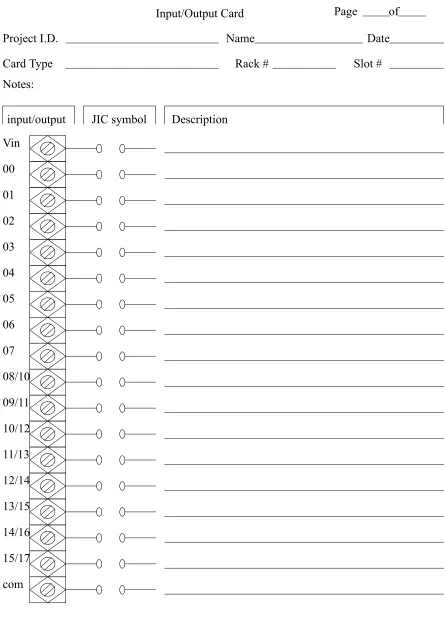
Input/Output Card - Detailed plan for attaching the inputs and outputs to the PLC. Program Listing - A list of ladder logic to implement the system.
• NOTE: IN ORDER TO COMPLETE LABS IN THE TIME ALLOTED THE PRELAB WORK MUST BE COMPLETED BEFORE ATTEMPTING THE LAB EXERCISE
• general rules for using the design sheets are, - omit unused design sheets
- if a small change is made, modify the design sheets
2. LABORATORY ACTIVITIES
2.1 Lab 1a - Introduction to SoftLogix Controllers
Objective:
To learn the basic operation of Allen-Bradley SoftLogic controllers.
Pre-Lab: None.
Resources: SoftLogix 5800 Software, and Ethernet/IP hardware manuals (www.ab.com)
Equipment:
As provided
Procedure:
1. Follow the SoftLogix tutorial later in the notes.
Submission:
1. A pass grade will be assigned to students that complete the tutorial and print out the final program in the tutorial.
2.2 Lab 1b - System Wiring and Programming
Objective:
To wire an advanced control system and write combinatorial ladder logic programs.
Electrical Description:
This lab will involve wiring 115Vac from a building supply. Some special items must be noted.
1. DO NOT CONNECT THE SYSTEM UNTIL all wires have been connected and checked.
2. Make sure the ground is connected to all devices.These are typically color coded as green, or have a ground symbol. Note: power should not flow through the ground, it is only for emergencies to draw current out of the cases of electrical equipment, and into the ground beneath the building. In other words the ground and common are not the same thing.
switched off, making electrical shocks less likely. Note: in reality, even if these wires are backwards the power will still be delivered to the load.
4. After connecting the power to the devices, it is a good idea to plug them in and check operation before proceeding to connecting other devices.
5. Try not to daisy chain power connections (like a string of christmas lights), but connect the power cord to a terminal strip (power bus), and then connect to each device to the terminal strip. (see the figure)
6. Do not leave loose, or exposed wires. These will only lead to short circuits, elec-tric shocks, or other problems. Tighten the wires. If doing this for permanent jobs, the wire should also wrap around the screw. Note: leads with banana plugs or ALIGATOR CLIPS ARE PARTICULARLY PRONE TO CREATING SHORT CIRCUITS.
Inputs and outputs also require a few notes:
1. A PLC rarely has an internal power supply for inputs or outputs. You must always connect an external power supply for inputs or outputs.
2. The ground and common are terms that are badly confused/misused. A true ground is an electrical connection to the ground beneath a building that will draw away current if there is an electrical fault. A common is a reference voltage for all parts of a circuit, typically 0V. When connecting devices such as sensors and actuators we want to connect them to a common. This problem is normally overlooked, but when we have systems with mixed power sources (eg. 115Vac, low voltage DC) we must separate these. Do not connect the common to the ground. BE WARNED, many low voltage devices (such as power supplies, sen-sors, etc.) show the common as a ground.
3. Remember for relay outputs there is no common, the output is just a switch.
The system is wired to include an estop that will cut the power to the outputs, but allow the plc and inputs to continue working.
Pre-Lab (Done individually)(NOTE: These, and all other Pre-labs will be checked before every lab. A mark of zero will be assigned when prelab materials have not been completed before the start of the laboratory):
1. Review the manuals for the input and output modules for the Flex-IO modules.
2. Prepare a wiring diagram using software. AS A MINIMUN, the wiring diagram should contain the following elements.
- 3 PNP proximity sensors - 2 AC proximity sensors
- start and Estop inputs to disconnect outputs - 3 solenoid outputs for pneumatics
- 2 output lights
- a power supply and requirements for various - all required safety circuitry
3. Write a simple ladder logic program for a task of your own (individual) choosing. Describe the task briefly in words, and then develop a Boolean equation. Other techniques, such as truth tables may be useful. The program should use some/all of the inputs and outputs described in step 1.
Resources: SoftLogix 5800 Software, and Ethernet/IP hardware manuals (www.ab.com)
Equipment:
As provided NPN (sinking)
PNP (sourcing)
V+
V-NPN
V-V+ black PNP
brown
white
brown
Procedure:
1. Connect the circuit as required in the prelab. If necessary, make revisions to the wiring diagram for the final documentation.
2. Each individual on the team should enter and test their ladder logic program.
Minimum Submission:
Note: Design sheets must be used, although printouts may be used as alternates. 1. All prelab work
2. Your individual wiring diagram, and the diagram used by the group, with all revisions made.
Figure 1.1 Design Cover Page Project ID:
Start Date:
PLC Project Sheet
Contact Person:
PLC Model:
Attached Materials/Revisions:
Figure 1.2 Project Note Page
Project ID: Date:
Page of
System Description I/O Notes
Project Notes
Power Notes Other Notes
Figure 1.3 Project Diagramming Page
Project ID: Date:
Page of
State Diagram Flow Chart
Sequential Function Chart Boolean Equations
Truth Table Safety
Communications Other Notes Design Notes
Figure 1.4 Project Diagramming and Notes Page
Project ID: Date:
Page of
Test Plan Electrical I/O PLC Modules Other Notes
Application Notes
Figure 1.5 IO Planning Page
Input/Output Card
Project I.D. Name Date
Page
input/output JIC symbol Description
of
Vin
00
01
02
03
04
05
06
07
08/10
09/11
10/12
11/13
12/14
13/15
14/16
15/17
com
Card Type Rack # Slot #
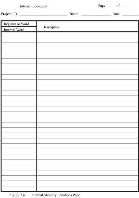
Figure 1.6 Internal Memory Locations Page
Internal Locations Page of
Project I.D. Name Date
Register or Word
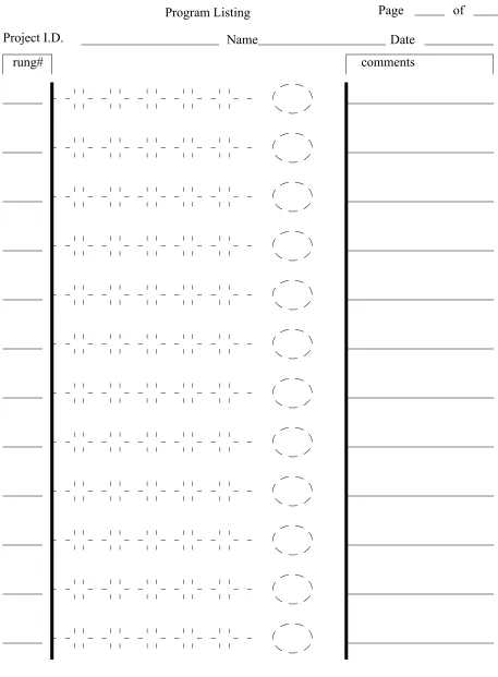
Figure 1.7 Ladder Logic Page
Program Listing
Project I.D. Name
Page of
Date
2.3 Lab 2 - Sequential Logic Control
Objective:
Develop a PLC program that will control a miniature set of traffic lights. These lights will go through a normal sequence, but will have pedestrian cross walk buttons that will activate a cross walk signal when pressed. When done the student should understand the design and implementation of time dependent control circuits.
Pre-Lab: (due at the start of lab period)
1. Draw a state transition diagram for the traffic lights given the process description below. 2. Write the ladder logic model for the state transition diagrams.
3. Develop an exhaustive test table that will test all of the possible transition states for the traffic lights.
Process Description:
We want to develop a controller for a set of traffic lights that is at the cross of Main St. and a less used Cross Rd. The lights under two possible sequences as shown below. In the normal sequence the green for cross is shorter with no cross walk light. If a cross walk button is pushed while the Main light is green or yellow the Cross green light will be on longer with a walk sign.
Cross green 10s
Cross yellow 4s
Main green 20s
Main yellow 4s Walk 10s
Cross green 20s
Cross yellow 4s
Main green 20s
Main yellow 4s Walk 10s
Walk 10s
Equipment:
SoftLogix processor Output lights
Wires
Procedure:
1. The instructor will describe how to connect the PLC, power supply, buttons, etc at the beginning of the laboratory period. As a group you will connect the circuits. Com-ponents used will include push buttons and red/yellow/green output lights.
2. As a group, enter and test the ladder logic for pre-lab 2 and conduct tests in pre-lab 3. The instructor must check the performance.
Submission:
1. Pre-lab and updated laboratory materials.
2.4 Lab 4 - Advanced Programming Topics
Objective:
To learn the advanced programming functions and interfacing.
Pre-Lab: (due at the start of lab period) None.
Equipment:
ControlLogix, Panelview600Plus
Procedure:
(Note: for all tutorials, monitor the contents of the PLC memory to understand what is happening.)
1. Follow the ‘Panelview600Plus’ tutorial.
2. Follow the ‘Advanced ControlLogix Programming’ tutorial.
Submission:
A program that reads an analog input and prints it on the HMI.
2.5 Analog Control
2.5.1 Lab A - Analog Input/Output
Objective:
Pre-Lab: (due at the start of lab period)
1. Write simple programs to read an input voltage and output the same analog voltages from the PLC.
2. Develop the ladder logic to read an analog voltage, perform a calculation, and output the result as an analog voltage. The equation is,
Process Description:
Analog inputs and outputs are done with multipurpose cards in the PLC rack. To control these cards there is some overhead required to set voltage ranges, scales, values, etc. This can be done by setting values in the PLC memory, or by using built in setup functions.
Equipment:
SoftLogix controller and FlexIO rack with an IE4XOE2 analog IO module Computer with RS-Logix programming software
Voltmeters Power Supplies
Procedure:
1. Configure the PLC as normal. Ensure that when setting up the the card the inputs and outputs are set to the -10V to 10V range. The card will also require a 24V supply - refer to the installation manual for additional details.
2. Test the analog output values using a multimeter. Change the output value
(Ch0OutputData) and measure the output voltage. Repeat this for multiple values and record the results in a table. Draw a graph.
3. Supply an input voltage between (but not beyond +/-10V) and record the input voltage and integer value in a table. Then graph the values.
4. Test the program written for prelab step 1.
5. Test the program written for prelab step 2 and test with a multimeter and voltage supply. Use a number of values to confirm.
Submission:
1. Pre-lab and updated laboratory materials.
2.5.2 Lab B - PID Control
Objective:
To explore PID control.
Pre-Lab: (due at the start of lab period)
1. Write simple programs to read and output analog voltages from the PLC and perform PID control of a motor speed.
Process Description:
The basic equation for a PID controller is shown below. This function will try to compen-sate for error in a controlled system (the difference between desired and actual out-put values).
The figure below shows a basic PID controller in block diagram form.
The PID calculation is effectively a calculation in the PLC. One basic method of PID con-trol is i) read voltage, ii) do PID calculation, iii) set output voltage. (Note: it is also common to get a self contained PID card for the PLC that deals with all inputs and outputs). The ladder logic below shows a PID control function.
Equipment:
SoftLogix controller and FlexIO rack with an IE4XOE2 analog IO module Computers with RS-Logix programming software
Voltmeters Power Supplies Motors and drives
Procedure:
1. Connect the PLC to a motor driver (Ultra 100, Ultra 5000 or series 160 VFD).
2. Test the analog output control of the motor by changing output voltage values. Record these with the analog inputs from the tachometer in a table.
3. Use the PID control program to control the motor. Note: you will need to set up param-eters for the PID control memory. By default the values such as scaling and alarms are all off. Note: Make sure that the PID control memory contents are reported.
PID
Control word: Proc Variable:
Control variable:
This calculation uses the feedback variable stored in ‘Proc Variable’ (as read from the analog input). The result is stored in ‘Control Variable’ is the output to drive actuators in the system. The control block ‘pid_control’ needs to be created with the type ‘PID’ and additional configuration values are stored in the data structure. Zeros have been entered for more advanced features that will not be used. (Note: There is a small box with three dots beside the ‘pid_control’ word. It is necessary to click on this to open a configuration window.
Submission:
1. Pre-lab and updated laboratory materials.
2.6 Lab 6- Communications
Objective:
To explore serial communications with a PLC.
Background:
Serial communications can be done using an RS-232 interface, a very common interface. On the CompactLogix CPU there is one RS-232 interface that we can use for serial communication.
Pre-Lab: (due at the start of lab period)
1. Visit the Keyence website and look at the product documentation for the BL-600 series of barcode scanners. One of these will be connected to the serial port on the front of the CompactLogix processor. Note that these require a special cable with wire to provide 5V to power the sensor. Also, the sensor will need to be configured using software also available from the website.
2. You will need to write a ladder logic program to write the string ‘LON’, including car-riage return and line feed, to start the barcode scanner. (Note: do not look directly into the laser - it is a bad idea and you may experience some sort of blindness.) Your program should also read the barcode string returned. The reader should be
AWT (Ascii write) Channel 0
src “ABC$r$l”
Data Stored in memory
--- This will result in ABC being printed on the terminal Source src
Serial Control c String Length 5
This command will write a string to the serial port on the front of the CPU. The string to be written to the port will have to be stored in memory. In this case ASCII string memory (src) can be created to hold it. At this location in memory, we need to manually enter the string. The ‘$r’ and ‘$l’ are for a carriage return and line feed after the string. This is equivalent to pressing the ‘enter’ key on a keyboard.
triggered by a normal input, such as a proximity sensor.
3. The program should compare the barcode to at least two values and detect a pass fail condition. The barcode and the test condition should be displayed on the HMI. If the test fails one pneumatic cylinder should be fired, if not a second will be fired. 4. Develop all wiring and pneumatic diagrams.
Equipment:
CompactLogix controller RS-232 Communication cable Custom cable for BL-600 sensor
Keyence BL-600 series barcode scanner (e.g. BL-651)
Procedure:
1. Make a cable to connect the barcode scanner to a 5V source, and a computer. Note: See the manual.)
2. Connect the barcode scanner to a PC and run the configuration software to setup the scanner. This may require some trial and error effort. Test the sensor using the ‘Monitor’ to verify that you can read bar codes.
3. In RSLogix5000 Set the communication port parameters to match the sensor, and set the port control to ‘USER’. This will allow the PLC to access the serial port. 4. Enter/download your program and verify the operation.
Submission:
1. Pre-lab and updated design work.
2.7 Lab 7 - Messaging
Objective: To use message passing between control systems
Pre-Lab: 1.
Process Description: .
Procedure: 1.
Submission:
2.8 Lab UPDATE- DH+ Communications
Objective:
To explore to and between PLCs.
Pre-Lab: (due at the start of lab period)
1. Write two programs to run on a PLC-5 and a Softlogix PLC. When a button is pushed on one PLC (node #1), it should send data to another PLC to turn on an output. The message should be passed using the DH+ network. Write a second program that uses DH+ to run on a PLC so that when a button is pushed it requests data to set an output.
2. Write a program to send a message out the RS-232 port on the SoftLogix (to a con-nected PC running a terminal program) when an input is active.
Process Description:
As with the previous use of analog input and output cards, we need to set up blocks of memory that contain communication information. These blocks indicate what is to be sent and where.
The Data Highway Plus, DH+, network uses a single path to connect numerous devices. To use this the block of memory below must be used to set up the information to be sent or received.
Block of data stored in memory N7:0
When PLCs communicate, one PLC must write contents of its memory to a second, or one PLC must request contents of memory from a second. The program below shows the basic steps involved in communication.
Message Type: Source Element: Size
Local/Remote Remote Station Link ID
Remote Link type Local Node Addr. Processor Type Dest. Addr.
PLC5 Typed Read n[0]
20 Local N/A N/A N/A 10 PLC-5 N7:23 FOR SoftLogix
MSG
Send/Rec Message Control Block N7:0
Equipment:
Note: the PLCs both need a different DH+ node address, this is set using the jumpers on the back of the PLC-5 cpu card.
Switches 1-3 represent the least significant digit and switches 4 through 7 represent the most significant digit. The settings for node 3 would be
1 2 3 4 5 6 UUDDDD
To connect the devices a three conductor wire is needed. The connection is shown below and the wires are connected to the same terminals on the other PLC(s). The shield ter-minal should be connected to the metal sheath in the wire.
Procedure:
2. (single teams) Have two computers available. One will be used for programming the PLC, and the other will be used as an ASCII terminal. Enter and download the pro-gram to the PLC as normal. Disconnect the serial cable, and connect it to the other PC. Run ‘hyperterm’ and test the program.
Submission:
1. Pre-lab and updated laboratory materials.
2.9 Lab - Keytag Maker
• Partss A, B, C, and D - These four parts are complimentary, and each week there will be four groups that will rotate through all four labs.
• Group Size: 3 students, 4 rotating stations
• These laboratories will be used to pull together 4 individual control systems into a complete manufacturing control system. Although each group will solve a different control problem, each laboratory will end with all stations in a fully functioning control system.
• These four labs will all use an Allen-Bradley PLC-5 to control the stations.
• The descriptions below will be used to develop a design and ladder logic before arriving at the laboratory. All laboratories are to be done on design sheets like those found in the course notes, or equivalent.
• The basic schedule for the first lab is shown below for the first and second weeks. drill
press
material feeder
logo stamping press
shear press plastic
• NOTE: In this lab three of the stations use the hole detect to start an operation. Even when the operation is done the hole in the keytag will remain. You must write your program so that after the press has retracted the process will not start immediately. Only after the hole is gone will the program start looking for a new hole. You might want to add another state that waits until the hole is gone.
2.9.1 Part A - Shear Press
Objective:
A PLC will be used for control of a hydraulic cylinder that will shear off keytags.
Pre-Lab:
1. Examine the other components in the lab and determine what is required for proper operation of the shear.
2. Design the controls for the press.
Process Description:
The shear press will detect when the material is in place for shearing when a hole is detected by an optical sensor mounted. When sensed it will set a bit true in mem-ory (B3:0/0) that will cause the material feeder to stop. A pneumatic cylinder will be actuated to clamp the strip. At this point shearing will begin by advancing the hydraulic cylinder until a hydraulic cylinder advanced limit switch is actuated. At this point the advance solenoid will be turned off, and the return cylinder solenoid will be actuated. This will continue until the retracted limit switch is actuated. At this point both the hydraulic solenoids are turned off. Finally the pneumatic sole-noid is released, and the material feeder is allowed to continue.
PLC Outputs:
An AC Output card to output 120Vac. - shear retract solenoid
- shear advance solenoid
- pneumatic solenoid to clamp material
PLC Inputs:
An AC Input card to accept 120Vac.
- hydraulic cylinder retracted limit switch - hydraulic cylinder advanced limit switch - control power on
- auto mode selected - hydraulic power on
Procedure:
1. Make the electrical connections between the PLC and the shear station. 2. Enter the Ladder logic, and test the module by itself.
3. Integrate the components with the other parts of the system and produce parts.
Submission:
1. Pre-lab and updated laboratory materials.
2.9.2 Part B - Feeder Positioning
Objective: a PLC will be used to position a material transport system driven by a motor.
Pre-Lab:
1. Examine the other components in the labs and determine what is required for proper operation of the feeder.
Process Description:
The feeder uses a motor to advance the material strip. The feeder will continue to advance the material until the drill press orders the feeding to stop by setting flags true.
PLC Outputs:
A relay output card
PLC Inputs:
An AC Input card
- control power on (master power for the station) - automatic mode on (must be on for PLC control)
Procedure:
1. Make the electrical connections between the PLC and the feeder station. 2. Enter the Ladder logic, and test the module by itself.
3. Integrate the components with the other parts of the system and produce parts.
Submission:
1. Pre-lab and updated laboratory materials.
2.9.3 Part C - Stamping Press Control
Objective: a PLC will be used to control an stamping press.
Pre-Lab:
1. Examine the other components in the lab and determine what is required for proper operation of the press.
2. Design the controls for the press.
2. Develop the ladder logic required for operation
Process Description:
PLC Inputs:
An AC Input card to accept 120Vac.
- hydraulic cylinder retracted limit switch - hydraulic cylinder advanced limit switch - control power on (master power for the station) - auto mode selected (must be on for plc operation) - hydraulic power on
PLC Outputs:
An AC Output card to output 120Vac. - press retract solenoid
- press advance solenoid
- pneumatic solenoid to clamp material
Procedure:
1. Make the electrical connections between the PLC and the press station. 2. Enter the Ladder logic, and test the module by itself.
3. Integrate the components with the other parts of the system and produce parts.
Submission:
1. Pre-lab and updated laboratory materials.
2.9.4 Part D - Variable Feed Drill
Objective: a PLC will be used to control a variable feed drill
Pre-Lab:
1. Examine the other components in the lab and determine what is required for proper operation of the drill.
2. Design the controls for the drill.
3. Develop the ladder logic required for operation
Process Description:
The drill press will detect when the material is in place for drilling when a hole is detected by an optical sensor mounted. When sensed it will set a bit true in memory (B3:0/ 02) that will cause the material feeder to stop. A pneumatic cylinder will be actu-ated to clamp the strip. At this point drilling will begin. When the drill is done the pneumatic solenoid is released and the material feeder allowed to continue.
drill to advance when a bit is set, and retract when a second bit is set, other-wise the drill will be idle.
PLC Inputs:
A DC Input card to accept 12Vdc. - hole detected sensor
An AC Input card to accept 120Vac. - drill retracted limit switch - drill advanced limit switch
- control power on (master power for the station) - auto mode selected (must be on for plc operation)
PLC Outputs:
An AC Output card to output 12Vdc.
- pneumatic solenoid to clamp material - drill motor start relay
An Analog Output card will be placed in slot 3 to output -10 to +10Vdc and control drill velocity.
- drill velocity voltage
Procedure:
1. Make the electrical connections between the PLC and the drill station.
2. Set up the I/O modules. You will need to make sure the analog output card is also set up. When setting it up use the ‘autoset’ values option. This will pick memory locations for the card to use - take note of these. (You will need to do this again when all of the programs are combined.) The use the ‘insert ladder rungs’ program to put the functions you need in the ladder diagram.
3. Enter the rest of the ladder logic, and test the module by itself.
3. Integrate the components with the other parts of the system and produce parts.
Submission:
1. Pre-lab and updated laboratory materials.
2.10 Lab - DVT Vision Systems
Objective: To use a vision system as a PLC sensor
Pre-Lab:
1. Examine the DVT training CD. In particular review ...
2. Follow the DVT tutorial that follows with the CD to prepare yourself to use the units in the lab.
com-puter.
Process Description:
A process will be designed to...
Procedure:
1. Set up the DVT camera using the DVT software to perform the required inspection. 2. Connect the camera to the PLC so that it may detect pass and fail conditions. 3. Enter and test the ladder logic in the PLC.
Submission:
1. Pre-lab and updated laboratory materials.
Obsolete
---2.11 Lab OBSOLETE - Simple Motor Control
Objective:
The PLC will be used to control a DC motor, and a simple encoder will be used to detect position.
Equipment:
PC with micrologix programming software PLC trainer boards
Wires LEDS
Motors with gear head Encoder disk
560 ohm resistor 1K resistor 1 uF capacitor
photo emitter/detector pair (H21A1)
Pre-Lab:
1. Develop a state diagram for a program to turn the motor shaft 3 times if button A is pushed, or 6 times if button B is pushed.
2. Develop ladder logic for the motor controller.
System Description:
cause rotation at approximately 100rpm. A simple encoder will be made by using a clear disk with blacked-out areas. The disk will rotate with the shaft of the motor. An optical sensor will be used to detect the blacked-out areas. The result will be input pulses that go into the PLC. By counting the pulses we can tell how many times the shaft has rotated. The figure below shows the photodetector circuit.
The light beam will be broken with encoders that have the general pattern given below.
D +
A B
E F
H21A1
+ E
A
B E
F
+24V
1500 ohms
Photo emitter
4700 ohms
Vout +24V
Procedure:
1. Connect the motor, PLC, and any required wiring. 2. Load and test the program for correctness.
Minimum Required Submission:
1. Prelab design work 2. Wiring diagram
3. MICROLOGIX TUTORIALS
3.1 A-B Micrologix with RSLogix Software
3.1.1 Installing the Software
• Goal: To learn how to install the software
• Note: These instructions should lead you point by point, but pay attention to the details on the computer screen.
• Instructions:
1. Turn on the computer, it will start to boot up. Once booted determine if the RSLogix 500 software is installed. If it is skip this section.
2. Examine the contents of the software box. There should be manuals for the software and the PLC. There should also be a CDROM and a floppy disk. You will also find quick reference cards, training information, etc.
3. Put the CDROM in the computer. A screen should automatically appear asking you to install the software. Click on the install button and the installation should begin. 4. When prompted ...
5. After this install RS-Linx. This program will be handle communication between the ladder logic program and the PLC.
3.1.2 Connecting The Hardware
• Goal: To learn how to connect the PLC to the computer.
• Instructions:
1. Open the PLC box and remove the manuals and PLC, or find the manuals on-line at http://www.ab.com. Examine both. Flip up the terminal strip covers and look at the labels.
2. Connect the provided power cord. Plug the PLC in, turn it on and look to see if the power light turns on. Turn off the PLC before the next step. NOTE: the power is wired directly to the PLC L1, L2/N and ground terminals on the front of the PLC. 3. The communication cable has two connectors. The round connector plugs into the front
4. Turn on the power. You should see the ‘power’ light go on. Other lights may also be on.
3.1.3 Running the Software
• Goal: To run the software and communicate with the PLC.
• Note: You should only need to do this the first time the software is set up.
• Instructions:
1. Move the mouse to the bottom left corner of the screen to where the “Start” button is located and click once. Next, click on “Programs” then “Rockwell Software”, then “RSLogix 500 English”, and finally “RSLogix 500 English”.
2. This should start the RSLogix ladder logic programming software. A blank window should come up. It will be necessary to open a project before beginning to pro-gram.
3. Select ‘File’-’New’ and then select the processor ‘Micrologix 1000’. Next, change the driver to ‘AB_DF1-1’. This may cause the software to start the RS-Linx program - if it does go to step 4, if not go to step 5.
4. (If RS-Linx has started and is on the screen) Go to ‘Communications’-’Configure Driv-ers...’-’RS-232 DF1 Devices’-’Add New’. Pick the appropriate COM port and set the device to ‘micro/panelview’. Then select ‘Autoconfigure’. It should find the PLC and set the port appropriately. Click ‘OK’ and get the RSLogix software back.
5. Click ‘OK’ on the new file creation screen. The program will put up a project window. This will include a scrolling menu on the left that allows access to many functions of the PLC. The ladder logic will appear on the right hand side. At this point you are ready to enter some ladder logic.
3.1.4 Setting up a new Project and Program
• Goal: To set up a new project file and a simple program.
• Note: A separate project file is needed for each controller. If a controller has multiple programs, each one should have a project file.
• Instructions:
used for programming and other functions.
2. Look carefully at the bar at the top of the screen. At the right hand side there are small symbols. Point to the left most symbol and hold down the left mouse button (keep it pushed for now). Drag the mouse down to the ladder logic window. A green box will appear, drag the mouse pointer to it and let the mouse button go. This should add an empty rung to the program.
3. Use the same method with the mouse to drag down a set of input contacts to the empty ladder rung.
4. Now drag down an output coil to the ladder logic run so that it looks like the one below.
5. Now the names of the inputs and outputs will be added. For the input contact, double click with the left mouse button on the “?” above the input contact. Type in the value shown below and press return. Do the same for the output coil. Note: what is displayed will appear different from what was entered.
6. Right click on the input contacts and select “Edit Description - I:0/0”. Enter the descrip-tion for the contact “Button A”. Do the same for the output coil so that it looks like the figure below.
‘A<ENTER>’, press <ESC> when done.
?
?
I:0/0
O:0/0
Button A
I:0/0
Output X
3.1.5 Downloading and Entering a Program
• Goal: To transfer a program to the PLC and run it.
• Instructions:
1. At the top of the window select “Comms” then “Download”. You will be asked for a filename, enter ‘seminar’ for now. Later on you should give this a name related to the project.
2. You will be asked if you are sure you want to download, select “yes”. You may get a message that the SLC is in “RUN MODE”. If you select “Yes” the program in the PLC will stop running so that the new program can be downloaded. After the pro-gram is downloaded you will be asked if you want to switch back to “RUN” mode, select “Yes”.
3. When asked “Do you want to go Online?” select “Yes”. The screen will now show the actual state of PLC inputs and outputs. Turn on Input 0 to the PLC, and notice that the rung on the screen changes. It is also worth noticing that there is a slight delay between pushing the switch, and the change on the screen.
NOTE: After this point, keystrokes and menu choices will not be fully described.
3.1.6 Complex Ladder Diagrams
• Goal: Enter and edit ladder logic with branches and add comments.
• Instructions:
1. Start by disconnecting from the PLC by selecting “Comms”, then “Go Offline”. Edit the program to look like the program below by dragging down a normally open con-tact, and adding the numbers shown.
2. Download the program to the PLC and run it. Push buttons and see how it behaves. 3. Go offline and add in the branch in the figure below. To do this drag down a branch icon
from the bar above to a green box before the two input contacts. Then use the mouse to drag the other side of the branch (shown as a red box) to the other side of
Button B
I:0
1
Button A
I:0
0
Output X
O:0
the input contacts.
3.1.7 Latches
• Goal: To learn how latches work
• Instructions:
1. Go offline and enter the following ladder logic.
2. Download the ladder logic and observe how the switches change the operation of the latches. Notice that the second last line of ladder logic has no effect - this is because the output ‘O:0/2’ was used twice, and only the last use counts.
3. After a latch is set (O:0/1) turn off the PLC, and turn it back on. Do the latched outputs
Button B
I:0
1
Button A
I:0
0
Output X
O:0
0
Button C
I:0
2
I:0/0
I:0/1 I:0/0
I:0/0
I:0/1
O:0/0
O:0/1
O:0/1
O:0/2
O:0/2 L