MICROPROCESSOR BASED 3-PHASE SIX-STEP VSI FED AC MOTOR DRIVE BASED ON RABBIT
MICROPROCESSOR
HEW WAI ONN
“I hereby declared that I have read through this report and found that it has comply the partial fulfilment for awarding the degree of Bachelor of Electrical Engineering (Power Electronic and Drive)”
Signature
: ……… …
Supervisor‟s Name
: ……… …
Date
MICROPROCESSOR BASED 3-PHASE SIX-STEP VSI FED AC MOTOR DRIVE BASED ON
RABBIT MICROPROCESSOR
HEW WAI ONN
This Report Is Submitted In Partial Fulfilment of Requirement for the Degree of Bachelor in Electrical Engineering (Power Electronic and
Drive)
Fakulti Kejuruteraan Elektrik Universiti Teknikal Malaysia Melaka
“I hereby declared that this report is a result of my own work except for the excerpts that have been cited clearly in the references.”
Signature
: ……… …
Name
: ……… …
Date
ACKNOWLEDGEMENT
Firstly, I would like to take this opportunity to thank Professor Madya Doktor Zulkifilie Bin Ibrahim, supervisor of BEKU 4973 Projek Sarjana Muda 1. I am wishing to express a million thanks for his kind, guidance, and monitoring, constant encouragement through out the development of this project. His knowledge and insights were invaluable in identifying the ways to solve my problems encountered regarding to my project and improves my knowledge on embedded controller and programming skill, but also upgraded my presentation and technical report writing skills.
Hereby, I also would like to thanks my classmates who also having same supervisor for their final year project, for they are always help, guidance and advices given to me time to time in order to help me accomplish my project according to planned schedule.
Sincere appreciation is also extended to all the helpful and experienced FKE Technician for their guidance, help, and cooperation in my search of project related equipment, components, and other activities through out the project development.
ABSTRACT
The project is titled as “Microprocessor based 3-phase Six-step VSI fed AC motor drive based on Rabbit Microprocessor”. The purpose of this project is to design and develop a variable speed AC motor drive based on 3-phase Six-step Voltage Source Inverter (VSI) and Rabbit Microprocessor. The drive consists of Voltage Source Inverter, Rabbit controller board, sensor interfacing board, Brushless DC motor with encoder and Hall sensors. The software development is based on Dynamic C programming language and developed speed control algorithms is compiled and uploads into flash memory of the Rabbit controller.
The Rabbit controller developed is based on Rabbit Microprocessor and its core module model RCM 3100. The interfacing between RCM 3100 and Voltage Source Inverter (VSI) that drives the Brushless DC motor by Six-step control switching signals. The Six-step control switching signals are generated by using Rabbit controller based on 3-phase Voltage Source Inverter and Hall sensors of Brushless DC motor. To control the variable speed Brushless DC motor in term of Dynamic C programming language.
ABSTRAK
Projek ini bertajuk “Penggunaan Tiga-Fasa Enam-Langkah Voltage Source Inverter (VSI) untuk aplikasi kawalan arus ulang-alik motor dengan menggunakan mikropemproses rabbit.” Matlamat projek ini adalah merekacipta and membangunkan dengan boleh berubah kawalan kelajuan Brushless DC motor dengan menggunakan VSI dan mikropemproses rabbit. Perkakasan yang diperlukan dalam projek ini ialah VSI, pengawal rabbit, sensor interfacing board, Brushless DC Motor dengan encoder dan Hall sensors. Perisian yang digunakan ialah bahasa pengaturcaraan Dynamic-C yang dikhaskan untuk mikropemproses Rabbit dan ingatan flash akan disimpan dalam pengawal rabbit.
Dalam projek ini, satu pengawal rabbit yang dibangunkan adalah berteraskan mikropemproses Rabbit dan modul terasnya RCM 3100. Pengabungan antara RCM 3100 dan VSI akan menggerakkan Brushless DC motor dengan enam-langkah control switching isyarat. Enam-langkah control switching isyarat ini dijadikan berdasarkan Enam-langkah VSI dan Hall sensors daripada Brushless DC motor. Dengan kebolehubahan kelajuan Brushless DC motor ditentukan oleh bahasa pengaturcaraan Dynamic-C.
CONTENTS
CHAPTER TOPIC PAGE
DECLARATION ii
DEDICATION iii
ACKNOWLEDGEMENT iv
ABSRACT v
ABSTRAK vi
CONTENTS vii
LIST OF FIGURES x
LIST OF TABLES xiii
LIST OF ABBREVIATIONS xiv
LIST OF APPENDICES xvi
1 INTRODUCTION
1.1 Objectives of the Project 1
1.2 Scope of the Project 2
1.3 Problem Statement
1.4 Project Planning Schedule (Gantt Chart)
2 3
2 LITERATURE REVIEW
2.1 Embedded Controller and Embedded Systems 2.1.1 Microprocessor
4 5 2.2 Switching Control Technique
2.2.1 Square wave
2.2.2 Pulse Wave Modulation (PWM)
9 9 17 2.3 Voltage Source Inverter (VSI) 20 2.4 Brushless Direct Current (BLDC) Motor
2.4.1 Comparing BLDC Motor to Other Motor Types
25 25
2.6 Motor Speed Sensor
28
3 METHODOLOGY
3.1 Introduction 30
3.2 Project Implementation Flow Chart 3.3 Project Description
3.4 Software Development
3.4.1 Initialization of Parallel I/O Ports Using Dynamic C
3.4.2 Write and Read From I/O Ports
3.4.3 Memory Mapping for Rabbit Microprocessor 3.4.4 Six-step Square Wave Control Switching Signal Generation
3.5 Hardware Development 3.5.1 Rabbit Core Module (RCM)3100
3.5.2 Prototyping Board mounted with RCM 3100 3.5.3 Advantages of RCM 3100
31 32 34 35 37 39 41 45 45 46 47 3.5.4 Rabbit Microprocessor 3000
3.5.5 Parallel I/O
3.5.6 Development of LEDs Signal Circuit 3.5.7 Voltage Source Inverter
3.5.8 Brushless Direct Current Motor 3.5.8.1 Six-step Control Switching
3.6 Measurement Equipments 3.6.1 Digital Multimeter 3.6.2 AC/DC Adapter 3.6.3 Digital Oscilloscope
3.6.4 Variable DC Voltage Power Supply 3.6.5 Variable AC/DC Voltage Power Supply
4 PROJECT EXPERIMENTAL, FINAL RESULTS AND PROBLEM
4.1 Introduction
75 4.2 Hardware connection of RCM 3100 76 4.3 Hardware configuration of the RCM 3100 81 4.4 Project Setup Procedure
4.4.1 Six-step Square Wave Control Switching Signal generated by Rabbit Microprocessor 4.4.2 Hall Sensors Signal Generation
4.4.3 Power-up Procedure of Voltage Source Voltage
82 82
83 87 4.5 Hardware Integration
4.5.1 Setting up Hardware and Equipments Procedure
4.6 Final Results
4.7 Problem during Facing Design and Development
88 90
91 95
5 CONCLUSION, SUGGESTION AND FUTURE
WORK
REFERENCES APPENDICES
97
LIST OF FIGURES
NO TITLE PAGE
2.1 Six-step Control Switching Signal with 180° Conduction 10 2.2 Phase Voltage for 180 ° conduction 11 2.3 Line-Line Voltages for 180 ° conduction 12 2.4 Six-step Control Switching Signal with 120° Conduction 13 2.5 Phase Voltage for 120 ° conduction 14 2.6 Line-Line Voltages for 120 ° conduction 15 2.7 Pulse Width Modulation Signal 17 2.8(a)
2.8(b) 2.8(c)
PWM output at 10% duty cycle PWM output at 50% duty cycle PWM output at 90% duty cycle
18 18 18 2.9 Conventional Voltage Source Inverter Board 21 2.10(a)
2.10(b) 3.1
Top View of Integrated Power Module Internal View of Integrated Power Module Flow Chart Process of Project
22 22 31 3.2(a)
3.2(b)
Block Diagram of Project Overall System of Project
33 33 3.3 Overall Wiring Diagram of Project 34 3.4
3.5
Block Diagram of Parallel Port Initialization Port Initialization
37 39 3.6
3.7
Addressing Memory Component
Actual Memory Mapping For Embedded Controller Program
39 41 3.8 Flow Chat Process of Dynamic-C Programming 43 3.9 State diagrams for the overall structure of Project 44 3.10 Rabbit Core Module (RCM 3100) 46
3.11 RCM3100 Prototyping Board 46
3.12 Rabbit 3000 Microprocessor 48
3.13 3.14 3.15
Rabbit 3000 Block Diagram LEDs Signals Circuit
Block Diagram System of Voltage Source Inverter
3.16 3.17 3.18 3.19 3.20
Overall diagram of Voltage Source Inverter IRMDAC3 Technical Specification
Square Wave Output Voltage Waveform Top View of VSI
Bottom View of VSI
56 56 57 59 59 3.21(a) Top View of Integrated Power Module 60 3.21(b) Internal View of Integrated Power Module 61 3.22 IR2233J Three Phase Motor Controls IC 62 3.23 Brushless Direct Current (BLDC) Motor 63 3.24 3.25 3.26 3.27 3.28 3.29 3.30 3.31 3.32 3.33 3.34 4.1 4.2 4.3 4.4 4.5 4.6(a) 4.6(b) 4.6(c) 4.7(a) 4.7(b) 4.8 4.9 4.10 4.11
Hall Sensors Wiring Diagram Hall Sensors Output Waveform Specification of Brushless DC Motor
Six-step Control Switching Signals Sequence Waveform Circuit Diagram of Voltage Source Inverter
Six-Step Control Switching Signals Multimeter
AC/DC Adapter Oscilloscope
Variable DC Voltage Power Supply Variable AC Voltage Power Supply
Installing the RCM 3100 Modules on the Prototyping Board Connect Programming Cable to RCM3100
Step to Open New Project in Dynamic C Step to Run the Program in Dynamic C
Block Diagram of Six-step Control Switching Signals Square Wave Signal of Hall Sensor (Brown)
Square Wave Signal of Hall Sensor (Orange) Square Wave Signal of Hall Sensor (Yellow)
Comparison between Square Wave Signals of Hall Sensor (Brown & Orange)
Comparison between Square Wave Signals of Hall Sensor (Orange & Yellow)
Power-up Procedure the Voltage Source Inverter module Hardware Interfacing
Block Diagram of Hardware Interfacing
Power-up Procedure the Voltage Source Inverter module
4.12(a) 4.12(b) 4.12(c) 4.12(d) 4.12(e) 4.12(f) 4.13 4.14
Six-step Switching Sequence Signals (Q1 & Q4 turned ON) Six-step Switching Sequence Signals (Q1 & Q6 turned ON) Six-step Switching Sequence Signals (Q6 & Q3 turned ON) Six-step Switching Sequence Signals (Q3 & Q2 turned ON) Six-step Switching Sequence Signals (Q2 & Q5 turned ON) Six-step Switching Sequence Signals (Q5 & Q4 turned ON) Voltage Source Inverter Module
Spoilt Hall Sensor Signal
LIST OF TABLES
NO TITLE PAGE
1.1 Gantt Chart of Project PSM 1 and PSM 2 3 2.1 Comparison between a BLDC Motor and a Brushed DC motor 26 2.2
3.1 4.1 4.2
Comparison between a BLDC Motor and an Induction motor Six-step Control Switching Sequence
The Pin Configuration of RCM3100
The Input Parallel Port of Three Hall Sensor
LIST OF ABBREVIATIONS
DSP - Digital Signal Processor
PLC - Programmable Logic Controller PC - Personal Computer
RCM - Rabbit Core Module BLDC - Brushless Direct Current DC - Direct Current
CPU - Central Processing Unit IC - Integrated Circuit VSI - Voltage Source Inverter RS - Radio Standard
IIC - Inter-Integrated Circuit
SPI - Serial Peripheral Interface Bus CAN - Controller Area Network
CISC - Complex Instruction Set Computer DRAM - Dynamic random access memory PAC - Parallel Architecture Core
VLIW - Very Long Instruction Word ORC - Open Research Compiler
NMOS - N-Type Metal Oxide Semiconductor µP - Microprocessor
CSI - Current Source Inverter I/O - Input/ Output
RAM - Random Access Memory ROM - Read Only Memory PWM - Pulse Width modulation
EISC - Extendable Instruction Set Computer ER - Extension Register
EF - Extension Register
ASIC - Application-Specific Integrated Circuit DTC - Direct torque control
SAC - Symmetrical Angle Control AAC - Asymmetrical Angle Control TRC - Time Ratio Control
RMS - Root Mean Square
MOSFET - Metal Oxide Semiconductor Field-Effect Transistor IGBT - Insulated Gate Bipolar Transistor
GTO - Gate Turn-Off
SCR - Silicon Controlled Rectifier
MLVSI - Multi Level Voltage Source Inverter FBI - Full Bridge Inverter
ZVS - Zero-Voltage Switching
NTC - Negative Temperature Coefficient MOV - Metal Oxide Varistor
AC - Alternating Current DAQ - Data Acquisition D - Duty Cycle
CMOS - Complementary Metal Oxide Semiconductor TTL - Transistor–Transistor Logic
LIST OF APPENDICES
NO TITLE PAGE
A B C
Programming Source Code
Overall Memory Mapping of Program
Datasheet of IR2233 Reference Design Kit (IRMDAC3)
102 104 107 D
E F
Datasheet of 3-Phase BLDC Drive Using Variable DC Link Six-Step Inverter
Datasheet of Brushless DC (BLDC) Motor Fundamental Datasheet of Brushless DC Motor
117
CHAPTER 1
INTRODUCTION
In the advanced world of science and technology nowadays, microprocessor is a programmable digital electronic component that incorporates the functions of a central processing unit (CPU) on a single semiconducting integrated circuit (IC). Microprocessors typically serve as the CPU in a computer system, embedded system, or handheld device.
This p oje t is titled as Mi op o esso ased -Phase Six-step VSI
fed AC oto d i e ased o ‘a it Mi op o esso . I this p oje t, the
embedded controller developed is based on Rabbit microprocessor and its core module model RCM 3100. The control method implemented in this project is Six-step Voltage Source Inverter (VSI) to control variable Brushless Direct Current (BLDC) drive.
1.1 Objectives of the Project
To generate Six-step square wave control switching signals by using Input/output ports of Rabbit controller based on the position of the Hall sensors
3-phase Voltage Source Inverter based on Six-step control switching signals and 120° conduction signal to produce 3-phase square wave output voltage to Brushless DC motor
1.2 Scope of the Project
To generates Six-step desired square wave control switching signals by using Dynamic C programming language based on Hall sensor signals of 3-phase Brushless DC motor and Rabbit Microprocessor
To interface between Rabbit Core Module (RCM) 3100 and Voltage Source Inverter (VSI) that drives the Brushless DC motor by Six-step control switching signals
To control variable speed Brushless DC motor in term of Dynamic C programming language
1.3 Problem Statement
Nowadays, AC motor controller drive based Digital Signal Processor (DSP), Programmable Logic Controller (PLC) and PC based control are widely used for conventional drive. In addition, the development of DSP is considering very high investment and large scale application. Then, need to develop cost effective, programmable and minimize number of components needed by using 8-bit Rabbit Microprocessor.
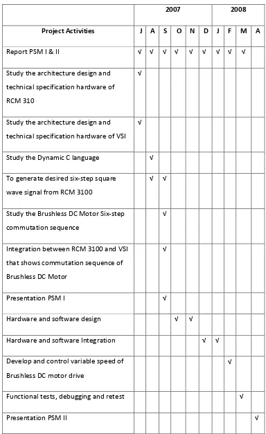
1.4 Project Planning Schedule (Gantt chart)
2007 2008
Project Activities J A S O N D J F M A
Report PSM I & II √ √ √ √ √ √ √ √ √
Study the architecture design and technical specification hardware of RCM 310
√
Study the architecture design and technical specification hardware of VSI
√
Study the Dynamic C language √ To generate desired six-step square
wave signal from RCM 3100
√ √
Study the Brushless DC Motor Six-step commutation sequence
√
Integration between RCM 3100 and VSI that shows commutation sequence of Brushless DC Motor
√
Presentation PSM I √
Hardware and software design √ √
Hardware and software Integration √ √ Develop and control variable speed of
Brushless DC motor drive
√
Functional tests, debugging and retest √
[image:21.595.91.475.69.696.2]Presentation PSM II √
CHAPTER 2
LITERATURE REVIEW
2.1 Embedded Controller and Embedded System
Microprocessors in embedded systems are typically optimized to perform a single task, often a control application. The design of these embedded systems requires a consideration of limiting factors such as small memory, slow processing speed, and limited electrical power that are rarely addressed in general-purpose computers. Microprocessor support for Embedded Systems applications must include interfacing the microprocessor with the user and other devices. In addition to direct pin-by-pin port I/O, protocols such as RS-232, SPI, IIC, and CAN are widely supported. Embedded Systems are often used for real world control so analog-to-digital and digital-to-analog conversions and their implications, such as the Nyquist criterion, need to be emphasized. Similarly, for many control applications, timing is critical so the ability to use event timers, watchdog timers, and related applications such as PWM are important. [1]
system prototype uses 5.7K bytes of program memory, 854K bytes of internal data memory and 2M bytes external DRAM.[2]
The methods and experiences of developing software and toolkit flows for PAC (Parallel Architecture Core) VLIW DSP processors. Parallel Architecture Core (PAC) is a five-way VLIW DSP processor with distributed register cluster files and multi-bank register architectures (known as ping-pong architectures. Our toolkits include compilers, assemblers, debugger, and DSP micro-kernels. We first retarget Open Research Compiler (ORC) and toolkit chains for PAC VLIW DSP processor and address the issues to support distributed register files and ping-pong data paths for embedded VLIW DSP processors. We also deploy software pipelining techniques with the considerations of distributed register file architectures. The linker and assembler of our toolkits are able to support variable length encoding schemes for DSP instructions. In addition, the debuggers were designed to handle dual-core environments. The debugger is also integrated with Eclipse IDE. The footprint of micro-kernel is also around 10K to address the code-size issues for embedded devices. [3]
2.1.1 Microprocessor
A microprocessor is a programmable digital electronic component that incorporates the functions of a central processing unit (CPU) on a single semiconducting integrated circuit (IC).
computing". First, microprocessors opened up a new "era of programming" through replacing with software, the hardwired logic based on IC's of the former "era of logic". At the same time, microprocessors allowed young engineers access to "power of computing" for the creative development of personal computers and computer games, which in turn led to growth in the software industry, and paved the way to the development of high-performance microprocessors. In 20th century, microprocessors were used for increasing "power of intelligence". In 21st century, microprocessors will evolve into "tool to bring forth wisdom" for all mankind. [4]
Today, microprocessors for personal computers get widespread
atte tio a d ha e e a led I tel to e o e the o ld s la gest
semiconductor maker. In addition, embedded microprocessors are at the heart of a diverse range of devices that have become staples of consumers worldwide. Microprocessors have become specialized in many ways. The desktop computer market tends to discard old processors in just a few years, many processors survive for an amazingly long time in the embedded market. Personal computers have moved from 8-bit to 16-bit and now to 32-bit processors and many workstations and servers are already using 64-bit microprocessors. Microprocessors for personal computers get the most public attention because the performance and compatibility of PCs depend on the microprocessors at their cores. [5]
i. 8-bit Microprocessor