Abstrak
Penelitian ini merupakan penelitian lanjutan mengenai kuat tarik sambungan komposit Glugu-Bangkirai yang dilakukan oleh Awaludin & Triwiyono (2003). Hal baru yang dilakukan pada penelitian ini adalah penggunaan cincin belah sebagai alat sambung, sedangkan pada penelitian sebelumnya (Awaludin & Triwiyono, 2003), alat sambung yang digunakan adalah dua baut 15.6 mm (5/8 inchi). Selain kuat tarik sambungan hasil pengujian, kuat tarik sambungan juga dianalisis dengan persamaan dari Euro Code 5 dan Awaludin & Triwiyono (2002). Diameter dan panjang cicin belah yang dipergunakan berturut-turut adalah 40 mm dan 30 mm, sedangkan diameter baut pengaku adalah 12.5 mm (½ inchi). Pada setiap sambungan terdapat dua cincin belah sebagai alat sambungnya.
Hasil penelitian menunjukkan bahwa, kuat tarik sambungan dengan alat sambung cincin belah lebih tinggi 30% dari pada kuat tarik sambungan dengan alat sambung baut. Sesaran pada sambungan dengan alat sambung cincin belah lebih kecil yaitu 67% dari pada sesaran sambungan dengan alat sambung baut. Kuat tarik ultimit sambungan hasil pengujian tersebar disekitar kuat tarik ultimit dari Euro Code 5 dan Awaludin & Triwiyono (2002).
Kata-kata kunci : cincin belah, kuat tarik, sesaran.
Abstract
This research was a further research on tensile load of three-member connection of Coconut and Bangkirai lum-ber (Awaludin & Triwiyono, 2003). The new thing done in this experiment is the use of split ring as the connec-tor of the connection. In the previous research (Awaludin & Triwiyono, 2003), two bolts of 15.6 mm were used as the connectors in each connection. Besides the result from experiment, the ultimate tensile load of split ring connection was also analyzed with equations from Euro Code 5 and Awaludin & Triwiyono (2002). The dimen-sion of split-ring connector was 40 mm in diameter, 30 mm in length, and bolt of 12.5 mm was used to tight the connection. Two split ring connectors were placed in every connection. The result shows that the ultimate tensile load of split-ring connection was thirty percent higher than the bolted connection. The displacement of split ring connection was only 67% of the displacement of bolted connection. The ultimate tensile load of experiment was scattered closely to the result of Euro Code 5 and Awaludin & Triwiyono (2002).
Keywords : split ring, tensile load, and displacement.
Split Ring Connection of Coconut and Bangkirai Lumber
Ali Awaludin1)
TEKNIK
SIPIL
1. Introduction
1.1 Background
Wood is extensively used for construction especially in rural area where timber can be quite easy to get. Wood is used in truss structures such as roof and bridge besides frame and floor system. Some advan-tages that would be obtained when wood is used in construction compared with the other materials are: first is the total weight of construction would be smaller, and second is the simplicity in fabrication.
woods of high grade, middle grade, and low grade can be used optimally and wisely to conserve wood sustainability.
Bolt has been used in wood joint or connection since long time ago. Bolt is one of the mechanical connector where the connection strength is determined by the bending strength of bolt and the bearing or shear stress of wood. Joint in wood structure is known as the weakest part. The increase in connection strength will give significant benefit to whole structure. Many research have done to find out wood jointing methods and wood connectors.
In the previous research, Awaludin & Triwiyono (2002), three-member connection of Coconut and Bangkirai lumber were tested in several angles of load to grain. Two bolts of 15.6 mm (5/8 inchi) were used as the connectors. Because the need to increase the tensile load and to decrease the displacement, split ring will be used in this experiment. In addition to that, the ultimate tensile load of connection of experiment also will be evaluated with some theoretical formulae.
2. Objectives
The objectives of this research were:
1. to find out the load-slip curve of three-member connection of Coconut and Bangkirai lumber with split ring connector,
2. to find out the advantage of using split ring connectors compared with bolt connector in three-member connection of Coconut and Bangkirai lumber, and
3. to evaluate the ultimate tensile load of split ring connection with some theoretical formula.
3. Literature Cited
Because wood is a natural resource, the structural properties of wood vary from one species to another species and even in one trunk: the bottom, the middle, and the upper part. Two things that are potentially controlled the strength of wood are moisture content and density or specific gravity. Water exists in wood in two ways: in the cell cavities as free water and in the cell wall as bound water. There are three common conditions in describing water content in wood: green water, fiber saturation point, and air-dry condition. For structural purposes, it is recommended to use lumber at air-dry condition (the water content is about 12 to 15%). The strength of wood increases as the water content decreases. But the water content decrease should be made gradually to avoid crack or split. Density can be used to predict the strength of a specific wood. Wood with high density will also have high strength grade.
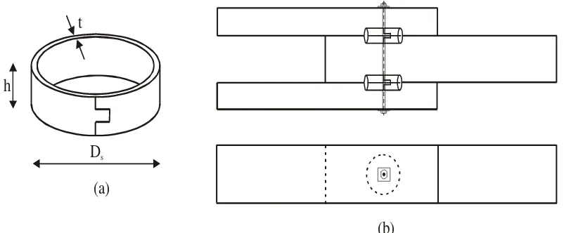
Ring (split ring) is used laterally loaded timber to tim-ber connection and generally in combination with bolt (see Figure 1). Ring is available in a variety of shape and size. The common shape of ring are double bevel and flat, and the common size are 2½ inchi (64 mm) and 4 inchi (100 mm). Diameter of bolt which is used in 2½ inchi and 4 inchi ring are ½ inchi and ¾ inchi respectively. This bolt is used to tight the connection so that the ring connector worked optimally. Accord-ing to Blass in Blass et al (1995), rAccord-ings are always circular because they are placed into precut grooves produced by rotary cutters and are made from alumi-num cast alloy, steel or cast iron.
D
sh
t
(a)
(b)
The tensile load of split ring connection is determined not only by the diameter and the length of ring, but also the water content of members as shown in Figure 2. Tensile load of double bevel ring is higher than that of the flat ring, while the displacement of double bevel ring is smaller than that of flat ring. The failure mode of ring connection can be studied in Figure 2. Accord-ing to Faherty (in ASCE, 1996), at the proportional limit, wood between the ring and bolt begin to crush, then followed by the bent of bolt. After that, the final failure of wood splitting parallel to grain occurs until its ultimate tensile load. Beyond the proportional limit, depending on the thickness of the members, wood splitting may occur rather abruptly (in thin member) or additional compression of wood fiber takes place and the bolt begins to bend (thick member).
Euro Code 5 in Blass et al (1995) introduce Equation 1 and Equation 2 to analyze the tensile load of split ring connection (Psr). The least value of these two equation is used as the design value. The tensile load which is sustained by the bolt is neglected. These equations give good prediction at 13% of water content. Equa-tion 3 is used to obtained tensile load of split ring connection when the load direction to grain is not parallel.
Water content at time of test approximately 13% 4-inchi-Double bevel
Split-ring connectors
4-inchi-Flat
Split-ring connectors First drop
Figure 2. Load-slip curve of 4 inchi split-ring connections at 13% and 32% water content
According to Awaludin & Triwiyono (2002), the ulti-mate tensile load of split ring connection is the total tensile load that is developed by the ring and the bolt. The tensile load that is developed by the ring is a com-bination between shear and compression strength. Equation 4 is recommended formula by Awaludin & Triwiyono (2002) to obtain the ultimate tensile load of split ring connection. Tensile load which is developed by bolt (Pb) is similar to the nominal strength of bolt
(Z).
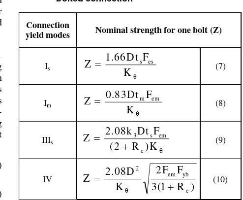
The nominal strength for one bolt (Z) of three-member connection is the least value which is obtained from Equation 5 to Equation 8 in Table 1. Yield mode in Table 1 de-scribes the failure mode of bolted connection. The yield modes Is and Im are the result of wood fiber
crushing in side member and main member respec-tively. Yield mode IIIs is the result of bolt yielding
with one plastic hinge at the shear plane along with the wood fiber crushing in side member. Yield mode IV is the result of bolt yielding in many plastic hinges.
75
Nominal strength for one bolt (Z)
θ
4. Material
Twelve three-member connections of Coconut and Bangkirai lumber were made in this research. The side members of connection were two Coconut lumber of 40/150 mm2, and the main member was one Bangkirai lumber of 60/150 mm2. The angle of load to grain is varied into 90°, 60°, 45°, and 0° (parallel) to side members. Two split rings of 40 mm in diameter, 30 mm in length and two bolts of 12.5 mm (½ inchi) in diameter were used in every connection.
Preliminary tests such as water content test, dowel bearing strength, and mechanical properties of Coco-nut and Bangkirai lumber were conducted. Drying process is also conducted to obtained air-dry lumber. The connection specimens were tested until its ulti-mate tensile load. Failure mode and displacement were also observed to obtain load-slip curve of connection.
5. Result and Discussion
Three-member connections were assembled and tested in air-dry condition. The water content at time of test of Coconut and Bangkirai lumber were 15.86% and 17.95% respectively. The result of tensile test which is presented in load-slip curve showed that: The load-slip curve of split-ring connection is steeper than that of bolted connection, and the ultimate tensile load of split ring connection was higher than that of bolted connec-tion especially when the angles of load to grain were 45° and 60°. The average ratio between the ultimate tensile load of split ring connection to the ultimate tensile load of bolted connection (Psr/Pb) was 1.30 as shown in Table 2. Furthermore, the displacement of split ring connection was smaller than the displace-ment of bolted connection. For instance, when the tensile load was parallel to grain, the displacement of split ring connection was only 67% of the displace-ment of bolted connection. The yield mode of connec-tion was initiated by the crush of wood between ring and bolt, followed by the bent of bolt until the ultimate tensile load. The deformation on ring connectors was observed after the connections were dismantled. There
2
is no significant deformation on ring connectors. But all ring connectors and bolts became so rusty around the Coconut lumber (side members).
The ultimate tensile load of split ring connection can be evaluated with Equation 1 to Equation 3 of Euro Code 5 and Equation 4 to Equation 6 of Awaludin & Triwiyono (2002). Data from experiment which were used to evaluate the ultimate tensile load of connection were listed below. Density (ρ) of Coconut lumber was taken from Morisco et al (1998). Bending strength of bolt was taken 320 N/mm2 as it is suggested by National Design and Specification (NDS) of USA for timber construction (ASCE, 1996). The ultimate tensile load of split ring connection which was evaluated with Euro Code 5 was presented in Table 4.
Angle of
Table 2. Ultimate tensile load of connection
Bolted
Table 3. Maximum slip of connection with tensile loaded parallel to grain
Angle of
Table 4. Ultimate tensile load connection according to Euro Code 5
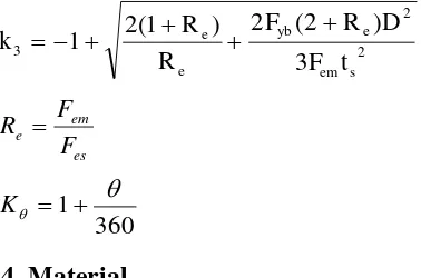
The failure mode of split ring connection was a combi-nation between the strength of bolt, the shear strength and dowel bearing strength of wood around the ring. Since the shear strength of Coconut lumber was lower than its dowel bearing strength, so the strength reduc-tion factor (λs) will be equal to one and the
compres-sive strength reduction factor (λc) will lay between nil
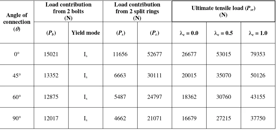
to one. Some modification was made to Equation 5 and Equation 6. This modification was written in Equation 11 to Equation 14. The ultimate tensile load of split ring connection was obtained from Equation 4 and step by step described in Table 5. The compres-sive reduction factors of 0, 0.5, and 1.0 were applied to analyze the ultimate tensile load, while the shear strength reduction factor was 1.0.
(11)
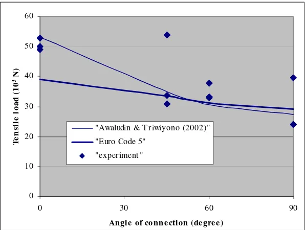
The ultimate tensile load of Awaludin & Triwiyono (2002) with λc=0.5, of experiment, and of Euro Code 5
were plotted in Figure 3. It can be seen in Figure 3 that the ultimate tensile load of experiment were scattered closely to both Euro Code 5 and Awaludin & Triwiyono (2002) curves, except for one data of 45° of connection angle. The ultimate tensile load curve of Euro Code 5 intersects with the curve of Awaludin & Triwiyono (2002) in connection angle from 45° to 60°. The ultimate tensile load of Euro Code 5 at connection angle below 45° was lower than that of Awaludin & Triwiyono (2002). While at connection angle from 60° to 90°, the ultimate tensile load of Euro Code 5 was higher than that of Awaludin & Triwoyono (2002). For analysis, equation of Euro Code 5 can be used instead of that of Awaludin & Triwiyono (2002).
Two questions arise in the equation which was suggested by Awaludin & Triwoyono (2002) are: (1). the value of compressive reduction factor (λc) will be equal to 0.5 or will be not if the size of split-ring changes, and (2). If the diameter of bolt higher than 12.5 mm, will the ultimate tensile strength of connec-tion increases?. To answer these quesconnec-tions, future research on split ring connection which various value of diameter, length of split ring connector, and diameter of bolt should be conducted.
Table 5. Ultimate tensile load connection according to Awaludin & Triwiyono (2002)
Load contribution from 2 bolts
(N)
0 10 20 30 40 50 60
0 30 60 90
Angle of conn e ction (de gre e )
T
e
n
sil
e
lo
a
d
(
1
0
3 N)
"Awaludin & T riwiyono (2002)"
"Euro Code 5"
"experiment "
Figure 3. Ultimate tensile load of connection; Experiment and Theoretic
6. Conclusion
1. The load-slip curve of split-ring connection is steeper than the load-slip curve of bolted connec-tion.
2. The ultimate tensile load of split-ring connection was 30% higher than the bolted connection.
3. The displacement of split ring connection was only 67% of the displacement of bolted connection.
4. The ultimate tensile load of experiment was scat-tered closely to the result of Euro Code 5 and Awaludin & Triwiyono (2002).
References
American Society of Civil Engineers, 1996, “Mechanical Connections in Wood Structures’. New York.
Awaludin, A., and Triwiyono, A., 2002, “Penggunaan Komposit Coconut-Bangkirai Pada Struktur Truss”. One-day Seminar on Hasil Penelitian Bidang Rekayasa Teknik Dosen UGM dan Per-guruan Tinggi DIY & Jawa Tengah Tahun 2002. Engineering Faculty of Gadjah Mada University. Yogyakarta.
Awaludin, A., and Triwiyono, A., 2003, “Ultimate Tensile Load of Three-Member Bolted Connec-tion”, Media Teknik of Engineering Faculty of Gadjah Mada University, February 2003. Yogyakarta.
Badan Akreditasi Nasional, 2002, “Tata Cara Peren-canaan Konstruksi Kayu Indonesia (PKKI-NI-5)”, Jakarta.
Blass, H.J., Aune, P., Choo, B.S., Gorlacher, R., Grif-fiths, D.R., Hilson, B.O., Racher, P., Steck, P., 1995, Timber Engineering STEP 1. Centrum Hout. The Netherlands.
Morisco, Triwiyono, A, Mardjono, F., 1998, Perilaku Mekanik Kayu Glugu, Research Report at Engi-neering Faculty of Gadjah Mada University. Yogyakarta.
Notation
ts = width of side member (mm)
tm = width of main member (mm)
D = diameter of bolt (mm)
Ds = diameter of split-ring connector (mm)
a = end distance of split-ring connection (mm)
ρ = wood density (kg/m3)
λs = shear strength reduction factor
λc = compression strength reduction factor
θ = angle of load to grain
Pb = Z = nominal strength of bolt (N)
Ps = shear strength of split ring connection (N)
Pc = compressive strength of split ring connection (Ν)
Psr = ultimate tensile load of split-ring connection
Fes = dowel bearing of side member (N/mm2)
Fem = dowel bearing of main member (N/mm2)