MEASUREMENT TECHNIQUE OF REYNOLDS NUMBER USING
CYLINDRICAL TUBE AND COLORED FLUID INJECTION
Oleh :
Agustin Eka Budhi Rahayu NIM : 192012021
TUGAS AKHIR
Diajukan Kepada Program Studi Pendidikan Fisika, Fakultas Sains dan Matematika
guna memenuhi sebagian dari persyaratan untuk memperoleh gelar Sarjana Pendidikan Program Studi Pendidikan Fisika
FAKULTAS SAINS DAN MATEMATIKA
UNIVERSITAS KRISTEN SATYA WACANA SALATIGA
MOTTO
Boleh jadi kamu membenci sesuatu, padahal ia amat baik bagimu, dan boleh jadi (pula) kamu
menyukai sesuatu, padahal ia amat buruk bagimu, Allah mengetahui,
sedang kamu tidak mengetahui.
(Q.S Al-Baqarah 216)
Sesungguhnya sesudah kesulitan itu ada kemudahan. Maka apabila kamu telah selesai (dari
suatu urusan), kerjakanlah dengan sungguh-sungguh (urusan) yang lain.
KATA PENGANTAR
Segala puji dan syukur penulis panjatkan kepada Allah SWT dan junjungan Nabi besar Agung Muhammad SAW karena karunia-Nya penulis dapat menyelesaikan tugas akhir dengan
judul “Measurement Technique Of Reynolds Number Using Cylindrical Tube And Colored
Fluid Injection”, telah dipublikasikan dalam Seminar “The 2nd IConSSE Fakultas Sains dan Matematika, Universitas Kristen Satya Wacana pada tanggal 30-31 Agustus 2017 di Universitas Kristen Satya Wacana Salatiga.
Laporan penelitian ini disusun untuk tugas akhir dan sebagai salah satu syarat untuk menyelesaikan pendidikan di Program Sarjana Pendidikan di bidang pendidikan fisika Universitas Kristen Satya Wacana serta untuk memenuhi persyaratan memperoleh gelar Sarjana Pendidikan.
Dalam penulisan ini penulis merasa tidak berjalan sendiri dalam menjalani segala proses penyusunan skripsi. Ada orang-orang hebat yang selalu ada untuk penulis. Oleh karena itu, dengan
kerendahan dan ketulusan hati penulis ingin menyampaikan rasa terima kasih kepada pihak–pihak
yang menjadi bagian dalam memberikan semangat, motivasi, ketenangan, kekuatan serta bimbingan baik selama penulis menyelesaikan tugas akhir ini, maupun selama menempuh pendidikan di Universitas Kristen Satya Wacana.
1.
Allah SWT yang telah melimpahkan Rahmat dan Karunia-Nya sehingga terleselainyaSkripsi.
2.
Dr. Suryasatriya Trihandaru, M.Sc.nat selaku pembimbing utama yang dengan sabarmembimbing, mengarahkan dan memberikan motivasi kepada penulis selama proses penulisan skripsi ini sehingga laporan skripsi ini dapat diselesaikan dengan baik.
3.
Dra. Marmi Sudarmi M.Si, M.Sc selaku pembimbing/pendamping yang jugamembimbing, memberikan saran, dan mengarahkan penulis sehingga laporan skripsi ini dapat diselesaikan dengan baik.
4.
Dosen pengajar, Made Rai Suci Shanti Nurani Ayub, S.Si, M.Pd, Diane Noviandini,S.Pd., M.Pd, Prof. Dr. Ferdy Semuel Rondonuwu, M.Sc., dr. Jodelin Muninggar , Adita Sutresno, S.Si., M.Sc, Nur Aji Wibowo, S.Si., M.Si, Debora Natalia Sudjito, S.Pd., M.Ps.Ed, Giner Maslebu, S.Pd., S.Si., M.Si dan Alvama Pattiserlihun, S.Si., M.Ed yang telah memberikan ilmu pengetahuan kepada penulis selama studi di FSM UKSW.
5.
Seluruh staf TU FSM dan Laboran, Mas tri, Mas sigit, Pak Taufip yang telah banyakmemberikan bantuan kepada penulis dan membantu selama penggunaan alat-alat lab fisika.
6.
Bapak dan Ibu yang telah menjadi pahlawan doa dan penyumbang materi bagi penulisserta memberikan kasih sayang yang terbaik. Terima kasih telah memberikan kesempatan untuk penulis mengenyam pendidikan, memenuhi kebutuhan, memberikan arahan dan semangat setiap kali penulis merasa berat menjalani seluruh proses ini.
7.
Saudara tercintaku Aprilia Arum. Terima kasih atas dorongan dan doanya untuk8.
Angkatan terbaikku, Physics and physics education 2012, kalian sudah menjadi sahabat serta saudara selama 4 tahun ini. Banyak kisah yang takkan pernah bisa tergantikan.9.
Terima kasih kepada mas pacar telah membantu kelancaran skripsi.10.
Sahabat-sahabat tebaikku, Muntamah, Widad, Ella, Amy, Rizky terima kasih buatsenyuman-senyuman yang kalian berikan. Sukses buat kuliah dan perjuangan skripsi
kalian. Tetap semangat untuk kita semua, kita akan bertemu dalam sebuah kesuksesan.
11.
Keluarga 1000 GURU SOLO. Selalu menyemangati dan memotivasi agar segeramenyelesaikan Skripsi.
12.
Dan keluaraga besar serta pihak-pihak yang tidak dapat penulis sebutkan satu per satu, terimakasih untuk dukungan dan doanya kepada penulis.Penulis menyadari sepenuhnya bahwa dalam penulisan skripsi ini masih terdapat banyak kekurangan dan jauh dari kesempurnaan. Oleh karena itu, penulis sangat mengharapkan segala saran dan nasihat dari pembaca. Harapan penulis, semoga skripsi ini bermanfaat bagi semua pihak.
Salatiga, 18 September 2017
Penulis
DAFTAR ISI
HALAMAN JUDUL... i
LEMBAR PENGESAHAN... ii
LEMBAR PERNYATAAN KEASLIAN... iii
LEMBAR PERSETUJUAN AKSES... iv
MOTTO... v
KATA PENGANTAR... vi
DAFTAR ISI... vii
ABSTRAK... 1
PENDAHULUAN ... 2
METODE... 5
HASIL DAN PEMBAHASAN ... 6
KESIMPULAN ... 9
DAFTAR PUSTAKA... 10
LAMPIRAN
1
MEASUREMENT TECHNIQUE OF REYNOLDS NUMBER USING
CYLINDRICAL TUBE AND COLORED FLUID INJECTION
Agustin E. B. Rahayu *, Marmi Sudarmi, Suryasatriya Trihandaru **
Physics Department, Faculty of Science and Mathematics, Satya Wacana Christian University,
Diponegoro St. No. 56-60, Salatiga 50711 Indonesia *[email protected]
**Corresponding Author: [email protected]
ABSTRACT
In this paper we give the result of the study of several types of flow of liquid in the vertical cylindrical tube, those are divided into three kinds of flow ; laminar, transitional, and turbulent flow, depending on the Reynolds number (Re). The fluid flow in the cylindrical tube is studied by adding colored dilute liquid in the middle-top of the cylindrical such that it shows a thin track of colored fluid inside the fluid flow. The laminar, transitional or turbulent flow can be realized by controlling the faucet aperture that gives different values of Reynolds numbers. The flow is captured by the Kodak digital camera Easyshare M863 8.2 mega pixel. Reynolds numbers are obtained by measuring its volumetric flow rate divided by the cross-sectional area of the tube. The fluid flow images as indicate that a stream with a Reynolds number less than 2000 appears as a laminar flow, between 2000-4000 as a transitional stream, and above 4000 as turbulent flow.
Keywords: laminar, Reynolds number, transition, turbulent
*
3
The purpose of this research is to visualize fluid flow with various Reynolds values, to measure the Reynolds number of fluid flow in the vertical pipe, and to find the limit of Reynolds value which still shows the laminar flow.
Theoretical Basis
The fluid flow with constant density
and constant viscosity
satisfy the Naiver Stokes equation as follows (F. M. White, 1999):2 Equation can be written by:
2 2
Eq. (2) is a general fluid mobility equation whose solution cannot be derived analytically so that it must use the numerical methods. However, for a simple flow that is the flow of fluid laminar in a pipe or so-called Poiseuille flow, the solution can be derived analytically. Poiseuille flow is derived from Naiver Stokes equation assuming that its flow is laminar in long enough pipe, so the variation of velocity on
z
axis can be ignored as follows:4
Thus, the Naiver Stokes equation assuming (3), (4), (5) and (6) becomes:
(7)
In Eq. (7), the unit of measurement for each variable is as follows. Variable
t
in seconds,r
in meters,p
in Pascal,
in Ns/m2 and
in kg/m3. To show the important parameters in Eq. (7), a non-dimensionalized method is required. The trick is to introduce the dimensionless variables as in Table 1. (Peixinho, J., Nouar, C., Desaubry, C. & Theron, B. 2005 )and (L. I. Sedov. 1959):Table 1. The dimensionless variables
Variable Unit Dimensionless Variable Note
t
secondBy including the dimensionless variable in Table 1. the equation becomes
* * *
In Eq. (8) has been collected important parameters as the multiplier factor of the both on the right side. This factor will determine the flow profile, which is referred to as Reynolds number (Re) (1883) which is defined as follows:
5
Re is the Reynolds number, vref is the speed of reference,
v
is the measured velocity, D is the diameter,
is the density of the substance,
is the dynamic viscosity, and
is the kinematic viscosity. It is further assumed that the fluid flow has reached a steady state so that the velocity derivative over time is zero. Thus obtained Poiseuille equation*
Which has the following solutions:
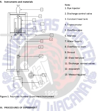
2 instrument as in Figure. 1.
Dye Injector
6
The working principle of the instrument is the measurement of fluid flow discharge in the transparent pipe by dividing the volume of fluid in the measuring glass against time. In this modeled instrument, (1) a color injector is used to provide color to the flowing fluid in order to show fluid flow patterns, in which the color injector is provided with an opening valve to drain the dye to the fluid, (2) a thermometer for measuring The fluid temperature in the tank, (3) the tank which is used as fluid shelter, which has 3 holes for the inlet of the fluid inlet pipe, for the transparent pipe port, and the fluid output, (4) the marbles in the tank are used for removing the water ripple, (5) transparent pipes used for visualizing fluid flow, the tube is provided with a valve, (6) a 0.2 liter measuring glass is used for volume measurement. The instrument used has the following specifications: tank maximum volume is 15 liters, transparent pipe diameter is 2. 92x10-2 m, transparent pipe length is 0.8 m, and has a stop valve with 3. 81x 10-2 m in diameter.
The measurement experimental steps of the Reynolds number are as follows. First was performed by measuring the discharge with the Eq. (12):
=
V
Q
t
(12)From Eq. (12)
Q
is the fluid discharge, V is the fluid volume measured by the measuring glass,t
is the fluid flow time. After obtaining the value of the discharge then calculated the velocity of the fluid through the equation:
v
Q
A
(13)From Eq. (13), A is the transparent cross-sectional area. By the obtained value of
v
, the magnitude of the Reynolds number can be calculated by Eq. (9). Thisv
value is used as thereferred velocity in Eq. (9).
Visualization of fluid flow was obtained by photographs when the fluid is flowing through the transparent pipe using Kodak Easyshare M863 8.2 mega pixel digital camera. In this study, the final results of the experiments are attached by the experimental module of the Reynolds number experiments.
2. Results and Discussion
7 3.
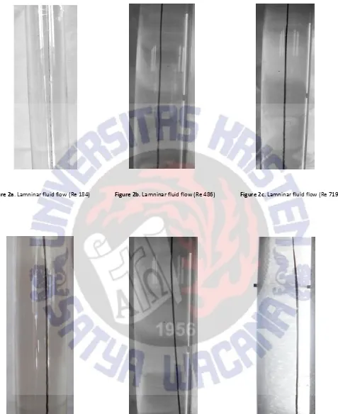
Figure 2a. Lamninar fluid flow (Re 184) Figure 2b. Lamninar fluid flow (Re 486) Figure 2c. Lamninar fluid flow (Re 719)
8
Figure 2a -2f. shows the visualization of the laminar fluid flow. The flow is characterized by a steady state in which all flow lines follow a relatively straight path without any movement of turn or curl. In the fluid flow observation, the factors that affect the fluid flow velocity (and the Reynolds number) are the width of valve hole (stop faucet) on the color injector and also the valve underneath the transparent pipe.
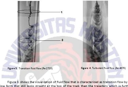
Figure 3. shows the visualization of fluid flow that is characterized as transition flow by its flow form that still looks straight at the top of the track then the trajectory which is further characterized by the irregularity that occurs in the path trajectory. The transition flow is a transition from the laminar flow to the turbulent flow.
Figure 4. shows the turbulent fluid flow. The flow is characterized by its flow that resembles a swirling vortex and intermittent flow line causing a broken flow pattern and a mixing of fluid with dye occurs (in this case, the dye dissipates when the fluid mixing is taking place).
Figure 3. and Figure 4. do not show laminar flow, this can be explained theoretically because the used assumptions in the equations in laminar flow are not met, i.e. (1) the angular velocity turns out to vary in the
z
axis (at points 1 and 2 in Fig. 3, thev
must be different, indicated by the motion of the dye), (2) the pressure varies onr
and
that shown by the dispersed dye.9
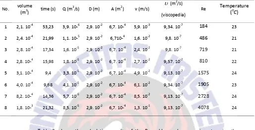
The data result of the Reynolds number experiment are shown in Table 2.
Table 2. Calculation results from Reynolds number experiments Reynolds number data value
No. volume modeled instrument. The laminar flow calculation is shown in Table 2. by the 1st to 6th with the values of each Reynolds number obtained under 2000 that match to the Reynolds value limit which shows the laminar flow and is shown before in Figures 2a to 2f. The Reynolds number at 7th is between 2000 to 4000 that shows the transition flow and shown in Figure 3. While at 8th the Reynolds number is over 4000 that indicates the turbulent flow and shown in Figure 4.
4. Conclusion and Remarks
10
References
B. R. Munson, D.F Young and T. H. Okiisshi, 1998. Fundamentals of Fluid Mechanics, John Wiley and Sons, Inc. .
F. M. White, 1999. Fluid Mechanics, McGraw-Hill.
L. I. Sedov. 1959. Similarity and Dimensional Methods in Mechanics,Academic, New York.
Moin, P. & Kim, J. 1982. Numerical Investigation of Turbulent Channel Flow. Journal of Fluid Mechanics,
118, 341-377.
Multigrid Navier-Stokes Calculations for Three-Dimensional Cascades
http://aero-comlab.stanford.edu/Papers/AIAA-11850-730.pdf
Orianto, M. Ir. BSE dan Pratikto, W.A. Ir. M. Sc. 1995. Mekanika Fluida 1, BPFE:Yogyakarta
Peixinho, J., Nouar, C., Desaubry, C. & Theron, B. 2005. Laminar transitional and turbulent flow of yield stress fluid in a pipe. Journal of Non-Newtonian Fluid Mechanics, 128, 172-184.
Reynolds, O. 1883. An experimental investigation of the circumstances which determine whether the motion of water shall be direct or sinous, and of the law of resistances in parallel channels. Phil Trans Roy Soc London, 174, 935-982.
Reynolds, O. 1895. On the Dynamical theory of Incompressible Viscous Fluids and the Determination of the Criterion. Phil. Trans. Roy. Soc. (London), 186A, 123-164.
Ridwan. (1982). Mekanika Fluida, Universitas Gunadarma, Depok.
Salwen, H., Cotten, F. W. & Grosch, C. E. 1980. Linear stability of Poiseuille flow in a circular pipe. J. Fluid Mech., 98, 273.
Tutorial on Scaling Analysis of Navier-Stokes Equations: Linear and Non-linear Dynamics of Fluid-Structure-Interaction
https://www.asdjournal.org/index.php/asd/article/viewfile/15/dowell_asdj2011.pdf
11
12
EXPERIMENT MODULE
I. Purpose
Visualize the laminar flow and calculate the Reynolds number.
II. Instruments and materials
11. Discharge control valves 12. stopwatch
13. Measuring glass
Figure 1. Reynolds Number Experiment Instrument
III. PROCEDURES OF EXPERIMENT
a. Prepare the experimental instruments by placing the Reynolds number experiments according to Figure 1.Reynolds number experimental instrument.
b. Fill the Reservoir (1) with the dye (ink), and lower the dye injector until it reaches the upper inlet mouth.
c. Open the inflator valve on water supply (7) and let the liquid enter the tank. Try to achieve a constant fluid surface, do not exceed
d. Leave the fluid for 5 minutes and measure the fluid temperature by putting the thermometer into it (4).
e. Open the flow control valve (2) gradually and arrange the dye-controlling valve until it reaches the slow flow with clear dye.
13
f. Determine the magnitude of the discharge
Q
by accommodating the flowing liquid through the tube during certain time into the measuring glass.g. Enter the obtained discharge
Q
into Table. 1, then calculate the Reynolds number value.h. Take a picture of the flowing fluid through the transparent tube (10) while the measurement of the discharge value taking place.
i. At each end of the experiment, measure the temperature again.
j. Repeat the procedure above for varying
Q
from small magnitude until each laminar, transition and turbulent fluid flow is achieved.14