Load Current Control for Three-Phase Power
Converter SVPWM with Current-Regulation
Hari Sutiksno
*, Maurice Fadel
**1,2, Yanuarsyah Haroen
***, Mochamad Ashari
****and Mauridhi Hery P
**** * Sekolah Tinggi Teknik Surabaya (STTS), Surabaya, Indonesia**1 Université de Toulouse ; UPS, INPT ; LAPLACE (Laboratoire Plasma et Conversion d’Energie) ,France **2 CNRS ; LAPLACE ; F-31062 Toulouse, France
*** Institute of Technology Bandung, School of Electrical Engineering and Informatics, Bandung, Indonesia **** Institut Teknologi Sepuluh Nopember (ITS), Surabaya, Indonesia
Abstract — This paper presents a new method to improve the DC voltage response on the load change of a three-phase power converter space vector PWM with current regulator. The line current reference is generated from the load current referred to as control-side and the output of PI controller driven by DC voltage error. The load current estimation can be obtained by using the Luenberger observer. A simplified model of converter with its current regulator has also been proposed. The simulation results indicate that the proposed method can produce good dynamic behavior of the DC voltage and unity power-factor of the line currents.
Keywords — Converter control, modeling, pulse width modulation (PWM)
I. INTRODUCTION
Due to the low harmonic distortion, high efficiency and bidirectional power flow, the space vector Pulse Width Modulation (PWM) remains a popular technique used in three-phase power converters [1-5]. The space vector PWM current regulator generates a reference vector in such a way that the amplitude and the phase-difference of the line current can be driven to a reference value [6]. Although the PI controller is commonly used to control in a three-phase power converter, the DC voltage response with respect to the load change is somewhat poor. This paper proposes a new load current control method to improve the DC voltage response of a three-phase power converter space vector PWM using current regulation method. In this case, the load current is estimated using the Luenberger observer [7]. In order to reduce the ripples and the complexity of the algorithm, a simplified model of converter and its current regulator has been used.
II. MATHEMATICAL MODEL OF THREE-PHASE POWER CONVERTER SVPWMWITH CURRENT REGULATOR
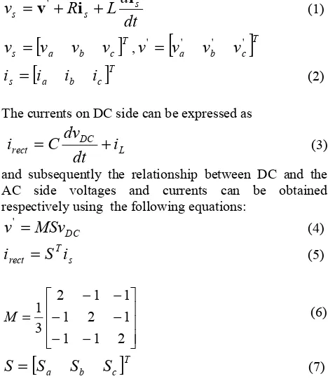
[image:1.595.305.539.256.528.2]Three-Phase Power Converter Equation
Fig 1 shows the typical circuit diagram of a three-phase power converter. The currents and voltages on the AC side can be expressed using the following equation
dt
d
L
R
v
s s si
i
v
+
+
=
' (1)[
]
Tc b a
s
v
v
v
v
=
,v
'=
[
v
a'v
b'v
c']
T[
]
Tc b a
s
i
i
i
i
=
(2)The currents on DC side can be expressed as
L DC rect
i
dt
dv
C
i
=
+
(3)and subsequently the relationship between DC and the AC side voltages and currents can be obtained respectively using the following equations:
DC
MSv
v
'=
(4)s T rect
S
i
i
=
(5)⎥ ⎥ ⎥ ⎦ ⎤ ⎢ ⎢ ⎢ ⎣ ⎡ − − − − − − = 2 1 1 1 2 1 1 1 2 3 1
M (6)
[
]
Tc b
a
S
S
S
S
=
(7) [image:1.595.306.527.569.695.2]In (7), S=1 when the switch is on, and S=0 when the switch is off.
Fig. 1. Three-phase Power Converter
Space Vector PWM Current Regulator
Current regulator is used to generate the reference space vector voltage such that the average line current over the period Ts for next period is in phase to the voltage of the
power source. This can be mathematically written as Va L
Vb L
Vc L
Sa S b Sc
S'a S'b S'c
C +
_ RLL
ia ib ic Irect iC IL VDC N V’a V’b V’c
i
s(
t
+
T
s)
=
kv
s(
t
+
T
s)
(8)By neglecting the internal resistance of series reactor, the reference space vector voltage can be calculated as:
) ( ) ( ) ( ) 2 1 ( ) ( ' t I T L T t I T kL t v T kL t v s s n s n s s n
ref = − − − − (9)
The block diagram of the three-phase power converter SVWPM with current regulation is depicted in Fig. 2. With constant amplitude of the line voltage source, it can be considered that the DC output voltage VDC is a
[image:2.595.62.266.245.355.2]function of control signal k, with load current as a disturbance.
Fig. 2. The three-phase power Converter with Current Regulation
Conventional PI Controller
The DC voltage must be kept constant on load variation. It can be done by controlling the input line current. In three-phase power converter with current regulation, the signal k will control the amount of the line currents. In a conventional PI controller (Fig. 3), the control signal will be generated using the Proportional and Integral parts of the error signal due to the difference between reference and the actual DC voltages.
Fig. 3. Conventional PI Controller
III. LOAD CURRENT CONTROL
The basic idea of load current control is that he DC output voltage variation is affected by the load changes. It is therefore possible to generate a control signal to improve the response of DC voltage when the load changes. In this case the DC load current can be estimated using the Luenberger observer.
Simplified Model
The Space Vector Current Regulator produces line current to be in phase to the source voltage. By neglecting
losses in switching transistors, it can be obtained that the average power over period Ts
rect DC sm
sm
i
v
i
v
=
2
3
(10)
The rectified current irect will be determined as:
k
v
v
i
DC sm rect 22
3
=
(11)By assuming that both of phase voltage and DC-voltage are constants, the mathematical model can be simplified using a model shown in Fig. 4. In this model, the input signal is not taken from rectified current, but from the input control. This is beneficial in order to avoid ripples produced in the rectified current. The DC voltage can therefore be written as:
))
(
)
(
(
1
)
(
G
1k
s
I
s
sC
s
V
DC=
−
L (12)The value G1 in (12) can be obtained from (11) as:
DC sm
v
v
G
2 12
3
=
(13) [image:2.595.308.539.261.410.2]
Fig.4. Simplified Model
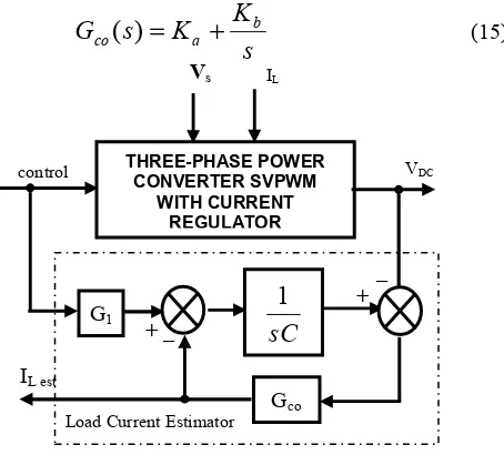
Load Current Estimator
The load current can be estimated by applying an observer as shown in Fig. 5. From (12) the estimated load current can be obtained as:
)
(
)
(
)
(
)
(
I
s
s
G
sC
s
G
s
I
L co co Lest+
=
(14)Observer compensator that used in this paper consists of proportional and integral gain, or
s
K
K
s
G
b aco
(
)
=
+
(15)
Fig. 5. Load Current Estimator
THREE-PHASE POWER CONVERTER SVPWM CURRENT REGULATOR VDC IL Vs k Is
sC
1
G1 k VDC _ + IL irectcontrol THREE-PHASE POWER VDC
CONVERTER SVPWM WITH CURRENT
REGULATOR
Vs IL
sC
1
G1
Gco
IL est
+ _
_ +
[image:2.595.57.289.512.623.2] [image:2.595.310.537.534.739.2]Gain Gco must be selected during the observer
compensator design to obtain a quick response with less noise. The load current control makes it possible to quickly generate a reference control signal, so that it is also possible to improve the voltage response with respect to the load change In this way it is also possible to estimate the load current by applying the observer shown in Fig. 6. The advantage of this is that the current sensor is no longer required. At steady state, the DC load current will be proportional to the control signal, with constant maximum phase voltage and DC voltage. By using this configuration in Fig. 2, it is apparent that there is a relationship between control sides and the DC sides. The rectified current can be determined using (11) or in other word that rectified current can be regarded as a control signal quantity referred to DC-side. Similarly, it is also possible to estimate the load current refer to control-side iest as:
Lest
m ph
DC
Lest
i
v
v
i
2 '
3
2
=
(16)Controller
The controller, used to generate control signal k is constructed using the following equation:
dt
e
K
e
K
i
G
k
=
2 est+
p+
i∫
(17)In (11) the error signal e is the difference of actual DC voltage and the reference, Kp and Ki are the proportional
and integral gains of PI controller respectively, and
1 2
1
G
G
=
(18) [image:3.595.333.517.466.746.2]An addition, a block is required to limit the control signal. DC voltage overshoot at start time can be eliminated using a low pass filter prior to voltage reference.
Fig. 6. The proposed Load Current Control
Fig. 6 also shows the block diagram of the proposed load current control for three-phase power converter SVPWM with current regulation.
IV. SIMULATION RESULTS
The simulation results show the response of the voltage on load changes and line currents of three-phase power converter with current regulation between conventional PI-controller and load current control method.
The parameter of three-phase power converter SVPWM with current regulation for the simulation is shown in Table. I.
TABLE I.
PARAMETER OF THREE-PHASE POWER CONVERTER
Parameter Value
Phase voltage 100 V peak
Frequency 50 Hz
DC bus voltage 300V
Inductance of Reactor 300mH
Internal Resistance of Reactor 0.2 ohm
DC bus capacitance 1000uF
Load resistance on full load 60 ohm
Sampling Frequency 10kHz
In this simulation experiment, both converters will be tested on load resistance changes from 60 ohms to 240 ohms at time t=0.3 sec (Fig. 7a and Fig.8a)
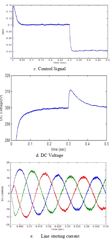
Conventional PI-Controller
The dynamic behavior of the control signal, currents, and voltages is shown in Fig. 7. In Fig. 7c the control signal goes from the limit value (0.16 or 16 A peak line current) to 0.1 (or 10 A peak line current) on full load resistance (60 ohm). At t=0.3 sec, the control signal goes up to 0.025 (or 2.5A peak line current). The load change causes the overshoot of around 12 volt (4%) at t =0.2 sec (Fig.7d)
a. Load Resistance
[image:3.595.58.288.505.614.2]c. Control Signal
d. DC Voltage
[image:4.595.323.509.69.606.2]e. Line starting current
Fig. 7. Experimental Results for Conventional PID
Load Current Control
The dynamic behavior of the control signal, currents and voltage are shown in Fig. 8 It can be seen that the control signal goes up from limit value (0.2 or 20 A peak line current) to 0.1 (or 10 A peak line current) on full load resistance (60 ohms). At t=0.3 sec control signal goes up to 0.025 (or 2.5A peak line current). The load change causes the DC voltage overshoot of approximately 2.5 volts (less than 1 %) in time 0.015 sec (Fig.8d)
a. Load Resistance
b. Current Load
c. Control Signal
d. DC Voltage
e. Line Starting Current
Fig.8. Simulation Results for Load Current Control
As seen in Fig. 8e the input line currents produced in the power converter SVPWM with current regulation using load current control have sinusoidal waveform and to be in phase to the phase voltages. In transient time, peak current will not exceed to 20A.
V. CONCLUSION
[image:4.595.88.276.71.478.2]rectified current. When implementing the load current observer, the current sensor on DC side is no longer required. From the simulation results, it is apparent that the proposed load current control method produces good dynamic behavior of the DC voltage and sinusoidal waveform of the line currents with unity power-factor.
REFERENCES
[1] Rathnakumar D., Lakshmana Perumal J., Srinivasan T., “A New Software Implementation of Space Vector PWM", SoutheastCon,
2005, Proceeding IEEE, pp.131-136, September 2002.
[2] Kocalmis, A., Sunter, S., “Simulation of a Space Vector PWM Controller For a Three-Level Voltage-Fed Inverter Motor Drive ”, IECON 2006-32nd Annual Conference on IEEE Industrial Electronics. pp. 1915–1920, 6-10 Nov. 2006.
[3] Iqbal, A., Lamine, A., Ashra, I., Mohibullah, “Matlab/Simulink Model of Space Vector PWM for Three-Phase Voltage Source Inverter ", Universities Power Engineering Conference, 2006. UPEC '06. Proceedings of the 41st International, vol. 3 pp. 1096– 1100, 6-8 Sept. 2006.
[4] Zheng Zheng; Cong Wang; Haijun Tao, “Research on three-phase PWM rectifier based on predictive control ", ICIT 2008. IEEE International Conference on Industrial Technology pp. 1-3, 21-24 April 2008.
[5] Min, B.-D., Youm, J.-H., Kwon, B.-H, “SVM-based hysteresis current controller for three-phase PWM rectifier”, Electric Power Applications, IEE Proceedings, vol. 146, Issue 2, pp. 225–230, March 1999.
[6] Saetieo, S.; Torrey, D.A, “Fuzzy logic control of a space-vector PWM current regulator for three-phase power converters", IEEE Transactions on Power Electronics, vol. 13, Issue 3 pp. 125-133, May 1998.