• •
• •
Sue Blackman
Unity
for
Absolute Beginners
GET ON THE FAST TRACK TO BECOMING A
GAME DEVELOPER WHILE LEARNING UNITY
For your convenience Apress has placed some of the front
matter material after the index. Please use the Bookmarks
v
Contents at a Glance
About the Author ...
xiii
About the Contributor ...
xv
About the Technical Reviewer ...
xvii
Acknowledgments ...
xix
Chapter 3: Scene Navigation and Physics
■
...
103
Chapter 4: Importing Static Assets
■
...
153
Chapter 5: Introduction to Scripting with C#
■
...
197
Chapter 6: Mecanim and Animation
■
...
243
Chapter 7: Populating the Game Environment
■
...
291
Chapter 8: Weaponry and Special Effects
■
...
339
Chapter 9: Incorporating Unity 2D
■
...
389
Chapter 11: Bonus Features
■
...
525
Appendix A: Rigging with Mixamo
■
...
565
xxi
Introduction
The Unity community is very large and very helpful. There are videos, code, and 3D assets available on any number of topics, and the Unity help documents have recently undergone a major update. But if you are new to any or all of the components of game development (scripting, 2D or 3D art asset creation and manipulation, or game design in general), you have probably discovered how overwhelming it is to make sense of it all.
One of the biggest challenges is to learn how to bring it all together. Unlike short topic videos, this book takes you through the process of creating a game that seems very simple at first glance, yet becomes more sophisticated as you work your way through the design and creation process.
One of the great advantages books have over videos is the luxury to spend time on explanations. In game development, there are always several different ways to solve design and technical problems, but there is rarely a “best” solution. And unlike a large studio, where budget and time constraints dictate a highly detailed game document, you will discover that the game design and creation process must be flexible in order to be able to finish a game or even a working prototype.
About the Unity Game Engine
Unity provides an excellent entry point into game development, balancing features and functionality with price point. The free version of Unity allows people to experiment, learn, develop, and sell games before committing any of their hard-earned cash. Unity’s very affordable, feature-packed Pro version is royalty free, allowing people to make and sell games with the very low overhead essential to the casual games market.
Will I Have to Learn to Script?
You don’t have to be a programmer to make your own game with Unity, but you will need to be able to understand enough of what the scripts do to know what can be tweaked to your advantage or decide if a particular script will suit your needs.
Most game play needs to be scripted in Unity, but there are hundreds of scripts already available that can be readily reused. Unity ships with several of the most useful. More can be found by searching the forum, Wiki, or UnityAnswers. Many forum members will even write bits of script for less adept users. In the Collaboration section of the forum, you can even find scripters looking to trade for art assets. By the end of this book, you should know enough to be able to take advantage of the wealth of material available from the Unity community.
Games, by their very definition, are about interaction; even with games that are largely controlled by physics, logic-driven cause and effect is what differentiates games from linear, plot-driven passive media. Even the most “artist friendly” game engines need scripting to move beyond simple environmental walkthroughs. If you have no previous scripting experience, you will find that this book’s aim is to familiarize you with scripting a few lines at a time, while providing visual feedback as often as possible. If you find you enjoy the scripting part of the project, feel free to delve deeper into programming with a more conventional approach.
What About Math?
One of the most common things heard in the game industry by artists and programmers alike is, “If I’d known math was going to be so useful, I would have paid more attention in class.” Although it helps to have a good background in math, there are plenty of resources for both code and mathematical functions to help you solve a particular problem. And, as always, there are plenty of people on the Unity Forum and Answers who may be willing to help as long as you can show that you have spent a reasonable amount of time trying to solve it yourself.
Assumptions and Prerequisites
This book assumes that you are new to scripting, 3D and game design, and/or the Unity engine.
What This Book Doesn’t Cover
This book is not about conventional game design; it is more of a precursor, getting you into the habit of analyzing needs and weighing choices. Not only is creating a massive design document intimidating when you are the one who will have to implement everything, but it is likely to be unrealistic until you are more familiar with the engine and your own capabilities. More typically, you will find yourself building your game up a little bit at a time, prototyping ideas and functionality as you go along.
way a native speaker learns his own language. He is surrounded by it, immersed in it, and allowed to tinker with it to slowly gain a basic working knowledge of it. Don’t worry about remembering it all. Some things you will use throughout the project, and others you will be encouraged to take note of for future reference.
Conventions Used in This Book
1. Instructions look like this.What Is the General Structure of this Book?
Tip Follow this format.
Code looks like this
Platform
Chapter
1
The Unity Editor
The most exciting part of learning a new application is getting it installed and firing it up for the first time. Following that, the most frustrating part can be the process of becoming familiar with its editing environment. Unity is no exception, especially if you are already familiar with DCC (digital content creation) applications. In this chapter, you will be introduced to the Unity editor and many of its key concepts. As this will serve as a light overview for the rest of the book, don’t stress over trying to remember it all.
Installing Unity
The first order of business is to download and install Unity if you have not already done so.
Unity has two license types: free and Pro. When you download and install Unity for the first time, you will have the option of using a free 30-day trial of the Pro version. It can be selected as a third option right in the license dialog upon installing Unity or upon returning the currently active license (an option that allows you to move Pro licenses to different machines). With a few exceptions, most of the Pro features are aimed at the optimization of your projects and are beyond the scope of this book. If you are considering the purchase of Unity Pro, you should be aware that, with the exception of Windows Mobile, it will require a separate license for each of the mobile target platforms you wish to author for.
Unity User Account
To get started, go to www.unity3d.com/unity/download.
With the account created, you can download Unity for Windows or Mac. The download site will automatically offer the version that matches the platform you are currently on.
Installing
This book was written using Unity 4.5. Because Unity regularly makes changes that can affect your projects, you may wish to use the 4.5 version even if the current version is newer. If you prefer, you can install multiple versions of Unity on the same machine, providing you name the folders accordingly (e.g., Unity 4.5, Unity 4.6). You may only run one instance of Unity at a time, regardless of the version. If you choose to have multiple versions, you will be required to start Unity from the desired version rather than from the desktop icon or the project itself, as the previously run version will open by default.
If that sounds like too much trouble, you can always check the book’s thread on the Unity Teaching forum, http://forum.unity3d.com/forums/23-Teaching, where both errata and version-change solutions will be posted and updated as necessary. A search for the book’s title will help you find its thread.
1. Install Unity, following the prompts, including the sample project.
On a Windows machine, it will be installed in the Program Files x86 folder. Upon the release of Unity 5.0, when it will be fully 64 bit, it should install itself in the regular Program Files folder. The sample project will be installed in Documents ➤ Public Documents ➤ Unity Projects. On a Mac, you will find it in /Users/Shared/Unity.
At this point, you should now see the Unity icon on your desktop (Figure 1-1).
Figure 1-1. The Unity application icon on the desktop
2. Click the icon to open Unity.
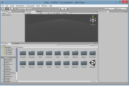
If the Scene window is blank, you can double-click the Unity icon in the Assets folder to load the AngryBots scene. The demo scene Unity ships with changes occasionally, so yours may be different.
Figure 1-2. The Unity sample project loaded
Tip When opening Unity from the desktop icon, it will open the previously opened project, provided it can be found.
From the Project Wizard, you can create a new project or browse to open an existing project. Initially, exploring the editor with a finished project will make more sense. You can obtain the sample project from the Unity Asset Store directly from a new project.
1. In the Project Wizard, select the Create New Project tab.
2. Set the Project Location manually using the Browse button, or accept the default name and location.
Figure 1-3. The Unity Project Wizard
Tip When you create a new project, you will be creating a folder to house the project. The folder is the project. You can only create a new project in an empty folder.
3. With the project name and location specified, click the Create button.
The new project and, as yet nameless, scene opens in the Unity editor.
Originally, if you pressed the Alt key down immediately after clicking the Unity icon on the desktop, it would force the program to start with the Project Wizard. Because that required excellent timing and/or a good dose of luck, Unity finally added the option to the Preferences section. While it may seem like a nice time-saver to automatically open your last file, it has its drawbacks. If the project has become corrupted, Unity will not be able to open it (giving you access to the file menu where you can open a different file). If you are using multiple versions of Unity, it will recompile data if the last project was opened in a different version. Depending on the version, the changes made could be permanent. To avoid complications, the best practice is to set the preference to always start with the Project Wizard.
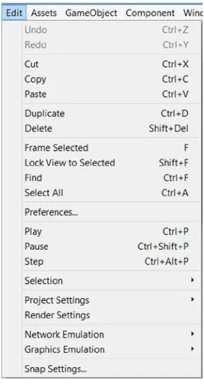
4. From the Edit menu, select Preferences.
General Layout
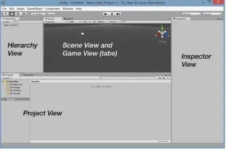
With the project loaded, you should see Unity sporting its default layout. If you are using the free version, the UI should appear in light gray (Figure 1-5). If you have purchased, or are evaluating, Unity Pro, the background will reflect the dark theme (Figure 1-6). For this book, the screenshots will utilize the light theme for better contrast. If you have Pro and prefer the lighter version, you can change the Skin in the General section of the Preferences.
Unity’s UI consists of four main “views” and several important features. The Scene view, Game view, Hierarchy view, and Inspector view (typically referred to as the Inspector) are generally accessible in any of the layout options, as are the playback controls, coordinate system options, and object/viewport navigation buttons (Figure 1-7). If the term “views” seems a bit odd, it helps to know that depending on which view is active, your input (or the events it triggers) will generate different results. The first click in a different view will set the focus to it.
With the default layout, the main feature is the Scene view. This is where you will be able to arrange your 3D assets for each scene or level in your project.
In the tab next to the Scene view, you will find the Game view. In the default layout, when you click the Play button, the Game tab is automatically opened. The game view is where you will interact with your scene at runtime to test your game play.
To the left of the Scene/Game viewports, you will find the Hierarchy view. This is where you will find the objects that are currently in the loaded scene or level.
Below the Scene/Game view is the Project view. This contains the resources or assets available to the current project. This folder corresponds directly to the project’s Assets folder on your operating system. Deleting files from the Project view will send them to the trash on your computer. If you author from an external hard drive, you should be able to locate the deleted files in the drive’s own trash folder. The main point here is that there is no “undo” for these deleted files.
To the far right, you will find the Inspector. This is where you will have access to the parameters, options, and other particulars of selected assets, from the Hierarchy or Project views, as well as general project-related settings.
At the top left, you will find the navigation controls that will allow you to move and arrange objects in
To the right of the navigation tool controls are the coordinate system options. Here you can specify Global or Local coordinates as well as using the object’s designated Pivot Point or the Center of its bounding box as the rotation point.
In the top center, you will find the Playback buttons. The Play arrow will put you in Play mode, where you can test your game’s functionality and presentation in a Windows or Mac environment. The Background color of the UI will also change, alerting you to the fact that you are in Play mode. The Play button becomes a Stop button once you are in Play mode. You also have the option to Pause the game, using the middle button, or to step through one frame at a time, using the right button.
At the top right, you will see two drop-down menus. The Layers button will allow you to set various Layers to be active or inactive during Play mode, or define new layers. The Layout drop-down menu provides a quick way to switch between several popular layout configurations.
Menus
The menu bar consists of seven menus, a few of which may already be familiar to you from other applications.
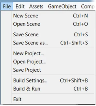
The File menu (Figure 1-8) is where you will save and load both scenes and projects. It is also where you will build, or compile, your game before sharing it with others.
Figure 1-8. The File menu
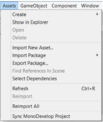
In the Assets menu (Figure 1-10), you will see the various options for creating, importing, and exporting assets. This extremely useful menu can also be accessed in a couple of different places in the editor, as you will see throughout the book. Topping the list is the Create submenu. This is where you will create most of your Unity-specific assets, such as scripts, materials, and a variety of other useful things. Along with the menus for importing assets such as textures and 3D models, you will find a mainstay of Unity game development: the means of importing and exporting Unity “packages.” Packages are the vehicle for transferring all things Unity with their relationships and functionality intact.
In the GameObject menu (Figure 1-11), you will be able to create several types of pre-set objects, from the most basic of Unity objects, an “Empty GameObject,” to primitives, lights, cameras, and a nice variety of 2D and 3D objects. Also of note in this menu are the bottom three commands. They are the means for positioning objects relative to one another, including Cameras and their views. In Unity, anything that is put in your scene or level is called a gameObject (lower case g). More than just Unity's name for an object, gameObject specifically refers to an object that inherits from the GameObject class (upper case G), that is the code that defines the top level object and its basic behavior.
Figure 1-11. The GameObject menu
Figure 1-10. The Assets menu
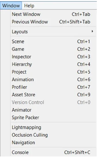
The Window menu (Figure 1-13) is where you can go to open or change focus to Unity’s standard and specialty views or editors. The shortcut keys are listed if they exist. Note the Asset Store item. This will take you directly through Unity’s Asset Store, where you can import assets directly into your game.
Figure 1-13. The Window menu
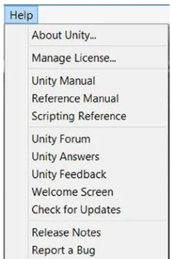
The Help menu (Figure 1-14), as expected, will provide you with the version number and license information of your Unity installation. In this menu, you can find access to the three main pieces of Unity documentation: the Unity manual, where you can find information on the workings and concepts behind much of the Unity workflow and features; the Reference Manual, where you can get specific information on Unity components; and the Scripting Manual, where you can find Unity-specific API classes, examples, and scripting tips. Additionally, the menu supplies links to the Unity Forum and Answers (when you just need a quick solution) and a means of reporting a bug should the need arise.
Figure 1-14. The Help menu
Getting Started
Each of Unity’s “views” comes with its own options and settings. Most are along the top of the viewport or panel, but there are a few that are located at the bottom. Once again, this is just a quick overview to familiarize you with some of their key features.
If you didn’t choose to download and install the sample scene, AngryBots, with your Unity install, you will need to fetch it from the Unity Asset Store if you wish to follow along with the next
section’s exercises. It is a free download and can be found in the Complete Projects category, Unity Technologies section.
1. From the Windows menu, select Asset Store.
2. Select the Complete Projects category.
3. Select the Tutorials subsection.
4. Select Angry Bots.
5. Click the Download button’s drop-down arrow (on its right side).
7. Close the Asset Store window when the project has finished downloading.
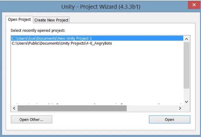
8. In the Unity editor, from the files menu, select Open Project.
The Project Wizard opens (Figure 1-15).
Figure 1-15. The Project Wizard
9. Select Open Other…
10. Navigate to where the project was installed, and select the parent folder, 4-0_AngryBots.
When Unity opens a project that you were previously working on, it will open to the scene you were editing or viewing. If this is the first time the project has been opened, it will open to a new, unnamed scene. Since all new scenes are created with a default camera, it won’t be entirely empty, but it also won’t do you much good as you check out the various views.
One of the first things you will learn to do in Unity is to keep your projects organized. While it’s not mandatory to do so, you will find that most developers create a folder called Scenes to store the game’s scenes or levels in. You will find that AngryBots does indeed have a Scenes folder, but the main scene was left on its own in the root folder. Unity helps you to locate various types of resources through the use of various icons. The icon used for scenes is, appropriately, the Unity production.
2. Double-click on the AngryBots scene name and/or icon to load the scene.
The contents of the scene are shown in the Hierarchy view. The Scene view reflects the last observation point from the last scene seen in the Unity editor, regardless of what project it was in.
Navigating the Scene View
The first thing you will probably want to do is explore the loaded scene in the Scene view. Because viewport navigation varies quite a bit in 3D applications, this is a good place to start your Unity experience. Let’s start by focusing in on an object in the Hierarchy view.
1. In the Hierarchy view, double-click on the Main Camera to focus the Scene view to it.
Figure 1-16. The AngryBots scene in the Project view
Your exact view may vary, but from any particular location, it will be looking toward the Main Camera object (Figure 1-17). You will learn how to adjust the icon size and type in the Scene a little bit later.
Figure 1-17. The Main Camera “found” in the Scene view
When a camera object is selected, you will also get an inset showing what it sees.
2. To orbit around the Scene view’s current focus, Main Camera, hold the Alt key down on the keyboard, press the left mouse button, and move the mouse around.
The scene view is orbited around the current center.
3. Release the Alt key, press the middle mouse button or roller, and move the mouse.
The view is panned (moved up/down/left/right).
4. Holding the Alt key down once again, press the right mouse button and move the mouse.
This time, you are zooming the scene in and out. You can also zoom by rolling the middle mouse roller.
5. Release the Alt key, and continue to hold the right mouse button down as you move the mouse.
With no Alt key, the view is rotated from the viewpoint’s origin.
You can also perform fly-through navigation through the scene.
6. Hold the W key down on the keyboard and then press the right mouse button. Move the mouse to perform direction changes.
Understanding the Scene Gizmo
In the Scene view, you have several options for working in the viewport as you create and refine your scene. The two main options are to view the scene in perspective mode or an isometric mode.
1. Double-click the Main Camera once again in the Hierarchy view to get back to some scene objects.
2. Using the right mouse button (or any of the alternative methods), rotate the view and observe the Scene Gizmo (Figure 1-18).
Figure 1-18. The Scene Gizmo in the upper right corner of the Scene view
The Scene Gizmo indicates the cardinal direction of the global or world directions. Currently you are seeing the view in a perspective view, Persp, but you can use the Scene Gizmo to change to an iso view, Iso. An 'iso' or isometric view is a view often used in drafting to create a 3D view without the vanishing point perspective of the human eye. Unlike perspective, where objects farther back in the scene appear smaller, in Iso, their size relative to each other is always correct. When coupled with the cardinal directions (front, back top, bottom, left and right), Iso will show a flat orthographic view that can make positioning objects much more accurate. When rotated off of the side or top/bottom views, the view becomes isometric. You can toggle the lable to return to a perspective view.
3. Select the Y or top view arrow on the gizmo.
4. Click on the Top label.
Now the view is a flat orthographic view, as indicated by the three parallel bars of the new label icon (Figure 1-20).
Figure 1-19. The perspective Top view
Figure 1-20. The ortho Top view
5. Try clicking the other Scene Gizmo arrows to see the other views.
These views will allow you to position objects with respect to each other with far more accuracy than a perspective view.
This time the view becomes an isometric view (Figure 1-21). If you have an engineering background, you will recognize this as a typical means of depicting objects in 3D without having to calculate true (human-type) perspective. It is also used in many world-building games, such as Blizzard’s Warcraft 3 or StarCraft.
Figure 1-21. The Iso, or isometric view
Figure 1-22. The Scene
7. Return to a perspective view by clicking the iso label.
Exploring the Views
Now that you are becoming more adept at manipulating the viewport, you can check out several of the tools and features available to you with each of the main views.
Hierarchy View
The Hierarchy view is essentially a list tree of the objects currently in the loaded or active scene. The key word here is “currently” because during run-time, objects can be “instantiated” (created on the fly) or destroyed (deleted from the scene). This is an important concept in Unity, and it is one of the reasons that most changes made during run-time are not permanent. On exiting Play mode, the Hierarchy view will be returned to its former state.
During your experimenting with the viewport, you may have accidentally clicked on an object in the Scene view. When selected that way, the hierarchy in the Hierarchy view will be expanded to show the picked object. As you may have noticed, some of the objects are children of children of the top-level objects in the scene. With this in mind, you can imagine how difficult it can be to locate particular objects in either the Scene or Hierarchy view. As the book’s project comes together, you will be importing and using several prefabs (Unity’s term for reference objects) and will want a quick means of locating them in the current scene.
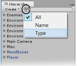
Fortunately, Unity has a nice search function for that very purpose. At the top of the Hierarchy view, to the right of the Create drop-down arrow, you will see a small magnifying glass icon and its drop-down arrow. The drop-down menu will let you filter for All, Name, or Type. Let’s start with Type (Figure 1-23).
Figure 1-23. The Search feature’s filters
1. Press the drop-down arrow next to the search icon, and select Type.
2. In the text file to the right, type camera.
Before you can finish typing, Unity lists the cameras in the scene. In this case, there is only one, Main Camera. If you select it in the Hierarchy view, it is also selected in the Scene view, along with its view in the Camera Preview window. Note how everything else in the scene has been grayed out.
The Scene view is returned to normal, but the selected object remains highlighted in the Hierarchy view.
4. Next, change the filter back to All and type confused.
5. Select the only object that comes up, ConfusedEnemyMech.
6. Double-click to see the view focus in on it.
7. Click the x to return the view to normal.
8. This time, type in something more generic, pipe.
Because there are several objects in the scene with the word pipe in their name, the list of possible objects is quite long. In the Scene view, they are all “un-grayed,” helping you to find the one you want fairly quickly (Figure 1-24).
Figure 1-24. The options for a scene object with “pipe” in its name
9. Click the x to return the Scene view to normal.
Scene View
The Angry Bots scene provides you with plenty of variety to explore the Scene view’s tools and features. Because there are lots of options, you will just take a look at some of the more commonly used features.
1. Deselect any objects you’ve got selected by clicking in a blank area of either the Hierarchy or Scene view.
2. Zoom back far enough to see about half of the scene.
Of the five, the first three should be easy to understand, especially if you have had any background in 3D modeling or have ever watched a “making of” video of any of the pioneers of the CG movie industry’s 3D animated films.
4. Try selecting Wireframe and then Textured Wire.
You may have noticed that meshes automatically show as textured wire when selected. The
difference here is that the wire is black, not light blue, allowing you to continue to locate the selected item in the Scene view. In Wireframe, you can see how 3D objects came to be called “meshes,” as they resemble wire meshes.
The next option to the right shows RGB (Figure 1-26). This set of display options has to do mostly with texture maps. RGB, the default, shows the red, green, blue part of an RGBA texture.
Figure 1-25. The viewport display options
Figure 1-26. The scene view options
5. Select the Alpha option.
6. Select the Overdraw option.
Overdraw, the third option, shows how many objects must be drawn on top of each other from the current vantage point. The denser or brighter the display (Figure 1-28), the more objects there are that must at least be sorted, if not actually drawn. In mobile games, regardless of device and operating system, this type of sorting is very costly and should be kept to a minimum.
Figure 1-27. Textures displaying alpha channels
Figure 1-28. Possible overdraw problem areas showing as bright areas in the Scene view
The final option shows the MIP map distance, with no color being the full original-sized texture. As the tint goes from blue to clear to gold through to red, the smaller, blurrier maps are substituted, preventing the sparkly artifacting effect seen as the camera pulls back away from the object. Blue uses a blurred version of the map when the camera is close enough to see pixilation in the texture. You will learn more about MIP mapping when you work with imported images later on.
1. Zoom in close enough to the compound floor by using the mouse roller or by holding the Alt key, pressing the right mouse button, and moving the mouse to see the floor tinted blue at close range.
2. Zoom out slowly, and watch as the tint goes to no tint then to red (Figure 1-29).
Figure 1-29. Color tinting indicating which version of MIP map is shown according to the distance
An absence of tint is the native image. Blue is a blurry version of it you can use so that you won’t see each and every pixel up close. Red is a blurred version of it you can use so that you won’t see the sparkly artifacting common to low-resolution videos. To see the MIP maps generated from the imported textures, you can select a texture and view it in the Inspector.
3. In the Project view, select the Textures folder from the Assets folder.
4. Locate and select the AngryBots texture in the second column.
5. At the bottom of the Inspector, in the Preview window, move the slider from the far right, slowly over to the far left.
The images are shown in increasingly blurry versions. They appear pixilated as Unity zooms in closer and closer and the versions are smaller and smaller.
The next option for the Scene view is the 2D toggle. If you are creating a 2D game, it makes sense to develop in the kind of view that matches the final output. A little experimentation shows that the 2D option is a preset to the Back view, with the iso option turned on (Figure 1-30). The view points in the positive Z direction. The Scene gizmo is hidden to prevent accidental viewport manipulation. Only Pan and Zoom are available.
Figure 1-30. The 2D toggle compared with the Back/iso view
The next toggle in the Scene view turns scene lighting off and on. When the scene lights are off, the scene is lit from the user’s viewpoint, straight into the scene, insuring the visible objects will be well lit. In the Angry Bots scene, the lighting has already been “baked” into most of the textures—that is, the textures themselves have been altered to appear as they are with the lighting on them. To see the lights being toggled off and on in this scene, you will need to locate one of the objects that receives dynamic lighting.
1. In the Hierarchy view, search for mine_bot.
2. Select one of the listed mine_bots, and double-click it to zoom in on it in the Scene view.
Now that you’ve seen that the bots and not the building receive lighting, you can test the Render Paths option in the first display drop-down menu.
4. Change the first Display option from Textured to Render Paths.
5. Zoom out until you can identify the various red tinted objects.
A closer inspection will show that they are all of the objects that are also receiving dynamic light during run-time.
The next button to the right is the Play Sound Effects toggle (Figure 1-32). It toggles audio on or off.
Figure 1-32. The Sound Effects toggle
Figure 1-31. The Scene Lights toggle: lights on (left) and lights off (right)
1. Toggle the Audio button on.
2. Search for and select polySurface5073 in the Hierarchy view.
3. Double-click on it to focus the Scene view to it.
The sound you hear is a 3D sound, and it can be heard only when you are close enough to the object. It is also set to be a looping sound.
4. With polySurface5073 selected, orbit the view until you have a good view of the sky and deck, and can hear the rain sound effect (Figure 1-34).
Figure 1-35. A close look at an animated material
Figure 1-34. A good view of the sky and outside deck
5. Toggle the Sky box on and off.
The hazy sky disappears and reappears. The skybox is a cubic map (a six-image collection) that is added to the scene through the use of shaders. It has no actual “box” geometry, so you never have to worry about the player getting too close to it.
6. Next, toggle on Animated Materials.
This distortion/reflection effect is achieved through the floor material’s shader. Many of the sample projects contain code and shaders that you can commandeer for your own projects, so they are well worth investigating, even if their functionality is past your current level of knowledge.
8. Turn off the Animated Material effect in the drop-down menu.
The next button is the Gizmos button/drop-down menu (Figure 1-36). This is where you can control which specialty icons will show in the Scene view and how they will be presented. Several types of gameObjects have standard gizmos already assigned and active in the scene. The most obvious are lights and audio, and—if you remember the new, almost empty scene when you opened the project—the camera. The gizmos help you to locate objects in the Scene view that have no mesh associated with them. The light icons, by the way, show the tint set for the specific lights they represent.
Figure 1-36. Gizmos drop-down menu
Figure 1-37. A good view of some specialty icons in the scene
1. Navigate the Scene view until you can see a nice selection of gizmos (Figure 1-37).
This view displays several spotlight icons showing the placement of lights in the wall’s can light fixtures, a point light, the lightbulb icon, and a couple of audio icons associated with each of the two mine bots guarding the area.
As the gizmos get larger, they start to fade out before they cover too much of the scene. As a default, they are set as 3D gizmos. They are obviously 2D icons, but they are adjusted in size depending on how close you are to them, giving you a better feel for where the actual gameObject is in 3D space. They are also occluded by mesh objects, as can be seen with the golden can lights on some of the walls. If you find the dynamic sizing distracting while working mostly in an overhead view, you may prefer to switch them to 2D.
3. Uncheck 3D Gizmos.
All of the gizmos within view are shown at a standard size. While this is obviously not practical for a first-person vantage point, it is useful for overhead editing. 2D icons are not affected by distance.
4. Switch the view to a top/iso view so you are looking down on the compound.
As you may remember, most of the lighting was baked into the textures, so most of the light gizmos you see are no longer in use. Fortunately, you can opt to turn icons off and on by type.
5. Open the Gizmos list again, and click the Light icon from the icon column.
All of the light gizmos are turned off in the Scene view.
6. Now turn off the Audio Source icons.
An overhead search of the compound should now find the lone camera icon, but you will also see several blue box outlines. Because the gizmos are associated with the components that dictate the object’s features and functionality, you can also assign icons to custom scripts, because scripts are also components. In Angry Bots, several of the scripts have gizmos assigned to them.
7. Open the Gizmos list again, and try unchecking the Rainbox gizmo check box on the far right of the script name in the Scripts section.
The blue rectangle gizmos disappear from the scene.
In Unity, you have the option of assigning custom icons as well as generic gizmos to specialty scripts. While it is beyond the scope of this book to cover that functionality, it should at least take the mystery out of some of the gizmos you come across in other people’s scenes.
The last item on the Scene view bar is the now familiar search feature. While it may seem redundant to have the search featureon both views, Unity allows you to fully customize which views are turned on and where they are placed, so you could possibly find it very convenient if you are using two monitors and have the Hierarchy view far removed from the Scene view.
Game View
Having dealt with the most complicated view, you can now take a look at the Game view.
1. Click the Game tab to the right of the Scene tab.
On the far left, the aspect drop-down menu allows you to specify an aspect ratio so you can make sure you will be seeing what your player will see (Figure 1-39). You can also add custom, fixed sizes by clicking the Add button (the plus sign) at the bottom (Figure 1-40).
Figure 1-39. The Free Aspect drop-down menu
Figure 1-38. The Game view options
Figure 1-40. On the left, the Add icon, and on the right, the custom option popup for a fixed-size view
The next option is “Maximize on Play” (Figure 1-41). When toggled on, this will hide all other views and maximize the Game view on Play. If you have stipulated a fixed window size, Unity will do its best to match it.
Figure 1-42. The Stats window during run-time
1. Toggle the “Maximize on Play” option on.
2. Click Play.
The Game window is maximized, and the other views are toggled off.
3. Stop Play mode by clicking the Play button again.
The views return to their original layout.
Next to the “Maximize on Play” option is the Stats button. The Stats window will show you the statistics for your game during run-time. The most familiar will be the frame rate at the upper right. The various items in the list may be a bit more cryptic, but all affect frame rate in one way or the other.
1. Toggle on the Stats window, and click Play.
2. Observe the frame rate and other items as you take the character through the compound (Figure 1-42).
3. Stop Play mode, and turn off the Stats window.
The last item on the Game view bar is the Gizmos toggle. Like the Effects drop-down menu, this one works as a toggle when clicked or can be set to selectively see the gizmos you prefer.
Project View
Next up is the Project view. You have already used it a few times, but it has some nice functionality that you will want to be aware of. Before going any further, it is worth a reminder that the Assets folder on your computer is the Assets folder you see in the Project view. The most important thing to remember is that you can add to the folder through the Explorer (in Windows) or the Finder (on Mac), but you should not remove or rearrange resources except from within Unity unless you also include the object’s .meta file.
Besides the Create drop-down menu, which is another location from which you can access some of the Assets menu’s functionality, one of the main features of the two-column Project view is the Favorites options found above the Assets folder section (Figure 1-43). It allows you to see all assets of the listed types.
Figure 1-43. The Favorites options
1. Select each of the filters, and watch the results.
The materials are displayed on spheres as with most 3D applications. The models and prefabs are shown with thumbnail images, and the scripts are shown as a simple list with their script type icon. If you are an artist and have created most of your own models and textures, you will probably find it quicker to locate them by name. Conversely, if you are working with assets created by someone else, you may not know the names but will know the one you are looking for when you see it. To keep a good workflow for either scenario, Unity has provided a slider at the bottom of the view that will size the thumbnails up or down. More importantly, on the left end of the slider, it reverts to names with type icons.
2. Select the All Models filter.
4. Try selecting the folders from the Assets folder to see their presentation.
You’ve probably noticed the familiar Search field at the top of the Project view. With folders selected, you can type in a name or use the small icons at the right of the field to filter by type or label. You can also save the search if you find yourself repeatedly looking for the same item. When using the filters, however, you get another option. You can search the Asset Store directly if you find you need a particular asset. The store items are divided into Free or Paid assets, so you can search the thumbnail previews for items of interest.
5. From Favorites, select All Models.
6. Click on the Asset Store option at the top of the second column.
7. Open the Free Assets section, and click on a model that looks interesting.
The information about the model is shown in the Inspector, and you have the option of importing it directly to your scene or going out to the Asset Store for some serious shopping (Figure 1-45, left). For the Paid Assets, you will see the price instead of the import option (Figure 1-45, right).
8. For fun, type in rabbit (or some other object of interest) in the search field. The item or related items, if any can be found, appear in the project view.
The last bit of Project view functionality will allow you to switch from the default Two Columns Layout to the original One Column Layout (Figure 1-46). These options can be located by right-clicking over the Project tab. The One Column Layout can be more useful, depending on the overall layout of the UI or where in the development process your game happens to be. You will get a chance to give it a try later in the book.
The Inspector
The Inspector is the last of the main views or panels. As you may have noticed, its functionality and options are directly related to the item that is selected elsewhere in the editor. As you become more familiar with Unity, you will spend a lot of time in the Inspector. It is where you will gain access to almost everything related to your game in Unity.
Layout
Now that you have spent a bit of time with the Unity views and panels, it’s time to see about re-arranging them as your needs change. As you open various sample scenes, you will see many different layout preferences. The current default layout shows the loaded scene and assets folder off to nice advantage, so these are good choices for a first look. As you start developing your own games, however, you may find it useful to try other preset layouts or even customize your own.
1. Locate the Layout drop-down menu at the upper right of the editor.
2. Open it, and check out some of the preset layout options (Figure 1-47).
Figure 1-46. Adjusting column layouts
3. Select the “2 by 3” option.
This layout is useful for changing and checking on objects during run-time, as you get to see both views at the same time. Its tall vertical views or panels make it easier to access large numbers of assets in the Hierarchy view without resorting to the Search feature. Its main drawback is that the Project view’s Two Column Layout does not lend itself to a tall vertical column very well. This is when the Single Column layout is useful.
4. Right-click over the Project tab, and select the Single Column Layout.
The Project view is now essentially the contents of the Assets folder, and the file structure has the standard operating system hierarchy (Figure 1-48).
Figure 1-48. The 2x3 Layout and Single Column Project view
Besides the preset layouts, you can also float and rearrange the views manually.
5. Click and drag the Hierarchy tab around the editor.
Project Structure
Because no job is done until the paperwork is finished, you ought to have a basic understanding of how Unity projects are organized before you jump in and start creating a game. For the most part, everything you create will reside in the Assets folder. It is up to you to keep things organized as you develop your game. And as a gentle reminder, avoid re-arranging the contents of the project view outside of the Unity editor.
File Structure
Let’s create another new project. This will give you a chance to see how Unity manages the folders that you create or import into your project. The file structure in Unity’s Project view is drawn directly from the Windows Explorer (or the Mac’s Finder). To be able to see the correlation, you will add some common packages at the same time as you create the project.
1. From the File menu, select New Project.
2. Under Project Location, Browse to a location of your choice and create a folder for your project.
3. Name the project/folder UnityTest, and choose Select Folder. 4. Under “Import the Following,” select:
CharacterController.unityPackage
Scripts.unityPackage
TerrainAsssets.unityPackage
5. Click the Create button.
6. At the dialog that asks if you want to save changes in the AngryBots scene, select Don’t Save.
Unity re-opens, using the layout from the previous session. A new, untitled scene is loaded.
7. Expand the Standard Assets in the Project view.
You will see folders for the three Unity packages you imported when the project was created (Figure 1-49).
8. Now, go out to your browser (Windows) or finder (Mac), and locate the project folder to see what was generated.
Beneath the folder you created for the project, you will find an Assets folder that contains the contents of the three imported packages in a Standard Assets folder (Figure 1-50).
Figure 1-50. The project, UnityTest, and its folders containing the imported assets in the Explorer
9. Expand the folders to assure yourself that they are the same folders as in the Unity Project view.
Three other folders were generated besides the Assets folder: Library, where relationships between assets are stored in the large number of Metadata subfolders; Project Settings, where game-related data not contained in regular assets is stored; and Temp. You should not make any changes to these folders. You may add assets directly to the Assets folder or subfolder, but you should not rearrange the contents (and yes, that is the third time that has been mentioned!).
Project Management
As you are probably beginning to understand, Unity’s file structure is fairly rigid. This ensures that assets will not go missing at crucial times.
Another important thing to know about Unity projects is that there is no quick way to back them up unless you are using a version-control system such as SVN, GIT, Perforce, PlasticSCM, or Unity’s own Asset Server. There is no option to “Save Project as…” To be able to copy a project, you must first close it. You will find that as you refine scripts along the development process, earlier test scenes may no longer work. Unity project files can get quite large, so it is well worth the time and space to make occasional backup copies for emergencies, for referencing earlier functionality, or for experimenting with alternative ideas in a nondestructive way. The finished projects for each chapter of the book are included in the book’s asset file, which you can download from the Apress website,
Load/Save
Also worth noting is the difference between saving a scene and saving a project. Changes made to the Hierarchy view will always require the scene to be saved. Changes in the Project view, because they are actually changes to the folders on the operating system, may not need to be saved. Assets that are created directly in Unity, even though residing in the Assets folder will probably need to be saved because of all of the path and relationship metadata they generate behind the scenes. Anything scene or project related that does not involve assets directly requires a project save. The bottom line is, paranoia runs deep; it is safest to get in the habit of saving both scene and project on a regular basis. You won’t be reminded to do so very often in the book, but that doesn’t mean you shouldn’t do so on your own!
Summary
In this chapter, you got a first look at Unity’s UI. Besides getting a brief overview of the major areas, you had a chance to investigate some of the functionality that will help you as the book’s project progresses. The biggest takeaway was in scene management, where you learned that you could add to the Assets folder from your operating system’s Finder or Explorer, but that you must not re-arrange assets outside of the Unity editor once they have been added.
Chapter
2
Unity Basics
While you can create some assets directly inside Unity, the building blocks for your scene will usually be based on imported assets. The in-game functionality, location, and final appearance, however, will be managed and completed within the Unity Editor. For that, it is necessary that you have a good understanding of Unity’s key concepts and best practices. In this chapter, you will explore and experiment with a good portion of the Unity features that don’t require scripting to be able to enjoy.
Unity GameObjects
In Unity, assets can be anything from textures and materials to meshes, scripts, and physics-related components. Whether they were imported or generated inside Unity, components are combined and manipulated to bring objects to life. Unity uses the term gameObject to represent objects because internally they belong to a (scripting) class named GameObject. When referring to a generic gameObject, this book will use the lowercase g. When scripting, the uppercase and lowercase g will refer to either the particular gameObject (lowercase g) or to the GameObject class (uppercase G) that holds the definitions and available functionality for all gameObjects.
The most basic of GameObjects (in the formal sense of the word) consists of little more than its transform. A transform is an object’s scale, orientation, and location in space. The gameObject itself can be used as a parent to manage multiple gameObjects, or it can be filled with components that define all manner of visual appearance and functionality. Unity provides many prebuilt gameObjects. Some are simple primitives ideal for quickly prototyping your game. Others are full-fledged systems for complex and sophisticated objects and special effects.
If you have no prior experience with 3D assets, let alone game-type functionality, don’t worry, you will begin with the basics and go on from there.
Creating Primitives
of longitudinal and latitudinal segments it has. A box or cube is defined by height, width, length, and its number of segments. When an object cannot be described by a set of parameters, it is called a “mesh.” A mesh is a collection of vertices, edges, and faces that are used to build the object in 3D space. A primitive is a mesh, but a mesh (no parametric way to define or describe it) is not a primitive. In Unity, you have less control over the parameters, but the included 3D gameObjects are primitives, nonetheless. These primitives can be used as is or as the base for more complex gameObjects.
Let’s start by using the project created in the last section of Chapter 1, the UnityTest project.
1. If Unity is not already open to the UnityTest project, click the Unity icon on your desktop.
2. In the Project Wizard, select the UnityTest project.
While the scene is small and you are not adding game play, it will be useful to use the default layout.
3. Click the Layout button at the top right of the editor to open the list of presets.
4. Select Default.
The layout reverts to having the Hierarchy view on the left, the Inspector on the right, the Scene and Game views tabbed in the center, and the Project view underneath.
The project has a default, nameless scene, but it has not yet been saved.
5. From the File menu, select “Save Scene as.”
6. Save the scene as Primitives.
The new scene asset appears in the Project view, sporting the Unity application icon (Figure 2-1).
Figure 2-1. The new Unity scene asset in the Project view
A cube is created in the center of the viewport.
Transforms
All gameObjects have a Transform component. It keeps track of where the object is in space, what its orientation is, and if it has been scaled. Unlike the viewport X, Y, and Z global coordinates, gameObjects can be moved, rotated, or scaled at will. You can transform them in edit mode, and they can be animated during runtime.
If you have not navigated through the scene view since the project was created, the cube should have been created at 0, 0, 0. Unlike many Autodesk products where Z is up in the world, in Unity, Y is the upward direction. You should see your cube with its transform gizmo, specifically the Position gizmo, clearly visible. The arrows follow the convention of RGB = XYZ, or the red arrow is the X direction, the green arrow is the Y direction, and the blue arrow is the Z direction. Z is the direction Unity considers as forward.
1. With the cube selected, look at the Transform component at the top of the Inspector (Figure 2-3).
Figure 2-3. The cube’s Transform component
2. If the X, Y, and Z positions are not all 0, you can type it in to move the cube to that location.
While you are in the Inspector, take a look at the cube’s Scale. It defaults to 1 x 1 x 1. Unity considers 1 unit to equal 1 meter, approximately 3 feet.
You don’t need to type values directly into the number fields, because many of Unity’s entry box labels act as sliders.
3. Position your cursor over the Rotation’s Y label.
4. Click and drag it left and right to rotate the cube in the Scene view.
5. Leave the cube at about -60 degrees.
7. Click on the Z arrow in the viewport, and drag the cube while watching the Position values in the Inspector.
The cube is moving in its local Z direction, but its X position is updated as well.
8. Change the coordinate system to Global, and pull the cube in the Global Z direction.
This time, the only value being updated in the Inspector is the Z Position. When you transform an object, its location and orientation are kept in world coordinates.
You can also rotate and scale objects using the transform modes at the top left. Just like position, rotate can use local or global coordinates.
1. Click to active Rotate mode (Figure 2-5).
2. Rotate the cube by placing the cursor over the circular parts of the gizmo and dragging.
3. Change the mode to Scale (Figure 2-6).
Figure 2-6. Scale mode and the Scale gizmo
Unlike position and rotation, Scale mode allows you to scale an object only on its local coordinate system. This prevents objects that have been rotated from getting skewed.
4. Scale the cube on any of its axes.
5. In the Inspector, set all of its Scale values back to 1.
6. Set the mode back to Move in the upper left corner of the editor.
7. Set the coordinate system to Local.
So far, you have dealt with only a single object. With multiple objects, there are some tools that will help you with positioning.
1. Hold the middle mouse button down, and pan the Scene view so that the cube is off to the left, but not out of the viewing frustum (the boundaries of the viewport window).
2. From the GameObject menu, Create Other, select Sphere.
3. The Sphere is created in the center of the viewport, not at 0, 0, 0 (Figure 2-7).
To move the sphere to the same location as the cube, you could copy and paste the values from the cube to the sphere, but that would be tedious. Instead, you will be using a typical Unity workflow where the target object is focused or framed in the viewport, then the object to move is moved to that location. Note that it will not affect the object’s orientation.
4. Select the Cube in the Hierarchy view.
5. Double-click the cube in the Hierarchy view, or move the cursor to the Scene view and press the F key.
The Scene view zooms in to the selected object. Unity calls this action “frame selected.”
6. Now select the sphere by clicking on it in either the Hierarchy view or the Scene view.
7. From the GameObject menu, select “Move to View.”
The sphere is moved to the center of the viewport as defined by the cube’s location (Figure 2-8).
Figure 2-8. The scene focused to the cube, and the sphere moved to the scene’s focus
8. Select the cube, and check the Inspector for its Rotation values.
It should still have -60 (or whatever you left it at) as its Y Rotation value.
9. Select the Sphere, and check its Rotation values.
Duplicating GameObjects
In Unity, you can use Ctrl +D (z+ D on Mac) to duplicate objects. Some items—such as materials, textures, scripts, and many others—must have unique names and will automatically be incremented upon duplication. GameObjects, however, can share names, as you may have noticed with the AngryBots game. If you think you will need to access an object as an individual, you should give it a unique name.
In this section, you will name the duplicates for easier identification after clearing the Sphere from the Scene view.
1. Select the Sphere in the Hierarchy view.
2. At the top of the Inspector, to the left of its name, uncheck the check box to deactivate the Sphere in the Scene view.
The Sphere disappears from the Scene view, but its transform gizmo remains visible as long as it is selected.
3. Click in an empty spot in either the Scene or Hierarchy view to deselect the deactivated Sphere.
In the Hierarchy view, the deactivated Sphere’s name is grayed out (Figure 2-9).
Figure 2-9. The deactivated Sphere in the Hierarchy view
4. Select the cube from either the Scene view or the Hierarchy view.
5. From the right-click menu, select Duplicate.
6. Rename the clone, Cube1.
7. Pull Cube1 away from Cube so they are at least a meter (the original size of the cubes) apart.
8. With either cube selected, press Ctrl +D (Command + D on Mac) to clone another cube.
9. Rename the new cube, Cube2.
Arranging GameObjects
Typically, when you are creating an environment with a lot of duplicate geometry, you will import the original and then make duplicates of it in the scene. Although it doesn’t reduce the overhead during runtime, it does reduce disk space, or in this day and age, download time.
The end result is that the modular asset must be arranged in the scene. To help with that task, Unity has a very nice vertex snap feature.
1. Arrange the view so that you can see all three cubes easily.
2. Select Cube1.
3. Hold the v key down on your keyboard, and move the cursor around the cube.
The transform gizmo jumps to the closest vertex.
3D MESH COMPONENTS
If you are new to 3D, you might not know that mesh objects have three component parts: vertices, edges, and tris (short for triangles). A triangle, sometimes called a face, is the smallest surface that can be rendered. It is defined by three vertices and the three edges that connect them (below, left). Unless you are using a two-sided shader (a “shader” contains the code that tells the graphics hardware how an object is drawn on screen), faces are only “drawn” or “rendered” on one side, their face normal side. The “normal” is an imaginary line perpendicular to the face that indicates its “outward” or visible side (below, right).
4. When the cursor snaps to the lower vertex closest to the next cube over, press and hold the left mouse button, and then drag it over to the next cube.
5. With the mouse button down, move the cursor around the target cube and watch the original vertex snap to its new target.
6. When you are happy with the alignment, let go of the mouse button to finalize the arrangement.
You can also set objects to snap at intervals and use a rotation snap.
1. Select one of the cubes, and set its rotation values back to 0. 2. From the Edit menu, at the very bottom, select Snap Settings.
The grid snaps are set to 1 unit. This means that the object must be within 1 unit or meter of the grid intersection before they will snap. Because the cubes’ pivot points are at their centers, the cubes were originally halfway down through the scene construction grid. The first thing to do is move it up.
3. Select the cube again and, holding the Ctrl key (Windows) or the z key (Mac), move the cube up until it snaps its base to the grid floor.
4. Try snapping the cube to the grid in the Global X or Z direction.
Of interest is that the cube keeps the same offset, as it snaps 1 unit each direction. If you want it to snap to corners, you can use the buttons at the bottom of the Snap Settings dialog to center the cube on an intersection, add 0.5 to the X and Z in the Inspector, and then happily snap between corners.
Angle or Rotational snaps are set to 15 degrees as a default. You will want to set them to some number that makes sense for your needs before you snap rotate.
5. Change the mode to Rotate.
6. Hold the Ctrl (or Cmd) key down, and rotate the cube on its Y axis, noting the 15 degree increments or decrements in the Inspector.
7. Feel free to round up if the rotation value in the Inspector is infinitesimally off at the end of the rotation.
Parenting
So far, you have dealt with singular objects. It’s quite typical, however, to group multiple objects together and parent them to a single gameObject for easier handling. The most important thing to know is that children inherit the transforms of their parents. If a parent is moved two meters in the Z direction, the child is moved that same two meters. If the parent is rotated, the child is rotated relative to the parent. If the parent is scaled, the child receives the same scale, again, relative to the parent. It sounds straightforward, but it is worth looking into further.
1. From the GameObject menu, Create Other, create a Capsule.
2. In the Inspector, set its position to 0, 0, 0.
3. Select Cube1, and position it at least a couple of meters away from the capsule.
4. Select the Capsule in the Hierarchy view, and drag and drop it onto Cube1 in the Hierarchy view.
They now reflect its offset from its parent rather than its location in the scene.
6. Click the arrow to the left of the new parent object to see the newly created hierarchy (Figure 2-10).
Figure 2-10. The parent, Cube1, and its new child, Capsule
7. Now select and rotate Cube1.
The capsule rotates around its parent as expected.
8. Inspect the capsule’s x, y, and z Position values.
The values remain the same as when the Capsule was first parented to Cube1.
9. Double-click the capsule to frame it in the viewport.
10. Select Cube2.
Figure 2-11. Cube2 moved to the Capsule’s location
Figure 2-12. The Capsule’s Position values, left, and Cube2’s Position values, right 12. Now look at Cube2’s transform values.
As you may have expected, the two values do not match.
13. Select the Capsule in the Hierarchy view, drag it out of Cube1’s group, and drop it in a clear space below the other gameObjects.
Components
Now that you’ve been introduced to the Transform component, let’s look at a few more components. Components are the building blocks that specify the functionality for every gameObject. In addition to the mandatory Transform component, each of the primitive objects you created has a Mesh Renderer, something called a Collider of an appropriate shape for its primitive, and a Mesh Filter for its particular primitive’s geometry. When you create a Unity gameObject from Create Other, it comes complete with the components that make it what it is.
Mesh Renderer
Let’s begin with the Mesh Renderer component (Figure 2-13). This component is what causes the object (whose mesh is found in the Mesh Filter component) to be “rendered” or drawn into the Scene view. Its first two parameters dictate whether it can cast or receive shadows (providing there is a light in the scene set to cast shadows). It also holds an array for the material or materials assigned to the mesh. For the test objects, each has only one material, so the Material array Size is 1 and that material resides in the Element 0 slot. Arrays always start counting at 0, not 1.The material, in this case, Default-Diffuse is shown at the bottom of the Inspector, along with a preview of the material. Because this is an internally generated material, you may not adjust it. Materials dictate the visual aspect of the object’s surface qualities.
Figure 2-13. The Mesh Renderer component
Select each of the cubes, and
disable their Mesh Renderer components by
unchecking the check box to the left of the component name.
Colliders
1. Select the Capsule, and check out its Capsule Collider component in the Inspector (Figure 2-14).
Figure 2-14. The Capsule Collider component
2. Disable the Capsule’s Mesh Renderer to get a better look at its Capsule Collider in the scene view.
3. Select the Sphere in the Hierarchy view, and Activate it by clicking the check box at the top of the Inspector to activate it.
4. Disable its Mesh Renderer to get a better view of its Sphere Collider.
In addition to having the option to act as a trigger only, colliders of any shape can use a Physic Material to define how they react on collision. The Physics Material lets you set bounciness and other physics-related properties. You will be experimenting with physics in the next chapter.
Common to the collider shapes based on primitives is a set of adjustments for the shape itself, including the X, Y, and Z adjustments for its center offset. Mesh colliders can be used when the shape requires more accurate collision testing, but it is far more efficient to use one of the other shapes and adjust it to fit. Colliders are a mainstay of Unity that you will be seeing a lot more of.
Mesh Filter
The Mesh Filter component is what holds the 3D mesh for the gameObject. You will rarely need to do anything with it, but occasionally the actual mesh will go missing, so it is worth a quick look.
1. Select the Capsule object.
2. Click the little circular browse icon to the far right of the Mesh parameter’s loaded Capsule mesh.
thumbnail size or to drop down to text with a small icon. Because it is a floating window, you can also adjust its size and aspect ratio for easier browsing.
3. Adjust the thumbnail size with the slider at the top right of the Browse window.
4. Adjust the size and shape of the window as you would with any application.
5. For fun, double-click and select the construction_worker mesh instead of the capsule.
6. Turn on the Capsule’s Mesh Renderer, and focus the Scene view on the Capsule to see the result.
7. In the Mesh Renderer, Open the Material array to see its Element 0.
8. Click the Browse icon next to Element 0’s currently loaded Default-Diffuse material, and select the constructor_done material instead (Figure 2-15).
Figure 2-15. The capsule’s Mesh Renderer altered
The takeaway here is that regardless of what mesh is loaded, or what material has been applied to it, or even if the mesh is not being rendered in the scene, the capsule will still act like a capsule when interacting with other objects because of its Capsule Collider. You could, of course, adjust the Capsule collider’s parameters, including its up direction to better fit the new mesh. Later in the book, you will be adding and removing components as you add functionality to a variety of imported assets.
As long as you are having a first look at components, you may as well inspect the Main Camera.
Along with the mandatory Transform, it has a pretty robust Camera component and three
components that have no parameters at all. Because there is no mesh associated with a camera, it has no Mesh Filter, Mesh Renderer, or collider components. The GUI Layer is what enables the camera to “see,” and therefore render, GUI objects. These are 2D objects that are rendered in front of the 3D Scene environment. The Flare Layer component allows the camera to “see” post-process effects such as lens flares.
The Audio Listener component is a specialty component. It enables sound in the entire scene or level. Unity automatically adds one to any camera presets that are created. A default camera is created with each new scene, which ensures that your scene will be sound ready. Unfortunately,