A LOCATION-TRACKING TESTBED USING VISION-ASSISTED SCHEME FOR
WIRELESS SENSOR NETWORKS
F. Tsai a, b, Y.-S. Chiou a, H. Chang b
a Center for Space and Remote Sensing Research, National Central University, Jhongda Rd., Jhongli, Taiwan - (ftsai, choice)@csrsr.ncu.edu.tw
b Department of Civil Engineering, National Central University, Jhongda Rd., Jhongli, Taiwan - [email protected]
KEY WORDS: Alpha-Beta Filtering, Kalman Filtering, Location Tracking, Normalized Cross Correlation, WSN
ABSTRACT:
This paper presents the performance of an efficient location tracking algorithm based on Alpha-Beta (α-β) filtering with vision-assisted in a wireless sensor network (WSN) environment. With a vision-vision-assisted calibration technique based on normalized cross-correlation scheme, the proposed approach is an accuracy enhancement procedure that effectively removes system errors causing uncertainty in measuring a dynamic environment. That is, using the vision-assisted approach to estimate the locations of the reference nodes as landmarks, an α-β tracking scheme with the landmark information can calibrate the location estimation and improve the corner effect. The experimental results demonstrate that the proposed location-tracking algorithm combining vision-assisted scheme with α-β filtering approach can achieve an accurate location very close to the traditional Kalman filtering (KF) algorithm in a ZigBee positioning platform. As compared with the KF-based approach, the proposed tracking approach can avoid repeatedly calculating the Kalman gain and achieve reasonably good performance with much lower computational complexity.
1. INTRODUCTION
With the rapid increase in wireless communications, location-aware services have received a great deal of attention for commercial, public safety, and military applications [1]. However, most of location-estimation approaches are based on the received signal strengths (RSSs) in wireless network environment. For positioning systems based on RSSs in small areas, there are two major approaches for location estimation of a mobile terminal (MT) in wireless networks: one using wireless local area networks (WLANs) and the other using wireless sensor networks (WSNs). The former approach is cost effective, while the latter is energy effective. In addition, for location estimation, a client-based deployment or an infrastructure-based deployment can be adopted. Nevertheless, one of the key challenges is the location accuracy. That is, to estimate an accurate location based on one of a client-based deployment or an infrastructure-based deployment only using RSS information is still a difficult problem for improving the location accuracy.
Traditionally, an accurate location can be improved with location tracking algorithms. The role of a tracking algorithm is to perform recursive state estimation, which is given by the state equation and the observation equation [2]. Furthermore, because Kalman filtering (KF) algorithm is considered an optimal recursive computation of the least-squares algorithm, it has been introduced to enhance the accurate estimation of the location-estimation system [2]–[4]. That is, location-estimation techniques based on KF algorithm can be considered optimal for the linear Gaussian model during location estimation and tracking. However, the results of high accurate locations based on KF techniques requires high computational complexity, and direct implementation of the KF algorithm may be too complex for practical systems. To improve location-estimation efficiency with algorithm during location tracking, it would be useful to develop an algorithm with high location accuracy and low computational complexity. Therefore, some fixed coefficient or
degenerate form algorithms were proposed to avoid repeatedly calculating the Kalman gain, and the computational complexity of these schemes is much lower than the traditional KF algorithm [5]–[6]. However, for location-tracking approaches, the dramatic speed changes in a short time may result in the corner effect and diminish location accuracy. In addition, for wireless services in feature phones, most of location-based services (LBSs) only use absolute approaches based on RSSs to infer the location of the MT. Namely, to estimate an accurate location with absolute schemes is still a difficult problem for improving the location accuracy. Recently, a smartphone with multi-sensor systems and cooperative capabilities has become widely available. Specifically, a smartphone can offer more advanced computing ability and allows the user to run multi-task applications [7]. Consequently, the portable navigation and tracking system (a smartphone or an MT) can combine with the diverse sensing capabilities. In other words, a location-estimation system combining with different devices can be considered an important technique to improve location accuracy [8]. In addition, a landmark technique based on the RFID-assisted approach can be used to calibrate the location estimation, to overcome the corner effect of the dramatic time varying environments, and to enhance the system performance of the location accuracy [3]. Therefore, according to the features of smartphones, to combine the radio ranging scheme with video recording data is a natural choice for positioning systems to improve the location estimation of MTs in LBSs.
This paper proposed an algorithm combining an efficient location-tracking approach with a vision-assisted approach in a WSN environment. As compared with the traditional KF tracking scheme, a degenerate form algorithms with much low computational complexity is proposed to avoid repeatedly calculating the Kalman gain. In addition, a vision-assisted scheme based on normalized cross-correlation (NCC) approach is proposed to detect landmark locations as calibration technique, and then the technique is used to alleviate the corner-International Archives of the Photogrammetry, Remote Sensing and Spatial Information Sciences, Volume XXXIX-B1, 2012
effect problem caused by filtering and tracking algorithms. Under a stationary environment, experimental results demonstrate that the proposed approach not only can achieve an accurate location close to the KF tracking scheme, but also has much lower computational complexity.
2. BACKGROUND
2.1 State and Measurement Models
Consider the dynamic system described in state space form. If
transition function, process noise with known distribution, observation vector, observation function, and observation noise with known distribution, respectively; f(xk1|xk) and
( k| k)
hz x are the transition PDF and observation PDF, respectively. By these equations, the hidden states xk disturbed
by uk and the data zk disturbed by εk are assumed to be
generated by functions funx (·) and funz(·), respectively. According to the Markov structure and Bayes’s theorem, the prediction-correction recursion can be written as follows.
Prediction step (time update) past observations z0:k. The prediction-correction recursion
relations in (3) and (4) form the sequential scheme for the Bayesian approach. For the linear Gaussian model, the mathematical models of the linear dynamic system and of the measurement can be denoted as a state space model by
State equation
matrix, model noise matrix, and model noise covariance matrix, respectively; zk, Hk, εk, and Rk are actual measurement matrix,
measurement transition matrix, measurement noise matrix, and measurement noise covariance matrix, respectively. For these equations, uk and εk are zero-mean independent Gaussian
vectors with covariance matrices Qk and Rk, respectively.
2.2 Kalman Filtering
According to the prediction and correction steps in (3) and (4), if the state space model is linear and Gaussian, a KF algorithm can be derived from Bayesian approach [9]. Let the vector x = [x1,…,xn]
T
consist of independent components i = 1,..., n. The PDF of x is the production of the individual PDF’s of x1,…,xn;
( ; , )x m P is defined as Gaussian density for n dimensions; the n-dimension Gaussian density function is defined by respectively. In this paper, the value of vector x(t) at a discrete time instant t = tk is denoted by xk; the estimate of x(t) at time t
= tk given the observations up to time t = tj is denoted by a
double-subscript notation with xk j| , and then three useful cases
are denoted as follows: the one-step fixed-lag smoothing is
| 1
k k k
x x , the best estimation is xk k| x , and the best one-ˆk
step prediction is xk1|kxk1. According to equations (1)–(6),
the KF algorithm can be applied by [2]
1 1
( k | k) ( k ; k k, k)
f x x x Φx Q (8) ( k| k) ( k; k k, k)
hz x z H x R . (9)
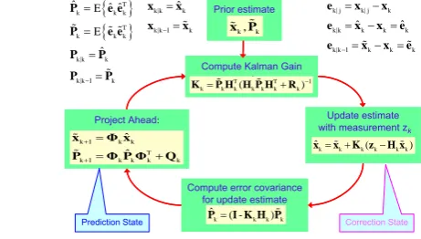
The mathematical equations and phases of the KF algorithm can be summarized as a process cycle of Kalman filtering given in Figure 1 [3], where x , ˆk x , k ek j| , e , and ˆk e are the state k
estimate matrix, state prediction matrix, state error matrix, estimation error matrix, and prediction error matrix, respectively; P , ˆk P , and Kk k are the estimation error
covariance matrix, prediction error covariance matrix, and Kalman Gain, respectively. Figure 1. The process cycle of Kalman filtering. International Archives of the Photogrammetry, Remote Sensing and Spatial Information Sciences, Volume XXXIX-B1, 2012
2.3 Location Tracking Using Alpha-Beta Filtering
An Alpha-Beta (α-β) filtering approach can be based on the steady state of the KF-based approach, which does not require repeatedly calculating the Kalman gain, and the computational complexity of the scheme is much lower than the traditional KF algorithm [6]. In this paper, using x for position and v for speed, the α-β tracking approach is expressed as follows.
Prediction step (time update)
1 ˆ ˆ
k k k kk
x x v (10)
1 ˆ
k k
v v , (11)
where
x
k andv
k
x
k are the predicted location matrix and the predicted speed matrix, respectively.Correction step (measurement update) ˆk k ( k k)
x x z x (12) ˆk k ( k)( k k)
v v z x , (13)
where x , ˆk vˆkx , and zˆk k are the estimated position matrix,
the estimated speed matrix, and the measured position matrix, respectively. The location estimator based on the α-β tracking scheme to track the location information of an MT was described in [6]. Furthermore, α and β are tuning constants between number 0 and number 1 to smooth the location and speed estimates. If 0, the measurement has no effect on the approach; if 1, the history has no effect on the approach.
2.4 Normalized Cross Correlation
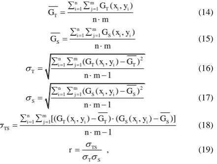
In order to recognize the reference nodes (RNs) as landmarks along the test path, this paper combines a pattern recognition method with identifications (IDs) of RNs for calibrating the location estimation. As is well known, the simplest area-based image-matching method is the NCC algorithm [10]. The NCC scheme is widely used in image-processing applications, and it can be against the brightness difference between the image and template due to lighting condition. In this paper, the useful equations of the NCC approach are as follows.
1 1 ( , )
n m
i j T i i
T
G x y G
n m
(14)
1 1 ( , )
n m
i j S i i
S
G x y G
n m
(15)
2
1 1( ( , ) )
1
n m
i j T i i T
T
G x y G
n m
(16)
2
1 1( ( , ) )
1
n m
i j S i i S
S
G x y G
n m
(17)
1 1[( ( , ) ) ( ( , ) )]
1
n m
i j T i i T S i i S
TS
G x y G G x y G
n m
(18)
TS
T S
r
, (19)
where GT(x, y) and GS(x, y) are the image mask of the grayscale
of target window and search window, respectively;GS and GT are the means of the grayscale of target window and search window, respectively; m and n are the numbers of rows and columns, respectively; T and S are the standard deviations of the image mask of the target window and search window, respectively. TSis the value of cross correlation; r is the NCC value, and it can indicate that the most likely video frame or time passes thought the landmarks.
2.5 ZigBee Positioning System (ZPS)
The ZigBee network is based on IEEE 802.15.4, which can exchange information during the route maintenance process with the features of low transfer rate, low power, and low cost. Generally, a simplified positioning system based on ZigBee network for location estimation can be illustrated in Figure 2, where the RSS indicator (RSSI) is a measurement of the power of the received radio signal. In general, this kind of ZigBee positioning system (ZPS) includes three type models (nodes): coordinator, reference node (RN), and blind node (BN). As demonstrated in Figure 2, the coordinator is directly connected to a computer; RNs placed at a known position would send device identifications (IDs) and coordinates to BNs. That is, an RN is a static node placed at a known position; a BN is a node collecting signals from all RNs responding to the respective RSSI values of RNs for location estimation. As shown in Figure 2, when a BN receives signals from neighboring RNs, the distance between the BN and RNs can be calculated by collecting the RSSI samples and path-loss model, and then the location of the BN can be obtained with well known coordinates of RNs. Afterward, the calculated location of the BN (MT) is sent to the coordinator through WSN system for LBS applications, such as asset tracking, patient monitoring, inventory control, security and commissioning networks.
Figure 2. A scenario of the ZPS scheme for estimating the BN’s location based on the RSSI information.
3. THE PROPOSED ALGORITHM
For the approaches of incorporated measurement uncertainties in WSN system, one of the popular commercial ZPSs is based on the CC2431 location engine developed by Texas Instruments (TI) [11]. The CC2431 is a hardware location engine targeting low-power ZigBee WSN applications. Furthermore, to reduce network traffic compared to infrastructure-based location systems, the location engine calculates the location of a BN with client-based deployment in a network. However, in terms of the RSSI, the TI CC2431 location engine gains X and Y International Archives of the Photogrammetry, Remote Sensing and Spatial Information Sciences, Volume XXXIX-B1, 2012
locations independently. Consequently, this paper focuses on location tracking approaches in terms of X and Y groups independently in two-dimensional (2-D) coordinate system.
3.1 ZPS Testbed
As illustrated in Figure 2, for LSB applications, the experimental investigation is implemented with CC2430/ CC2431 ZigBee wireless sensor nodes based on three main models, including coordinator, RN, and BN [11]. Furthermore, to develop an algorithm with low computational complexity in the proposed experimental testbed, the decision mode of the KF-based approach is replaced with an α-β-based approach to avoid repeatedly calculating the Kalman gain in the ZPS testbed [6]. In terms of the inherent fixed-coefficient feature of α-β filtering, the location information between the prediction phase and correction phase is efficiently cycled, thus simplifying implementation of a KF-based approach. According to the simulation results in [6], under a stationary environment, the result showed that an α-β tracking scheme not only can achieve the location accuracy close to the KF tracking scheme but has RNs (RN:1–26) denoted by circle ● are widely distributed over the roof floor. Fifteen RNs are placed in the closed-loop test trajectory. Furthermore, to measure the RSSI information more accurately, the simple antenna pattern-measurement method described in [12] was adopted. Using this technique, the BN was placed on a turntable, which could be rotated in order that the radiation antenna of the RN was directed to the north, west, south, and east directions, consecutively. The RSSI information in terms of different distances (the distance between a RN and a BN, from 1 meter to 10 meter) in the four directions was
Figure 3. The floor layout of the experimental environment.
3.3 Problem Formulation
For location-estimation techniques using tracking algorithms, KF-based approaches have been introduced to enhance the accurate estimation of the location-estimation system. As a result, to improve the location accuracy with a tracking technique for location estimation, a location tracking approach can be formulated as a filtering problem. In addition, in terms of filtering approach, although the state and measurement models are based on a 2-D model for a linear Gaussian system, the compared the equations (5) and (6) with the equations (20) and
(21), 1, 2, 3, 4, respectively. Furthermore, for the location tracking approach based on an α-β filtering, [ ]T position matrix, the predicted speed matrix, the estimated position matrix, the estimated speed matrix, and the transpose operator, respectively. Therefore, the equation relationship can be reduced from those of the KF algorithm as follows [6].
0
3.4 Location Estimation Using Vision Assisting
In a WSN system, the characteristics of signal propagation suffer from reflection, diffraction, scattering, and heavy shadow fading of the propagation effects, and then unstable RSSIs will affect the accuracy of location estimation. That is, as a CC2431 International Archives of the Photogrammetry, Remote Sensing and Spatial Information Sciences, Volume XXXIX-B1, 2012
location engine is fed with large fluctuation of RSSI information, the location accuracy will be reduced. To improve location accuracy, a simple technique employing landmark-assisted scheme is used to overcome the corner effect caused by the filtering and tracking method for dramatic time varying systems in different environmental conditions. That is, an MT (BN) can calibrate and modify its location based on sensing landmark location. In this paper, the RNs as landmarks can be extracted from video characteristics by the NCC approach for location estimation. In addition, to reduce the energy consumption and prolong the lifetime of a smartphone using the NCC approach for location estimation, the proposed scheme allows the vision-assisted concept to operate two modes based on a threshold. Two modes are the sleep mode and the active mode; the threshold is in terms of RSSIs of the ZPS testbed. As illustrated in Figure 3, if an RSSI (path loss) is smaller than the threshold, the vision-assisted algorithm will enter the active mode. That is, only the BN is close to RNs, the video camera of the smartphone starts recording the path, and then the NCC approach is carried out for landmark detection. On the contrast, when an RSSI is larger than the threshold, the vision-assisted algorithm will enter the sleep mode, and the video camera stops recording the path. Figure 4 indicates a simple example about the vision-assisted scheme based on NCC approach. The experimental result demonstrates that an RN can be extracted and detected from video characteristics by the NCC approach as a landmark correctly.
0.31200 1250 1300 1350 1400 1450 1500 1550 1600 0.4
0.5 0.6 0.7 0.8 0.9 1 1
Number of frame
r
NCC
Figure 4. An example of an RN treated as a landmark extracted from an image with the NCC approach.
4. EXPERIMENTAL RESULTS
4.1 ZigBee Positioning System
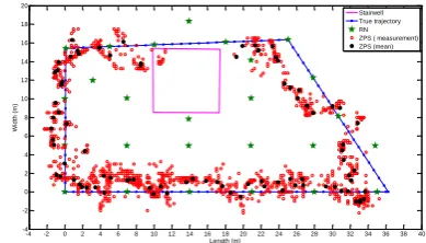
In this paper, the experimental investigation combines CC2430/ CC2431 ZPS platform with vision-assisted approach for location estimation and tracking. As an MT moved along the test path in Figure 3, the experimental results of location estimation using the TI ZPS testbed are illustrated in Figure 5, where the location estimations are denoted by red hollow circles. In addition, as an MT locates at sample locations in Figure 3, the mean of the location estimation is denoted by black solid circles in Figure 5. To verify the performances of estimation results introduced by the proposed schemes, the location parameters are based on the estimation result from TI ZPS testbed in Figure 5. Without loss of generality, it is assumed that the MT has a steady speed in (20); k, the measurement interval (sampling time) between k and k+1, are set to one second. In addition, the model describing the observation location of the MT taken in (21) is based on Figure 5.
4.2 Location Estimation Using Kalman Filtering
The location results in terms of the cumulative distribution function (CDF) of the error distance of the KF tracking method
are given in Figure 6(a). The results demonstrate that more than 60 percent of the estimated locations with the ZPS scheme has error distances less than 2.20 meters; more than 60 percent of the estimated locations with the KF-based scheme has error distances less than 1.80 meters. According to the experimental results in Figure 6, the location accuracy of the KF tracking algorithm is better than the ZPS method. In other words, the KF-based approach can diminish the estimated errors compared with ZPS method. In fact, the property of the KF-based method is a recursive minimum mean-squares state algorithm, so the location error of KF tracing algorithm can be considered as a good upper CDF bound for other location estimators.
-4 -2 0 2 4 6 8 10 12 14 16 18 20 22 24 26 28 30 32 34 36 38 40 -4
-2 0 2 4 6 8 10 12 14 16 18 20
Length (m)
W
id
th
(m
)
Stairwell True trajectory RN ZPS ( measurement) ZPS (mean)
Figure 5. Results for the location estimation using TI ZPS platform as an MT(BN) move along the test path.
4.3 Location Estimation Using Alpha-Beta Filtering
As described previously, according to KF tracking approach and (22), the coefficients of the α-β tracking approach can be obtained. In terms of the experimental result in Figure 6(a), it indicates the comparison between the KF and the α-β tracking methods, too. From the experimental results, the location accuracy of the α-β tracking approach based on the coefficients of the Kalman gain is almost the same location accuracy as the KF tracking approach. In fact, the results demonstrate that more than 60 percent of the estimated locations using the α-β tracking approach has error distances less than 1.85 meters. However, if
0.5
, this means that the measurement and the history have effects. According to the result in Figure 6(a), while α and β are set to 0.5, the α-β tracking approach has error distances less than 1.95 meters; the location accuracy still shows a slight improvement for ZPS method. In short, as compared with the KF tracking scheme, the α-β tracking scheme can achieve acceptable location performance and can gain a lower computational burden.
4.4 Location Estimation Using Vision Assisting
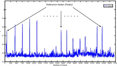
According to the experimental results, the threshold of RSSIs (path loss) of the ZPS testbed is set to 60 dBmW in this paper. As illustrated in Figure 3, if an RSSI is smal1er than 60 dBmW, the vision-assisted algorithm will enter the active mode. On the contrast, when an RSSI is larger than 60 dBmW, the vision-assisted algorithm will enter the sleep mode. Figure 7 indicates the experimental results using vision-assisted scheme based on NCC approach. The results illustrate that the RNs can be detected as landmarks correctly. In terms of the CDF of the error distances, Figure 6(b) shown the comparison between the KF and the α-β tracking schemes using the vision-assisted approaches based on NCC approach. The results demonstrate that more than 60 percent of the estimated locations using the KF-based and α-β-based approaches have error distances less International Archives of the Photogrammetry, Remote Sensing and Spatial Information Sciences, Volume XXXIX-B1, 2012
than 1.40 meters. In addition, as α and β are set to 0.5, the result demonstrates that more than 60 percent of the estimated locations using the α-β tracking approach have error distances less than 1.55 meters. In brief, Figure 6 indicates the comparison among the ZPS, KF-based, and the α-β-based approaches without and with the vision-assisted methods as an MT moves along a test path. In Figure 6(b), after using vision assistance, the experimental results illustrate that the location accuracies of the proposed positioning methods are better than the non-vision assisted positioning methods. The results also show that the proposed vision-assisted scheme can provide a environments of the path more efficiently.
0 0.5 1 1.5 2 2.5 3 3.5 4 approaches in terms of the CDF of the error distances.
0 250 500 750 1000 12501500 17502000 22502500 27503000 32503500 37504000 425045004750 0.4
Figure 7. The image-matching results of RNs based on the NCC approach as an MT (BN) move along the test path.
5. CONCLUSION
In this paper, we have presented a reduced-complexity location-estimation testbed based on an α-β filtering algorithm for location tracking. For the purpose of increasing the execution speed, the conventional KF algorithm may not be suitable for practical implementation due to its high computational complexity, especially in location-estimation systems with large computational problem. According to the proposed testbed, the coefficients of the α-β filter are extracted from the KF algorithm, which is a degenerate form of the KF algorithm. As compared with the conventional KF-based approach, the α-β-based
approach is much lower computational complexity. In addition, the landmark extracted from video vision characteristics is based on NCC procedures. In terms of vision-assisted approach to extract the locations of RNs as landmarks, the α-β tracking scheme with the RN information can calibrate the location estimation and alleviate the corner effect. Under a stationary environment, according to the experimental results about investigating and comparing the performance of the KF and α-β tracking algorithms, we conclude that the proposed scheme demonstrates much better accuracy as compared with the non-tracking algorithm and without vision-assisted approach; it also demonstrates much lower computational complexity with comparable accuracy as compared with the conventional optimal KF algorithm. With the good features of location accuracy and computational complexity, the proposed location-tracking platform combining vision-assisted scheme with α-β tracking approach in ZPS of WSNs is attractive for use in various LBS systems.
ACKNOWLEDGEMENT
This work was supported in part by the National Science Council of the Republic of China under grant NSC 98-2221-E-008-097-MY2.
REFERENCES
[1] Bellavista, P., Kupper, A. and Hela, S., 2008. Location-based services: Back to the future. IEEE Perva sive Comput., Vol. 7, No. 2, pp. 85–89.
[2] Moon, T. K. and Stirling, W.C., 2000. Ma thematical Mthods and
Algorithms for Signal Processing. Prentice Hall, New Jersey.
[3] Chiou, Y.-S., Wang, C.-L. and Yeh, S.-C., 2010. An adaptive location estimator using tracking algorithms for indoor WLANs.
ACM/Springer Wireless Netw., Vol. 16, No. 7, pp. 1987–2012.
[4] Fischer, C. and Gellersen, H., 2010. Location and navigation support for emergency responders: A survey. IEEE Perva sive Comput., Vol. 9, No. 1, pp. 38–47.
[5] Rhee, I., Abdel-Hafez, M. F. and Speyer, J. L., 2004. Fixed-lag alpha-beta filter for target trajectory. IEEE Trans. Aerospace and
Electronic Systems, Vol. 40, No. 4, pp. 1417–1421.
[6] Chiou, Y.-S., Wang, C.-L. and Yeh, S.-C., 2011. Reduced-complexity scheme using alpha-beta filtering for location tracking.
IET Commun., Vol. 5, No. 13, pp. 1806–1813.
[7] Zheng P. and Ni, L. M., 2006. The Rise of the Smart Phone. IEEE
Distributed Systems Online, Vol. 7, No. 3, art. No. 0603-o3003.
[8] Kim, Y., Chon, Y. and Cha, H., 2012. Smartphone-based collaborative and autonomous radio fingerprinting. IEEE Trans. Syst., Ma n, Cybern. C, Appl. Rev., Vol. 42, No. 1, pp. 112–122. [9] Bishop, C. M., 2006. Pattern Recognition and Ma chine Learning.
Springer, Cambridge.
[10] Wolf, P. R. and Dewitt, B. A., 2000. Elements of Photogrammetry
with Applications in GIS. McGraw-Hill, Taipei.
[11] CC2431 Location engine. http://www.ti.com/product/cc2431 (Mar. 2012)
[12] Chiou, Y.-S., Wang, C.-L. and Yeh, S.-C., 2005. An indoor location scheme based on wireless local area networks. In: IEEE
Consumer Communications and Networking Conference, Las
Vegas, USA, pp. 602–604.