Planar Constraints for an Improved UAV-image-based Dense Point Cloud Generation
F. He a, *1, A. Habib a, A. Al-Rawabdehb
a Lyles School of Civil Engineering
Purdue University, 550 Stadium Mall Dr., West Lafayette, IN 47907, USA – (he270, ahabib)@purdue.edu
b Department of Geomatics Engineering
University of Calgary, 2500 University Dr. NW, Calgary, AB T2N 1N4, Canada – [email protected]
Commission I, WG I/3
KEY WORDS: Image Matching, Dense Point Cloud, UAV Images, Segmentation
ABSTRACT:
In this paper, we proposed a new refinement procedure for the semi-global dense image matching. In order to remove outliers and improve the disparity image derived from the semi-global algorithm, both the local smoothness constraint and point cloud segments are utilized. Compared with current refinement technique, which usually assumes the correspondences between planar surfaces and 2D image segments, our proposed approach can effectively deal with object with both planar and curved surfaces. Meanwhile, since 3D point clouds contain more precise geometric information regarding to the reconstructed objects, the planar surfaces identified in our approach can be more accurate. In order to illustrate the feasibility of our approach, several experimental tests are conducted on both Middlebury test and real UAV-image datasets. The results demonstrate that our approach has a good performance on improving the quality of the derived dense image-based point cloud.
1. INTRODUCTION
The availability of high-accuracy dense point clouds is of increasing importance for scientists and researchers interested in 3D reconstruction of the environment. In general, 3D reconstruction can be achieved through either passive or active remote sensing systems. Active systems, which could directly capture precise, and reliable 3D measurements of objects, has become a standard source for 3D reconstruction in current applications. However, the utilization of such technique usually requires significant initial investment for the acquisition of active sensors, especially when seeking high level of reconstruction accuracy. Therefore, passive remote sensing systems, which commonly use digital frame cameras, are still the most complete, economical, flexible, widely used 3D reconstruction option (Remondino and El-Hakim, 2006).
In conventional photogrammetric research communities, 3D reconstruction from digital images captured by passive sensors requires the knowledge of the Interior Orientation Parameters (IOP) of the utilized camera, the Exterior Orientation Parameters (EOP) of the involved images, and the corresponding points/features in the set of overlapping images. The IOP of the utilized camera can be derived from a camera calibration process. The EOP of the involved imagery can be either derived through an indirect geo-referencing procedure using tie and control points or a direct geo-referencing process through the implementation of a GNSS/INS unit on-board the mapping platform. While the latter approach provides practical convenience in terms of simplifying the geo-referencing process, it requires significant initial investment for the acquisition of the high-end GNSS/INS Position and Orientation System (POS) – especially, when seeking high level of reconstruction accuracy. Instead of using the conventional photogrammetric reconstruction technique, lots
* Corresponding author. This is useful to know for communication with
the appropriate person in cases with more than one author.
of research efforts have been exerted towards the Unmanned Aerial Vehicle (UAV)-based 3D reconstruction. In these research, the utilization of Structure from Motion (SfM) approach and dense image matching technique has been investigated. To be specific, the SfM approach, which is initiated by the computer vision research communities, automates the process of EOP recovery. The dense image matching technique provides pixel-based matching results. Compared to the conventional photogrammetric approach, current UAV-based 3D reconstruction is more advantageous, since it allows for 3D dense point cloud generation in the absence of GNSS/INS units.
It is important to note that although state-of-the-art dense image matching technique provides accurate pixel-wise matching results, the resulting disparity image, which encodes the x-parallax at each pixel, can still contain some errors. Therefore, this research is dealing with a new disparity refinement procedure for the UAV-image-based dense point cloud generation. More specifically, the local smoothness constraint and point cloud segments are utilized to improve the disparity image that are derived from dense image matching. The remainder of the paper presents the proposed approach in more details. First, a literature review of related work is given. Then, the proposed methodology is introduced. Afterwards, experimental results are discussed. Finally, the drawn conclusions and recommendations for future work are presented.
2. RELATED WORK
Current dense image matching algorithms can provide matching results for each image pixel. A detailed comparison of dense image matching algorithms has been conducted by Scharstein and Szeliski (2002). In their paper, the dense image matching
algorithms are assumed to be composed of four steps. These four steps includes matching cost computation, cost aggregation, disparity optimization, and disparity refinement. Then, existing algorithms are classified into different categories as modification in one or more steps.
Among the above-mentioned four steps in dense image matching, the improvement of disparity optimization attracts great interest from researchers. As far as the disparity optimization is concerned, two different approaches can be adopted. In the first approach, a local disparity optimization is applied, where best matching pixels are usually found using a Winner-takes-all (WTA) strategy. However, WTA fails in image matching with uniform areas. Alternatively, the latest dense image matching techniques usually adopt a 2-dimensional (either global or semi-global) approach for the disparity optimization. For global dense image matching, several powerful global optimization methods have been adopted. For example, Dynamic Programming (Forstmann et al., 2004), Graph-Cut-based (Boykov et al., 2001) and Belief-Propagation-based (Sun et al., 2003) approaches are three most widely used global optimization methods. However, all these approaches are quite computationally expensive. The semi-global dense matching algorithm (Hirschmuller, 2005, 2008) is a relatively new stereo dense image matching technique. It minimizes the image matching costs along several 1D directions through the image, and offers a very good trade-off between matching accuracy and computational-efficiency. Therefore, several research efforts have been conducted on the semi-global dense matching algorithm. Gerke in 2009 demonstrated the power of semi-global dense image matching when using oblique aerial images of urban scenes. Hirschmüller and Bucher in 2010 compared the digital surface models (DSMs) derived from the semi-global dense matching algorithm with DSMs from a laser model and ground control points (GCPs). They concluded that very precise DSMs can be derived from dense image matching, especially using datasets with sufficient image overlap. Some other researchers (Gehrke et al., 2010; Geiger et al., 2011) also demonstrated that semi-global dense matching algorithm has superior performance when compared to other matching methods and laser scanning systems. These research efforts demonstrate that the semi-global dense matching method is useful for solving various practical problems that require high density surface models.
As stated above, matching results derived from different algorithms can still contain some errors. In order to remove these outliers, additional geometric constraints are usually enforced in the matching algorithm to refine the obtained disparity values. For example, one commonly used assumption is that the object surfaces are piece-wise planar. In order to model such assumption, several methods (Wang and Zheng, 2008; Humenberger et al., 2010) take advantage of color-based image segmentation, and enforce plane representation in each image segment. However, the main disadvantage of these methods is that the obtained image segments do not always correspond to a planar surface in real world.
3. METHODOLOGY
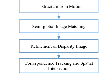
In this paper, a new disparity refinement procedure is proposed for the improvement of dense UAV-image-based point cloud generation. Figure 1 illustrates the workflow of the proposed procedure. First, a Structure-from-Motion (SfM) approach developed by He and Habib (2014) is adopted for the estimation of image EOPs. Then, the semi-global dense image matching algorithm is implemented for dense point cloud generation.
Afterwards, local smoothness constraint and point cloud segments are utilized to improve the disparity image that are derived from the semi-global dense image matching. Finally, correspondence tracking and spatial intersection are applied to generate dense image-based point cloud using the refined disparity images.
Figure 1. The workflow of the proposed UAV-image-based dense point cloud generation process
3.1 Structure from Motion
Image-based point cloud generation requires the availability of accurate IOPs of the utilized camera, the EOPs of the involved images, and the corresponding pixels/features in the set of overlapping images. The IOPs of the utilized camera can be derived from a camera calibration process. In order to derive the EOPs of the involved images, the SfM approach, which automates feature matching and EOP recovery, is adopted. The utilized SfM approach is developed by He and Habib (2014), and it is based on a three-step strategy for the recovery of the image EOPs. In the first step, the relative orientation parameters (ROPs) relating stereo-images are initially computed from the automatically identified SIFT features. In the second step, a local reference coordinate frame is first established. Then, the EOPs of the remaining images are sequentially recovered through an incremental augmentation process. Finally, in the third step, a bundle adjustment process is carried out to refine the derived information in the second step.
3.2 Semi-global Image Matching
From camera calibration and the utilized SfM approach, we can derive the IOPs of the camera and the EOPs of the involved images. Then, the epipolar geometry within the available image stereo-pairs can be reconstructed. The benefit of the epipolar geometry is that the search for corresponding points need not cover the whole image plane, but rather can be restricted to the epipolar line. Such epipolar geometry enables a much easier process for dense image matching. In this paper, the semi-global dense matching algorithm, which searches the matching pixels along the epipolar line, is implemented.
Different from other dense image matching algorithms, the novel idea of the semi-global dense matching is that the optimization of disparity values is achieved through a semi-global approach. As shown in Figure 2, the semi-global image matching minimizes the global energy along several 1D directions (horizontal, vertical, and diagonal) through the image. The minimum cost path
, , � of pixel , at disparity d along direction r (see Figure 2b) is defined recursively as in Equation 1.
Structure from Motion
Semi-global Image Matching
Refinement of Disparity Image
Correspondence Tracking and Spatial Intersection
, , � = , , � + min ′, ′, � ,
′, ′, � − + ,
′, ′, � + + ,
min ′, ′, � + (1)
In this equation, pixel ( ′, ′ is the neighbouring pixel of pixel , along direction r. , , � represents the matching cost of pixel , at disparity d. P1 and P2 are two constant penalty values used to enforce the smoothness constraint among neighbouring pixels. In the semi-global optimization, small penalty P1 is added if the disparity change of the neighbouring pixels is relatively small (i.e., one pixel), and large penalty P2 is added if the disparities differ by more than one pixel within the neighbourhood. Once the minimum cost path is determined at each direction, the aggregated costs S can be derived by summing up all the minimum cost paths in all directions (see Equation 2). Then, for each pixel, the disparity with the lowest aggregated costs S can be selected as the initial disparity. As a result, semi-global dense matching optimizes the disparity value at each pixel with the optimal paths through the whole image.
S , , � = ∑ , , �
(2)
Figure 2. (a) Semi-global optimization, and (b) Minimum cost path
3.3 Refinement of Disparity Image
Although the semi-global dense matching algorithm provides accurate pixel-wise matching results, the resulting disparity image, which encodes the x-parallax at each pixel, can still contain some errors. In this paper, the local smoothness constraint and point cloud segments are utilized to improve the disparity image derived from the semi-global algorithm. Before introducing the proposed methods, the disparity-to-spatial relationship, which is the basis of the local-smoothness-constraint-based and the image-segments-based methods, is presented.
3.3.1 Disparity-to-spatial relationship for planar objects
As shown in Figure 3, Π is a piece of planar surface in the object coefficient represents the distance from the origin of the local frame to the plane. Using simple algebraic manipulation, it is easy to prove that the corresponding disparity model Δ of surface Π in the disparity image is linear, and the equation of the corresponding disparity model Δ can be also defined by the plane in Equation 4.
+ + � + = (4)
Where (x, y) is an image projection from point P; d is the disparity value at image point (x, y), and , , , �� are the coefficients of the disparity plane. In addition, if the baseline length of the pair is L, and the focal length of the normalized stereo-image is f, the mapping between the object surface and the disparity plane can be established as Equation 5.
{
Figure 3. Disparity-to-spatial relationship for planar objects
3.3.2 Refinement Using Smoothness Constraint
In practice, it is common to assume that the object surface is piece-wise smooth. Considering the relationship between the planar object and the disparity plane, which was previously explained, it is also reasonable to assume that the resulting disparity field corresponding to the object surface is piece-wise smooth. In this context, the local smoothness constraint, which assumes the local smoothness in the disparity image, can be enforced to eliminate the outliers in the disparity image. The proposed method of the local smoothness constraint can be achieved in two steps.
In the first step, the disparity-based normal vector is estimated at each pixel in the disparity image. In the disparity image, a local window is first used to define the surrounding neighbourhood at each pixel. Then, the disparity-based normal vector of the pixel cantered at the pre-defined local window is estimated through an eigenvalue analysis (Lari and Habib, 2013). In the second step, a local disparity-normal-vector-based analysis is carried out to eliminate the outliers in the disparity image. A smoothness threshold (��) in terms of the angle among the estimated disparity-based normal vectors within the local window is first defined. Then, to eliminate outliers, the sum of the dot product of two normal vectors is computed.
∑‖� ∙ ��‖ �
�=0
(7)
Where � is the disparity-based normal vector of central pixel , and �� is the disparity-based normal vector of neighbouring pixel �. Thus, if ∑ ‖� ∙ ���=0 �‖< ∙ cos �� , where M and N are the size of the predefined local window, we consider central pixel to comply with the local smoothness constraint, and it can be kept as a valid pixel in the disparity image; otherwise, pixel is labelled as an outlier, and eliminated from the disparity image.
3.3.3 Refinement Using Point Cloud Segments
The second approach for disparity refinement assumes correspondences between the point cloud segments and the planar surfaces in the object space. Instead of using 2D-image segmentation algorithms, such as Mean Shift Segmentation, we identified planar surfaces from the given point cloud (e.g., either the derived sparse point cloud from SfM approach or derived point cloud from initial semi-global dense matching) through a 3D point cloud segmentation. In this paper, the adopted point cloud segmentation is developed by (Lari et al., 2011). Since 3D point clouds include more geometric information regarding the reconstructed objects, segments derived from point cloud segmentation are more accurate. Then, the boundary of the identified planar segments are back-projected onto corresponding images. Finally, a plane fitting within the disparity space similar to the one suggested by Wang and Zheng (2008), is applied within each back-projected segment to refine the obtained disparity values.
3.4 Correspondences Tracking and Spatial Intersection
Once the refined disparity image is obtained, correspondences tracking and multiple light ray intersection are carried out for dense point cloud generation. Two filters are incorporated in the multiple light ray intersection process. The first filter is used to remove blunders or outliers. In this research, if the average image residuals obtained from the spatial intersection are larger than a certain threshold, the image points are discarded as blunders. The second filter is used to remove the points with low intersection precision. In this research, the second filter is implemented by ensuring that a tracked point should appear in at least three images.
4. EXPERIMENTAL RESULTS
To illustrate the feasibility of the proposed procedure, we conducted several tests on both Middlebury and real-world image datasets.
4.1 Middleburry Dataset
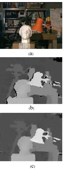
The Middlebury dataset provides benchmarking images for the evaluation of stereo matching algorithms. In the experimental test, the derived disparity image is compared with the ground truth. In order to identify the planar surfaces in object space, we utilized the derived point cloud from initial semi-global dense matching for point cloud segmentation. Table 1 shows the achieved improvement on semi-global dense matching. Figure 4 illustrates the derived disparity images from the proposed approach.
Table 1. The percentage of correctly matched pixels of the implemented semi-global dense matching (SGM) before and
after applying the proposed refinement
SGM SGM + Refinement
87.1% 90.3%
Figure 4. Middlebury Tsukuba Dataset: (a) original left image, (b) disparity image from the implemented semi-global dense matching and (c) disparity image after applying the proposed
refinement.
4.2 Real Dataset
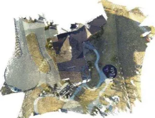
The Middlebury dataset gives a good idea of the matching quality compared with the ground truth data. However, these image are created under very well controlled conditions, which is almost impossible in the real-world data collection. Therefore, the performance of the proposed approach is evaluated on a real UAV image dataset. The utilized UAV images were captured by a DJI Phantom 2 UAV with a GoPro 3 camera. The GoPro camera has been calibrated (He and Habib, 2015), and the normalized UAV images are generated for dense image matching. Figure 5 illustrates a sample of the derived disparity image on the UAV image dataset. Meanwhile, the UAV-image-based dense point cloud is generated on this dataset. The derived point cloud is shown in Figure 6. In order to compare the reconstructed dense point clouds before and after applying the proposed approach, profiles across the dense point clouds are generated and displayed in Figure 7. From these results, we can note that the derived disparity images are effectively improved by applying the proposed approach.
(
a
)(
b
)(
c
)Figure 5. Result from the UAV-image dataset: (a) original left image, (b) original right image, (c) normalized left image, (d) normalized right image, (e) disparity image derived from the implemented semi-global dense matching, and (d) refined
disparity image by applying the proposed approach, the improved area is highlighted with the red circle.
Figure 6. Dense image-based point cloud derived from the UAV image dataset after applying the proposed disparity refinement
Figure 7. A profile of the reconstructed dense point cloud before (red color) and after (green color) applying the proposed
disparity refinement
5. CONCLUSIONS AND RECOMMENDATISONS FOR FUTURE WORK
5.1 Conclusions
In this paper, we proposed a new refinement procedure for the semi-global dense matching algorithm. The experimental results demonstrate that the proposed approach has the following characteristics:
1. Both smoothness constraint and point cloud segments are utilized for the refinement of disparity images. A combination of these two different approaches can effectively deal with real scenes containing both planar and curved surfaces.
2. Compared with the refinement using image-based segments, segments derived from 3D point clouds are more accurate, since 3D point clouds include more precise geometric information regarding the reconstructed objects.
5.2 Recommendations for Future Work
It is important to note that the proposed approach is just a successive refinement on the derived disparity images. However, it is much better to incorporate these planar constraints (both smoothness and segment-based constraints) into the disparity optimization process. For future work, enforcing planar constraints at the disparity optimization process will be investigated.
REFERENCES
Boykov, Y., Veksler, O., Zabih, R., 2001. Fast approximate energy minimization via graph cuts. Pattern Anal. Mach. Intell. IEEE Trans. On 23, 1222–1239. Forstmann, S., Kanou, Y., Ohya, J., Thuering, S., Schmitt, A.,
2004. Real-time stereo by using dynamic programming, in: Computer Vision and Pattern Recognition Workshop, 2004. CVPRW’04. Conference on. IEEE, pp. 29–29.
Gehrke, S., Morin, K., Downey, M., Boehrer, N., Fuchs, T., 2010. Semi-global matching: An alternative to LIDAR for DSM generation, in: Proceedings of the 2010 Canadian Geomatics Conference and Symposium of Commission I.
Geiger, A., Roser, M., Urtasun, R., 2011. Efficient large-scale stereo matching, in: Computer Vision–ACCV 2010. Springer, pp. 25–38.
Gerke, M., 2009. Dense matching in high resolution oblique airborne images. Int. Arch. Photogramm. Remote Sens. Spat. Inf. Sci. 38, W4.
He, F., Habib, A., 2015. Target-based and Feature-based Calibration of Low-cost Digital Cameras with Large Field-of-view. Presented at the ASPRS 2015 Annual Conference, Tampa, Florida.
He, F., Habib, A., 2014. Linear Approach for Initial Recovery of the Exterior Orientation Parameters of Randomly Captured Images by Low-Cost Mobile Mapping Systems. ISPRS-Int. Arch. Photogramm. Remote Sens. Spat. Inf. Sci. 1, 149–154.
Hirschmuller, H., 2008. Stereo processing by semiglobal matching and mutual information. Pattern Anal. Mach. Intell. IEEE Trans. On 30, 328–341.
Hirschmuller, H., 2005. Accurate and efficient stereo processing by semi-global matching and mutual information, in: Computer Vision and Pattern Recognition, 2005. CVPR 2005. IEEE Computer Society Conference on. IEEE, pp. 807–814.
(
a
) (b
)(
c
) (d
)(
e
) (f
)Hirschmüller, H., Bucher, T., 2010. Evaluation of digital surface models by semi-global matching. DGPF Tagungsband 19, 571–580.
Humenberger, M., Engelke, T., Kubinger, W., 2010. A census-based stereo vision algorithm using modified semi-global matching and plane fitting to improve matching quality, in: Computer Vision and Pattern Recognition Workshops (CVPRW), 2010 IEEE Computer Society Conference on. IEEE, pp. 77–84.
Lari, Z., Habib, A., 2013. A novel hybrid approach for the extraction of linear/cylindrical features from laser scanning data. ISPRS Ann Photogramm Remote Sens Spat. Inf Sci 2, 151–156.
Lari, Z., Habib, A., Kwak, E., 2011. An adaptive approach for segmentation of 3D laser point cloud, in: ISPRS Workshop Laser Scanning. pp. 29–31.
Scharstein, D., Szeliski, R., 2002. A taxonomy and evaluation of dense two-frame stereo correspondence algorithms. Int. J. Comput. Vis. 47, 7–42.
Sun, J., Zheng, N.-N., Shum, H.-Y., 2003. Stereo matching using belief propagation. Pattern Anal. Mach. Intell. IEEE Trans. On 25, 787–800.
Wang, Z.-F., Zheng, Z.-G., 2008. A region based stereo matching algorithm using cooperative optimization, in: Computer Vision and Pattern Recognition, 2008. CVPR 2008. IEEE Conference on. IEEE, pp. 1–8.