STRUCTURAL DESIGN OF ABUTMENT USING GEO 5 PROGRAM
Final Project
In partial fulfillment for the award of
Bachelor of Engineering Degree in Civil Engineering
Prepared by :
ABDULRAHMAN YASIN HUSEN NIM :
D 100 122 013
CIVIL ENGINEERING DEPARTMENT
ENGINEERING FACULTY
UNIVERSITAS MUHAMMADIYAH SURAKARTA
PREFACE
Assalamu’alaikum Wr. Wb.
Alhamdulillah, all praise to Allah azza wa jalla who has given blessing and mercies until this Final Project can be completed. This Final Project to complete most the requirement to achieve S-1 graduate degree in Civil Engineering Department, Engineering Faculty, Universitas Muhammadiyah Surakarta. The author also says thanks for all parties who give any support for arrangement this Final Project until it can be completed.
The accomplishment this Final Project the author will say thanks to other parties :
1) Sri Sunarjono,PhD as the Dean of Engineering Faculty of Universitas Muhammadiyah Surakarta.
2) Mohammad Solikin,PhD as Head of Civil Engineering Department of Universitas Muhammadiyah Surakarta.
3) Muslich Hartadi.PhD as author’s academic advisor who has given many suggestion for author’s academic.
4) Anto Budi Listyawan,S.T,M.Sc. as major advisor who has guided and taught the author.
5) Yenny Nurchasanah, S.T., M.T. as secondary advisor major advisor who has guided and taught the author.
6) Agus Susanto,S.T,M.T. as examiner who has given some advices to make this final project better.
7) All lecturers in Civil Engineering Department of Engineering Faculty of Universitas Muhammadiyah Surakarta thanks for your guidance and knowledge. 8) Dad, mom and my beloved family who always give me support. Thanks for your
vi
MOTTO
“And whenever you give your word, say the truth” (al-An`aam 6:152)
“The only way to have the greatest work in your life is love what you do first”
(Anonim)
“You are creator for your own future “
(Anonim)
“Idza shodaqol ‘azmu wadhohas sabil”
(Mahfudzot)
“Do your own thinking independently Be the chess player, not the chess piece”
(Anonim)
“Make up one idea. Make that idea on your life – think of it, dream of it, live on that idea.
Let the brain, muscles, nerves, every part of your body, be full of that idea,
and just leave every other idea alone. This is the way to success.
ix
TABLE OF CONTENT
FINAL PROJECT TITLE………...i
CERTIFICATION SHEET……...……….ii
PREFACE……….………..iii
DECLARATION OF AUTHORSHIP………..v
MOTTO………...vi
ACKNOWLEDGEMENT………vii
TABLE OF CONTENT..………...ix
LIST OF FIGURE……….………..xiii
LIST OF TABLE.………..xv
LIST OF NOTATION…...………..xvi
ABSTRACTION…..………..………xviii
CHAPTER I INTRODUCTION A. Background of The Research……….………..1
B. Statement of The Research……….………..1
C. The Research Objectives……….……….2
D. Benefit of The Research……….……..2
E. Limitation of The Research……….…….2
F. The Originality of The Research……….…….3
CHAPTER II LITERATURE REVIEW A. Bridge…….………..…...4
1. History of bridge……….………..……4
2. Types of bridges………..…..4
3. Aesthetics……….………..…...8
ix
5. Bridge failures………...9
B. Abutment……….10
1. Use of abutments………10 2. Types of abutment………..10 3. Selection of abutment……….11 4. Limit states……….12 C. Geo 5 program………..………...13 1. Main features of Geo 5 v 13 program……...……….………….13
2. The function of Geo 5 program v 13………..14
3. The benefit of Geo 5 program v 13………14
CHAPTER III THEORORITICAL REVIEWS A. Lateral earth pressure………16 1. Lateral earth pressure at rest….………17 2. Rankine active earth pressure………23
3. Coulomb theory………...………..28
B. Stability of abutment………...………..29
1. Check for overturning………...29
2. Check for sliding along the base………...31
C. Structure design reinforcement of abutment….………35
1. Reinforcement plate in one way………35
2. The calculation of reinforcement of abutment……….38
D. Introduction of Geo 5 v13 program………….……….40
1. Recognizing Geo 5 v13...………..40
2. The function of Geo 5……….…..40
3. The formula used in the program Geo 5………...41
4. The steps of using Geo 5 program..………..43
ix
B. Research Data………51
C. Research Tool………51 1. Geo 5 v13………...………...51
2. Drawing Program (Auto CAD 2015)………51
3. Microsoft Office (Office 2010)……….51
D. Research Step………51
E. Implementation……….54
CHAPTER V ANALYSIS AND DISCUSSION A. Getting the soil data………..56
B. Analysis of abutment by manual calculation……..…………..56
1. The determining of early dimension of abutment…...57
2. The calculation of lateral earth pressure………...57
3. Stability of abutment……….……….…...58
4. Calculation of reinforcement of abutment.…………...60
C. Analysis the abutment by Geo 5 program.………72
D. Discussion………...102
CHAPTER IV CONCLUSION AND SUGGESTION A. Conclusion……….105
B. Suggestion………..………106 REFERENCE
xv
LIST OF TABLE
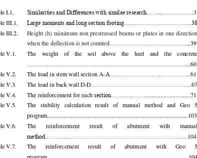
Table I.1. Similarities and Differences with similae research……..……….3
Table III.1. Large moments and long section footing…..………...38
Table III.2. Height (h) minimum non prestressed beams or plates in one direction when the deflection is not counted………..………....39
Table V.1. The weight of the soil above the heel and the concrete ……….………....60
Table V.2. The load in stem wall section A-A….…...………...…………...61
Table V.3. The load in back wall D-D………...67
Table V.4. The reinforcement for each section…….….……...71
Table V.5. The stability calculation result of manual method and Geo 5 program...103
Table V.6. The reinforcement result of abutment with manual method………....………...…104
xiv
LIST OF FIGURE
Figure II.1. Beam bridge………....………...…5
Figure II.2. Truss bridge….………..6
Figure II.3. Cantilever bridge………...6
Figure II.4. Arch bridge………6
Figure II.5. Tied arch bridge……….7
Figure II.6. Suspension bridge………..7
Figure II.7. Cable stayed bridge………....8
Figure II.8. U abutment………..10
Figure II.9. Cantilever abutment……….11
Figure III.1. Nature of lateral earth pressure on a retaining wall …..……...16
Figure III.2. Nature of variation of lateral earth pressure at a certain depth……....17
Figure III.3. At-rest earth pressure………...18
Figure III.4. Stress history for soil under �� condition………...….20
Figure III.5. At-rest earth pressure………...21
Figure III.6. Rankine active pressure………...23
Figure III.7. Assumed active pressure diagram for clay backfill behind an abutment………..26
Figure III.8. Notations for active pressure-equations (19, 20, and 21)………27
Figure III.9. Check for overturning: assume that Rankine pressure is valid………30
Figure III.10. Check for sliding along the base………..32
Figure III.11. Abutment with sloped heel………...34
Figure III.12. Variation of A with friction angle of backfill [equation (14)]……….35
Figure III.13. Cantilever with reinforcement plate’s principal one direction………36
Figure III.14. Abutment icon in start of desktop……….………...43
xiv
Figure III.17. The dimension and the type of Abutment………44
Figure III.18. Abutments wings……….45 Figure III.19. The geometric and plane bottom of abutment………..…………..…...45
Figure III.20. The concrete material’s……….………..……….46 Figure III.21. The profile assignment……….46
Figure III.22. The soil charateristics….………..47
Figure III.23. The load-LC assignment………..47
Figure III.24. The Assign………..……….48
Figure III.25. The Terrain………...………48
Figure III.26. The surcharge………...………49
Figure III.27. The soil profile in front of wall restraint soil……….………..49
Figure III.28. Analyzing the abutment stability and dimension of abutment………50
Figure III.29. Showing the result calculation abutment……….50
Figure IV.1. Flow chart of the planning stage………...53
Figure IV.2. Part of program flow Geo 5………...55
Figure V.1. Abutment applying forces diagram….………57
Figure V.2. Stem wall applying forces diagram section A-A……….60
Figure V.3. Bearing pressure under abutment footing ………...62
Figure V.4. Back wall applying forces diagram ………66
Figure V.5. Wings abutment applying forces diagram..……….68
Figure V.6. Abutment typical section design and Wing wall reinforcing …...71
Figure V.7. The icon of Abutment in start……….……….72
Figure V.8. The viewing of program when it start ………...73
Figure V.9. The project viewing………...…………...74
Figure V.10. Chose concrete design constructions and pressure analysis setting………..………….75
Figure V.11. The diagram of Abutment……...……….76
xiv
Figure V.13. The diagram of wings..………78
Figure V.14. The dimension of wings of abutment and the type the wings ...…….79
Figure V.15. Dimension scale of Abutment………..………...80
Figure V.16. Input the dimension abutment ………80
Figure V.17. The material of structure of abutment..……….81
Figure V.18. Input the weight of wall and choose the material ………..….82
Figure V.19. The viewing of profile……….………83
Figure V.20. The viewing of soils………...……….84
Figure V.21. Input dialog box of soil parameter……….………..85
Figure V.22. The viewing of load-LC………..86
Figure V.23. Input the data of load………..……….87
Figure V.24. The viewing of assign……….……….88
Figure V.25. The viewing of terrain………..………...89
Figure V.26. The dialog box of terrain………...…………...90
Figure V.27. The viewing surcharge……….91
Figure V.28. Input the value of load and add the name…….………92
Figure V.29. The viewing of FF resistance………93 Figure V.30. The viewing of settings…...……….94
Figure V.31. Choose the calculation setting ………..……...95
Figure V.32. The viewing of Verification…..………...……...96
Figure V.33. The dialog box of verification ………...………...97
Figure V.34. The viewing of bearing capacity………...………...98 Figure V.35. Choose the type of foundation………...………...99
Figure V.36. The viewing of dimensioning………...………..100
xviii
ABSTRACTION
Structure Design of Abutment by Geo5 Program
The soil mechanics and designing technique got the revolution quickly in the 2000’s, especially in Indonesia which has many types of soil. By the developing technology era of construction building, it is also in the geotechnical technology. To make easy in the designing of foundation, especially; abutment, the using of software is also needed. Based on the problem above, the writer want to investigate the usage of program in designing the abutment, the program is Geo5. In this designing, the data is taken from Pagotan Bridge Rehabilitation, Pacitan. Central Java. The abutment with concrete as the structure, controlling the stability of sliding, overturning, soil weight volume (ɤ) 1,424 gr/cm3; cohesion (c) 0 kN/cm2; friction angle (φ) 30o.
The geology condition of soil layer in the field is sand; the high of abutment is 5.8 m. The calculation method is done twice; manual calculation and Geo5 program calculation.
After the calculation, the writer got the result of stability manual factor of sliding with 3.04>2 (safety), stability of overturning 3.07>2 (safety. The differences result between manual calculation and Geo5 program is because the calculation of lateral earth pressure is difference. The manual calculation used Rankine while Geo5 program used modification Rankie, it is Mazindrani.