STRUCTURAL DESIGN OF ABUTMENT USING GEO 5 PROGRAM
Publication
In partial fulfillment for the award of
Bachelor of Engineering Degree in Civil Engineering
Prepared by :
Abdulrahman Yasin Housin
(D 100 122 013)
CIVIL ENGINEERING DEPARTMENT
ENGINEERING FACULTY
UNIVERSITAS MUHAMMADIYAH SURAKARTA
Structural DESIGN oF Abutment By Using Geo 5 Program
P
ERENCANAANH
OTELAFA 8 L
ANTAID
ENGANK
ONSTRUKSIB
AJA DIS
URAKARTAAbdulrahman Yasin Husien
Civil Engineering Department, Engineering Faculty
Universitas Muhammadiyah Surakarta, Jl. A. Yani Tromol Pos 1 Pabelan Kartasura Surakarta e-mail : [email protected]
ABSTRACT
The soil mechanics and designing technique got the revolution quickly in the 2000’s, especially in Indonesia which has many types of soil. By the developing technology era of construction building, it is also in the geotechnical technology. To make easy in the designing of foundation, especially; abutment, the using of software is also needed. Based on the problem above, the writer want to investigate the usage of program in designing the abutment, the program is Geo5. In this designing, the data is taken from Pagotan Bridge Rehabilitation, Pacitan. Central Java. The abutment with concrete as the structure, controlling the stability of sliding, overturning, soil weight volume (ɤ) 1,424 gr/cm3; cohesion (c) 0 kN/cm2; friction angle (φ) 30o.The geology condition of soil layer in the field is sand; the high of abutment is 5.8 m. The calculation method is done twice; manual calculation and Geo5 program calculation. After the calculation, the result show that the stability manual factor of sliding is 2.04>2 (safety), stability of overturning 3.07>2 (safety). The differences result between manual calculation and Geo5 program is because the calculation of lateral earth pressure is difference. The manual calculation used Rankine while Geo5 program used modification Rankine, it is Mazindrani.
Keywords: abutment, stability of abutment, geo5 program
INTRODUCTION Background
The development of civil engineering and planning technology in soil mechanics are experiencing rapid revolution in the 2000 AD to solve many problems of land and many type of soils, as age advances in the field of building construction technology is also experiencing rapid development in the field of geotechnical engineering including technology. Abutment is a part of bridge, it is located at the tip of the bridge and the edge of the soil to connect the bridge with the land. To design the safety abutment, should be able to estimate and calculate the stability of abutment. Which need to be considered to calculate the stability of an abutment is an abutment shear stability and stability of the soil.
It is well known that there are many ways to speed up the calculation and reduce errors when abutment stability of the program account, and take in the planning of gravity is also essential in the design of abutment, and the plugin in the design is the Geo 5.
Geo5 is a series of programs designed to solve various geotechnical problems. In this program in addition to design and calculate the abutment, also can be used to calculate and design foundation, excavation, soil degradation, soil stability, and digital terrain modeling. The workings of this program is to choose the form of a abutment to be used, then enter material which would be a burden on the abutment next the program will analyze the security of the abutment.
The Research Objectives
The research objectives of this research are as below:
Design and calculation the dimensions, the reinforcement and stability of abutment.
Using Geo 5 program to calculate the value of stability and safety factor of abutment
Benefit of The Research
The expected benefits of this research are as below:
To find out more in the abutment stability analysis for bridge.
Benefit general, to provide knowledge about the new program in the field of geotechnical particularly among students of civil engineering, University of Muhammadiyah Surakarta, namely Geo5 program. As well as providing an alternative plan dimensions and stability of abutment faster and precise.
To determine the extent of using the program Geo 5 to design abutment. So that program can be applied in the field.
Limitation of The Research
Order to this research will be focused on the problem, it is necessary to add any boundaries. The boundaries problem as below:
The design of abutment is calculated based on the date from Pagotan Bridge Rehabilitation, Pacitan.
Control the stability of an abutment to against a sliding and overturning.
Safety factor for those stabilities value overturning, shift, and consider to be taken 2.
LITERATURE REVIEW
All construction that will be built must be supported by the soil including buildings, bridges, embankment, as well as the dam, the soil and rocks. While in every construction of a bridge cannot be detached from the beginning of the construction that is build the abutment, moreover if it relates with the bridge. In the bridge structures need a strong abutment to support the load of bridge that detained by the abutment. Many abutment methods are used in the construction of the bridge, such as the method with partial-depth abutment, full-depth abutment, and integral abutment. . Generally, the abutment is used based on the soil types that will support a bridge with variety data from that project Pagotan Bridge Rehabilitation, Pacitan.
Bridge
the terrain where the bridge is constructed and anchored, the material used to make it, and the funds available to build it.
Abutment
Abutment refers to the substructure at the ends of a bridge span or dam whereon the structure's superstructure rests or contacts. Single-span bridges have abutments at each end which provide vertical and lateral support for the bridge, as well as acting as retaining walls to resist lateral movement of the earthen fill of the bridge approach. Multi-span bridges require piers to support ends of spans unsupported by abutments.
Geo 5 program
GEO5 software is used in 90 countries worldwide. Engineering tasks are the same everywhere to prove that the construction is safe and well designed.
The basic characteristic of structures (e.g. geometry of wall, abutment, terrain, localization of anchors etc.) are the same all over the world; the way of proving that the construction is safe and the theory of analysis used are different. Large quantities of new theories and mainly partial factors of analysis lead to input of large amounts of data and complicated programs. The Settings administrator was created in GEO -5 for version 13 to simplify this process.
THERORITICAL REVIEWS Lateral earth pressure
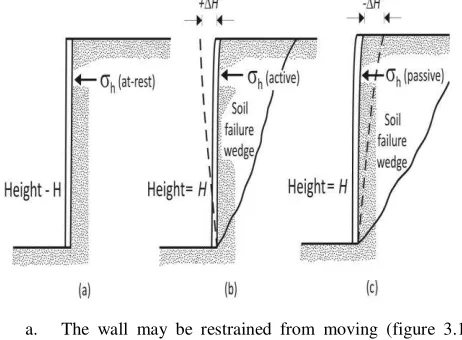
Vertical or near vertical slopes of soil are supported by retaining walls, cantilever sheet pile walls, sheet-pile bulkheads, braced cuts, and other similar structures same as abutment. The proper design of those structures required estimation of lateral earth pressure, which is a function of several factors, such as (a) type and amount of wall movement, (b) shear strength parameters of the soil, (c) unit weight of the soil, and (d) drainage conditions in the backfill. Figure 3.1 shows a retaining wall of height H. for similar types of backfill.
a. The wall may be restrained from moving (figure 3.1a). The lateral earth pressure on the wall at any depth is called the at-rest earth pressure.
b. The wall may tilt away from the soil retained (figure 3.1b). With sufficient wall tile, a triangular soil wedge behind the wall will fail. The lateral pressure for this condition is referred to as active earth pressure. c. c. The wall may be pushed into the soil retained (figure
3.1c). With sufficient wall movement, a soil wedge will fail. The lateral pressure for this condition is referred to as passive earth pressure.
The lateral earth pressure conditions described in section 2 involve walls that do not yield at all. However, if a wall tends to move away
from the soil a distance ∆�, as shown in figure 3.7a, the soil pressure on the wall at any depth will decrease. For a wall that is frictionless, the horizontal stress, �ℎ, at depth z will equal (� �z) when ∆� is
zero. However, with ∆�>0, �ℎ will be less than � ��.
Stability of Abutment
To check the stability of an abutment, the following steps are necessary:
1. Check for overturning about its toe 2. Check for sliding along its base
3. Check for bearing capacity failure of the base 4. Check for settlement
5. Check for overall stability
This section describes the procedure for checking for overturning and sliding and bearing capacity failure. Some problems regarding the overall stability of abutment are discussed in section.
Check for Overturning
Figure 3. 11 shows the forces acting on a cantilever and a gravity of abutment, based on the assumption that the Rankine active pressure is acting along a vertical plane �B drawn through the heel. is the Rankine passive pressure; recall that its magnitude is
Where
Σ � =sum of the moments of forces tending to overturn about point �
Σ ��=sum of the moments of forces tending to resist overturning about point �
The overturning moment is
Check for Sliding Along the Base
Where
Σ ��=sum of the horizontal resisting forces
Σ � =sum of the horizontal driving forces
Structure Design reinforcement of Abutment Reinforcement plate in one way
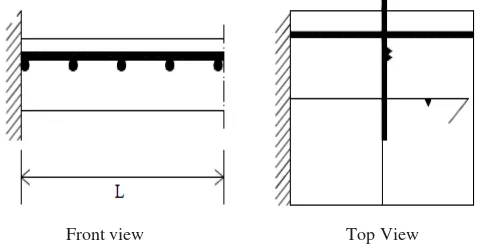
The one way reinforcement plate will be found if the plate cement more dominant in weight which is like bearing bending one direction. For. Because the bending moment only works in one way, namely the direction of L span, so then main reinforcement is also installed a one-way direction of that L span. To keep the position of main reinforcement (in the casting process) not changes in its position, so it will be installed additional reinforcement which is the direction same with the perpendicular direction to the main reinforcement. This reinforcement is commonly called fraction reinforcement.
Front view Top View Figure III.15. Cantilever with reinforcement plates principal one
direction (Asroni, 2010)
On the two pedestal parallel plate, the regional work field of positive moments, so that the main reinforcement installed under the bottom plate. When the pedestal area with negative moments, so that the main reinforcement installed above the plate. Either positive moment area or negative moments should be installed the main reinforcement and fraction reinforcement.
The calculation of reinforcement abutment
As have been explained above that the calculation of abutment based on gravitation calculation. After the stability calculation toward
the shifting and overthrowing is taken,
next step is looking for nominal moment and force
which happened in retaining wall, after that, it can be
started reinforcement calculation in retaining wall. The
reinforcement of retaining wall can be differed in:
a) The calculation of retaining wall reinforcement.
In this calculation the cantilever plate with assuming that the end plate is pinned. The calculation can be calculated with the formula:
Where
:
b)
The calculation of
retaining wall foundation.
There are two kinds of retaining wall foundation,
the first reinforcement in the end of front and back
foundation. Based on the calculation formula, it assumed that
the foundation with oblong. The used formula:
Introduction of Geo 5 v13 program
1.
Recognizing Geo 5 v13Geo 5 is one of the geotechnical application program which is fast used to assist in solving the problem in geotechnic. Geo 5 can assist in calculating – the calculation of stability to guling, stability against the sliding, overburden pressure, turn on Uplift, as well as analysis the wall dimension to suppor the soil. From the application program of getehnic.
2. The formula used in the program Geo5.
The formula used in calculating lateral earth pressure is slightly different from the lateral earth pressure formula which has been frequently used by the writer. The difference occurs because the reference to the standard calculation on each country. However, there are also standard calculations are often used in Indonesia, but the standard has been modified. The formula can be seen as follows:
a) Active earth Pressure by The Mazindarani Theory
(as rarely found in the book litelatur there). The formula can be seen
analyzed the soil’s condition and to design of an abutment using the
program Geo 5.
Research Data
The research is needed the data of soil in the Rehabilitation
Bridge of Pagotan Project in Pecitan such as soil density (γ), specific gravity (Gs), cohesion (c), and the friction angle (Φ). The
data can be shown
This program is a computer program used for calculation, stability controlling, visualization and that program make easy for the designer to simply enter the existing soil data and dimensions of retaining wall is desired, then the program will automatically analyzing and shown into a programming language that is easy to understand.
AutoCAD 2015
This program is a computer program used for draw of the structure details are required in design and structure calculations.
Microsoft Office 2013
This program is a computer program that is used to create reports, charts, flowcharts, analysis data and table creation
.
Research
Steps
Step I: A Literature Review.Step II: Data collection soil of the Rehabilitation Bridge of Pagotan Project in Pecitan.
Step III: From all the data that has been collected, design and analyzed of abutment made up of two ways, namely:
a. Calculation of abutment by using manual /Conventional. b. Calculation by using auxiliary programs (software) GEO5 v-13. Step IV: Discussion
Step V: Conclusions and suggestions Step VI: Finish
Implementation
of Research
Preparation for Data taking
In this design the case which is taken from the project of the Rehabilitation Bridge of Pagotan Project in Pecitan is designing an abutment which has existed namely with the abutment, therefore the data of soil needed has already been provided.
Analysis of Abutment with Manual Calculation by using Program GE05.
The data needed to analyze the abutment by using manual calculation namely the data in the project of the Rehabilitation Bridge of Pagotan Project in Pecitan such as the soil
density (ɤsoil), Coherent (c), and the shear angle inside (Φ), the
weight of concrete volume (ɤ concrete) also the height of congeries
or the height of slope which will be designed to be the abutment. From all of the data it is taken an analysis how much the lateral soil pressure, from the pressure of lateral soil it is derived the passive and active soil pressure. So from all parameters which has already been realized it can be planned the dimension of the abutment and analyzed the stability for the sliding and rolling.
ANALYSIS AND DISCUSSION
The design is based on the problem formula, where the
data of soil such as unit weight of soil (γsoil), cohesion (c), and
friction angle of soil (φ). The data is based on the test result in one
place (in situ test) or based on test result of laboratory which get from the field. After getting the parameter of planning abutment, the calculation of overturning and sliding stability can be done by manually and automatically with Geo5 program.
A. Getting the soil data
The calculation of abutment stability and dimension depend of the data can be seen below:
a.
Depth : 5.8 mb.
Density : 18 KN/m3c.
cohesion ( c ) : 0.00d.
Friction angle of oil ( φ ) : 30.00ºe.
Active soil pressure coefficient of Rankie (Ka) : 0.33 Data of concrete:a. Weight of concrete =2300kg/cm3 =23 KN/m3
b. specified compression strength of concrete(f’c) =20 Mpa
c. specified yield strength of nonprestressed reinforcing (fy)
=500 Mpa
B. Analysis of Abutment by Manual Calculation 1. The determining of early dimension of abutment
Picture V.1. Abutment applying forces diagram.
The calculation of lateral earth pressure Active force before the occurrence of tensile crack
The line of action the resultant can be determined by taking the moment of the area of the pressure diagrams about the bottom of the abutment.
The overturning moment can be given as
The safety factor of against overturning in point C
Check for sliding along the base The factor of safety against sliding
the sliding may be expressed by the equation
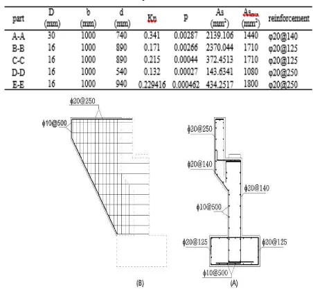
Calculation reinforcement of Abutment.
Figure 7. Stair Detail Section A-A
Element of structure
Secure planning dimensions is used as the structure of the building for secondary beam W14x38, Non-SMF beam W21x68, SMF beam W21x132, Non-SMF column W14x257, SMF column W14x370.
Connection
Connection between secondary beam to Non-SMF beam:
Figure V.6. (A) Abutment typical section design. (B) Wing wall reinforcing.
Discussion
From the calculation result above, it can be seen the manual stability calculation result and Geo5 program, as follow;
Table V.5. The stability calculation result of manual method and Geo 5 program
Stabilities manual Geo 5 Program
Safety
factor Remark
Overturning 3.07 4.01 2 Safety
Sliding 3.04 2.11 1.5 Safety
After observing the data result above, it can be known that the final result of manual calculation and Geo5 program get same safety factor for abutment stability but difference value between manual calculation and Geo5 program.
The difference is happened because the manual calculation, the lateral earth pressure is used Rankie method while in geo5 program, the earth pressure calculation using Rankie method which has been modified with Mazidrani. In calculating the earth pressure cohesive with active or passive, it directly enters the value of cohesive land, with formula:
While for Rankie method in calculating the cohesive active or passive earth pressure just by entering the angle friction inside and the soil obliqueness, with the formula:
CONCLUSION AND SUGGESTION Conclusion
From the analyzing result in chapter V, it can be concluded about abutment analysis of Pagotan bridge rehabilitation, Pacitan Java.
The structure abutment planning is safety from the moving, overthrowing from the capacity of soil support. The analysis result can be seen;
The manual calculation
a) Stability factor toward sliding 3.04> 1.5 (safety) b) Stability toward overthrowing 3.07 > 2 (safety)
The calculation result of Geo5 program
a) Stability toward overthrowing 4.01>2 (safety) b) Stability toward sliding 2.11>2 (safety)
The material structure of abutment used reinforcement:
The difference of stability calculation result between manual calculation and Geo5 program due to the formula or method which is used difference. In manual calculation, the writer uses Rankie method while in Geo5 program, the writer use Rankie method modification with Mazindrani theory.
Suggestion
2) For the beginning user of Geo5 program, they should understand all functions in the toolbar to avoid mistakes in entering the data.
3) In abutment designing, the designer should know the location which will be built. So that the planning of abutment can be calculated appropriately in that location. 4) When planning the abutment, the data should be complete
and accurate. To get the precision result.
REFFERENCE
Anonym, 2013, Abutment design theory, Accessed 23 March 2015. http://enggprog.com/
Anonym, 2015, Bridge Design & Assessment, Accessed 20 March 2015.http://www.childsceng.demon.co.uk/tutorial/ab utex.html
H. BROWN RUSSELL, JACK C. McCORMAC, (2009), Design reinforced of concrete. Clemson University.
Kisworo Gutama Rymo (2014), Perencanaan Dinding Gravitasi Dengan Program Geo 5. Universitas
Muhammadiyah Surakarta
NPTEL, LATERAL EARTH PRESSURE NPTEL- ADVANCED FOUNDATION ENGINEERING-
http://nptel.ac.in/courses/105105039/
NPTEL, RETAINING WALLS NPTEL- ADVANCED FOUNDATION ENGINEERING-1.
http://nptel.ac.in/courses/105105039/
Wang, L., Gong, C, (2009), "Abutments and Retaining Structures." Bridge Engineering Handbook.
Wikipedia, 2014, Definition of Abutment, Accessed 15 February 2015. http://en.wikipedia.org/wiki/Abutment Wikipedia, 2014, Definition of Bridge, Accessed 16 February
2015. http://en.wikipedia.org/wiki/Bridge Wikipedia, 2013, Lateral earth pressure, Accessed 2 March
2015. http://en.wi