1. BERNINI IN CASTEL GANDOLFO
This document illustrates a study focusing on the use of models for the survey, analysis and representation of architecture. The study was carried out by the Department of Planning and Archi-tectural Studies at Roma Tre University in collaboration with the Vatican Heritage Superintendence.
The study in question regards the Church of St. Thomas of Vil-lanova in Castel Gandolfo. Built between 1658 and 1662, the church was commissioned by Pope Alexander VII Chigi and de-signed by Gian Lorenzo Bernini.
THE USE OF 3D MODELS IN INTEGRATED SURVEY: THE CHURCH OF
ST. THOMAS OF VILLANOVA IN CASTEL GANDOLFO
M. Canciania, M. Sacconeb
a Roma Tre University, Department of Planning and Architectural Studies, [email protected], b [email protected]
KEY WORDS: San Tommaso da Villanova in Castel Gandolfo, G.L. Bernini, Integrated survey, Measurement model, Design model, Representation model
ABSTRACT:
The research illustrated below describes the integrated survey method as applied to the Church of St. Thomas of Villanova in Castel Gandolfo, the work of G. L. Bernini. In particular, integration of the various survey methods with 3D modelling to reconstruct all the elements with complex and/or hard to measure geometries has made it possible to obtain an accurate survey model. Comparison of this model with Bernini’s original project, based on the analysis of several drawings, has given a clearer view of certain aspects of the design and of Bernini’s planning methods.
It is located on the east side of the square in Castel Gandolfo at the top of a hill that runs from the square down to a lakeshore ter-race. The church has two superimposed parts: the upper church accessed through the main entrance in the square and dedicated to St. Thomas of Villanova, archbishop of Valencia, and the low-er, lakeside church consecrated to St. Nicholas to whom the old oratory was dedicated.
The layout of the upper church is based on a Greek cross, with a tholobate carrying a dome with an acute angled outer proile; the main facade, the central body of which stands out into the square, has two superimposed orders of columns, top and bottom, with a proportion of two to one.
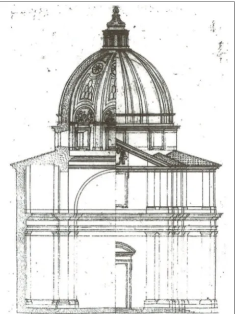
Figure 1. Photo of St. Thomas of Villanova in Castel Gandolfo Figure 2. Bernini’s design: Front view and cross section, 1658-1660, Biblioteca Vaticana, Chigi P VII 12 f. 11
2. THE DESIGN AND SURVEY DRAWINGS
Except for Bernini’s original design and survey drawings, very little else has been produced about the church in recent years. Bernini’s designs for the church illustrate the changes he made to the original idea while construction was ongoing; drawn between 1658 and 1660, they are now housed in the Vatican Library. A irst series of drawings (the initial draft layout, the front view overlooking the square and a side view, the plan drawing) *, re-fers to a version of the design with a tiburio and with the church isolated from the general context of the square, two orders of columns of the same size on the facade, the tiburio surrounding the drum in the central area; a second series of drawings (the cross-section, the main proile, drawings for construction of the cupola, the clerestory and the bell tower, studies for the lower church)**, relate to a solution with an acute angled cupola, dif-ferently proportioned orders of columns in the facade, connec-tion of the lower and upper church and addiconnec-tion of the sacristy. The survey documents and drawings by A. and G. Pierangeli were published in 2005 (Apa, Pierangeli, 2005); they include two loor plans, the elevations and transversal section of the church. Although the 1:100 scale drawings make it possible to assess the architecture designed by Bernini, it doesn’t help to appreciate all the architectural details and sophisticated solutions he envisaged. Furthermore, some drawings are inconsistent with the actual ar-chitecture of the church, while others are oversimpliied graphic representations.
As a result, the Vatican Heritage Superintendence commissioned a new 1:50 scale survey in order to obtain an extremely detailed graphic restitution of the church. The aim of the survey was to help in the study and enhancement of Bernini’s original design and act as the basis for a detailed architectural restoration project.
3. MEASUREMENT MODEL, SURVEY MODEL, DE-SIGN MODEL, REPRESENTATION MODEL
To carry out an accurate and exact survey (for example in the case of the Church of St. Thomas) and produce illustrations showing the importance of detail in the overall design, we devel-oped a combined method that included different kinds of direct survey procedures – traditional, topographic, photogrammetric. This was achieved by developing four georeferenced models; the measurement model, the survey model, the design model and the representation model.
The measurement model is a mix of more than one direct and indirect survey model coordinated in what is known as an “in-tegrated survey” system in which each survey method is used according to its speciic characteristics. Each model is closely linked to the others using a system of common points and geore-ferentiation in the same system of coordinates.
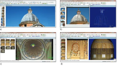
The survey model was used to reconstruct the drum, dome and lantern of the church and exploits “basic knowledge”, in other words, formal models illustrated in studies on the history of architecture, treatises and historical, archival and documentary Figure 3. Photomodeler screen shoot: a) topographic survey points marked on photo for photogrammetric restitution; b) restitution of the geometric model of cupola; c) theorical section model superimposed on photo; d) represented model of the intrados of the cupola
* Biblioteca Vaticana, Chigi PVII 12 f. 10, PVII 12 f. 12, Chigi a I 19 f. 10
** Biblioteca Vaticana, Chigi PVII 12 f. 11, Chigi PVII 12 f. 13 v., Chigi PVII 12 f. 13
a) b)
d) c)
studies.
The design model was reconstructed analysing Bernini’s original drawings.
The representation model collates and summarises the data pro-vided by the measurement and theoretical models; it selects the appropriate 3D data as well as the 2D images of plans, elevations and sections so that the drawings are correctly represented.
3.1 The measurement model
The measurement model has been created applying the “Inte-grated Survey” method. This method uses various systems: of an instrumental, topographic, photogrammetric and traditional direct type, which are integrated thanks to a common georefer-encing system.
The topographic survey, which uses a total station, generates a reference polygon with the topographic measurement stations at
Figure 7. The design model of the cupola Figure 5. The survey model of the cupola
Figure 6. Groin costruction model of cupola. In evidence the isocurves that set the surface
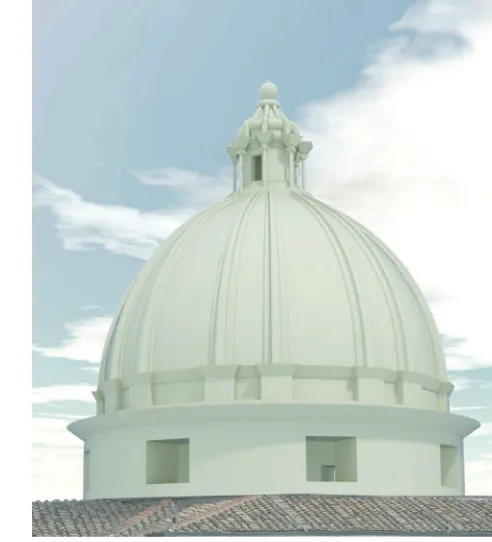
Figure 4. Photo of St. Thomas cupola
prospetto principale a - a'
rapp. 1:50 - 11/10/2010
04
its vertexes, and this forms the basis for georeferencing of all the survey models obtained using the various methods. A survey of the object is then carried out, while at the same time the pre-paratory drawings are prepared and then a manual survey of all the details (moldings, decorations, etc. etc.). All the preparatory drawings are inserted in the general reference system (as they contain the “known points”) and carry information on dimen-sions for control and veriication purposes. The next phase is the photogrammetric survey. Using a reproduction software, it is possible to use the photographs to reconstruct a photogrammetric model in which pairs of photos taken using the orientation in the general reference system (by importing the “known points”) make it possible to measure all the objects that are not detected using the other methods. The result of this process is a topo-graphic and a photogrammetric model that form the basis upon which to create the design model.
3.2 The survey model
Right from the early stages of work a double problem was en-countered. On the one hand there was a problem performing a proper survey on the roof and cupola of the church due to access or visibility questions, and on the other hand there was a problem representing the curvature of the cupola and groins properly. For this reason it was decided to create a complete three-dimensional model of the drum, the cupola and the entire decorative system in the clerestory. The model, which is constantly veriied using the few points that can be surveyed, has been divided into four main
parts: the drum, the cupola, the groins and the clerestory. The cu-pola has been constructed as surface of revolution, which by dei -nition requires an axis of rotation and a generatrix curve. The axis has been identiied starting from the horizontal section (plan) of the church, using the topographic survey model. Various circum-ferences have been built (on three points) passing through the centre of the four pilasters that support the drum, obtaining in this way a projection of the axis itself. Construction of the generatrix required use of the photogrammetric survey. Thanks to this in-strument it was possible to draw all the elements with great preci-sion, in particular the joints in the lead sheets that cover the outer surface of the cupola ad even the nails in the sheets themselves. In particular the drawing of the nails, which are almost perfectly aligned, allowed deinition of the outer proile both of the cupola and of the groins. The drum has been modelled as a surface of revolution using a procedure similar to the one described for the cupola, with the difference that the generatrix was detected us-ing the direct method thanks to the ability to access a walkway around the perimeter. The clerestory and groins, which cannot be accessed and are dificult to measure using the topographic instrument, were measured and recreated from the photogram-metric model. Construction of the groins in particular involved a special study relating to their geometry. The curvature of the out-er proile is diffout-erent from that of the innout-er proile, which rests on the crown of the cupola. Furthermore, the initial section and the inal section of the groin are different not only in size and propor -tions, but also in geometry. As a result it was necessary to build a bicubic surface interpolated between four edge curves (Coons surface), dividing the groin in half as illustrated in ig. XX. The clerestory and its decorative system has been modelled as a surface of revolution whose axis coincides with that of the cupo-la. The generatrix in this case derives from the topographic sur-vey model and from the preparatory drawings made on site. The composite columns that support the groins rest against the central body of the clerestory. The position and dimensions of the nails on the lead sheets on the cupola have also been obtained from
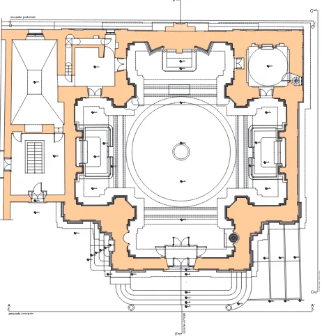
Figure 8. Represented model: Front view with in situ section Figure 9. Represented model: plan view
the photogrammetric model and inserted in the design model to complete the work.
3.3 The design model
The design model derives from knowledge of the church’s archi-tecture as it was planned and designed by Gian Lorenzo Bernini. Starting from drawings from the period, which were digitalised and entered into the general reference system, a three dimension-al model of the drum, the cupola with groins and the clerestory has been created. When constructing the cupola as a surface of revolution, the same axis used in the topographic survey model was used, while the generatrix was drawn (obtained or derived) from Bernini’s section. Again in this case, construction of the groins was carried out using a Coons surface. The curvature of the outer proile is the one from Bernini’s section, while that of the inner proile rests on the crown of the cupola. The sections, on the other hand, are similar to those in the survey model.
3.4 The representation model
As stated above, one of the main problems in representing the views of the Church of St. Thomas was drawing the curves of the groins. To solve this problem, 3D rendering of the orthogonal views was carried out. From the images obtained it was possible to draw all the elements in their correct forms and positions, par-ticularly as regards the elements directly in view, such as groins, nails, etc. etc. The model shown summarises the information from the measurement and survey models, carrying out a selec-tion of the 3D informaselec-tion in order to give a correct two-dimen-sional representation in the form of plans, views and sections. A plan view at a height of 2.60 mt, a longitudinal section and the three visible views (the fourth abouts onto another building) of
the Church of St. Thomas were prepared. The drawings were all in a scale of 1:50, showing indications of dimensions, heights and “in situ” sections. The decision to provide “in situ” sections indicates a desire to highlight the third dimension even in the two-dimensional views.
Figure 10. Comparison of front view: survey drawing (left) -
Bernini’s design drawing (right) Figure 11. Comparison of section: Bernini’s design drawing (left) - survey drawing (right)
Figure 12. Comparison plan model (left) - survey model (right)
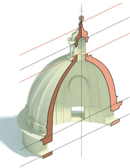
4. SUPERIMPOSING SURVEY / DESIGN
Superimposing the survey drawings and the plan drawings highlighted an extraordinary correspondence between Bernini’s original design intentions and the actual structure of the church, together with a high level of congruence and precision in the plan drawings. Analysis was carried out in particular on drawing located in Biblioteca Vaticana (Chigi P VII 12 f. 11), using the right hand portion, which shows a half-view of the main facade, abutting onto the left hand portion of the survey view and the left hand portion, relating to the cross section of the church, abutting onto the right hand section, relating to the survey.
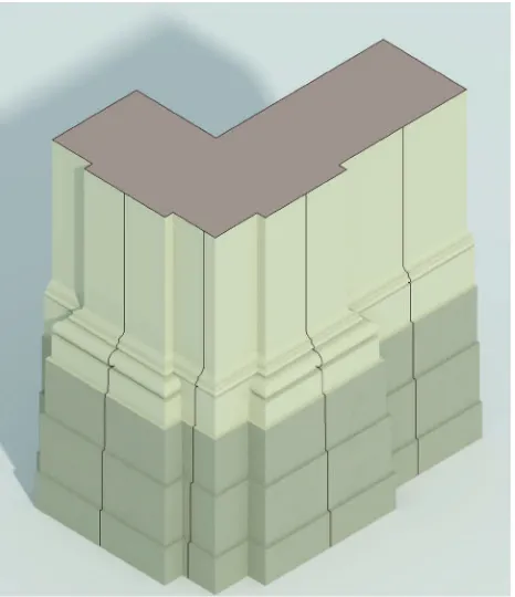
As regards comparison of the views, there is a substantial cor-respondence of positions, both as regards the height measure-ments, those of the main facade and the drum, the eaves, the cu-pola springer, the clerestory, and as regards the dimensions and proportions of the elements in the architectural order, the base plinth, the main door, the entablature frieze; also not the correct and strict representation of the roof covering layers, orientation of the windows in the drum, the design of the cupola groins; drawing of the corner solution of the architectural order, which is simpliied at the corner, rectifying the curved moldings. This solution is a detail that highlights the Bernini’s skill in solving the problem of turning back the order and demonstrates how this was done exactly as shown in the plan drawings.
When comparing the sections, as in the case of the view, the cor-respondence and congruence between plan and execution can be noted, up to the level of the drum (for example the windows and the cornice connecting with the cupola), whereas the section of
the cupola is slightly different. In Bernini’s plan the cupola was taller and thinner, with a more steeply inclined curve to the sec-tion, whereas in the actual construction the cupola is fatter, with the central aperture, on which the clerestory rests, is at a lower height and the clerestory itself is reduced in height. The inner proile of the cupola is also substantially different: in the one actually constructed there are a series of boxes encased within the pilaster strips, with the windows surmounted by cherubs and garlands and large ovals with igures in bas relief, whereas in the drawings the structure was lightened by a series of arches, placed over the windows.
When observing Bernini’s drawing, with the section next to the survey, another detail can also be seen, and is noted in particular in the survey section drawing, that is to say the church’s internal and external molding is more or less aligned horizontally, and in the plan drawing the internal and external part of the molding actually coincides.
The two sets of molding, which Bernini intended to stress the visual and spatial continuity between the exterior and the interior of the church, differ only in that the internal one is more curv-ing (some of the strips in the external moldcurv-ing are replaced by grooves in the internal molding), while the external one is more regular.
5. CONCLUSIONS
One aim of this study is to emphasise the importance of an in-tegrated survey method in the organisation and correct manage-ment of the data provided by each survey. Another is to fully exploit the potential afforded by the analysis and comparison of the different models. In fact, the study’s added value lies in the elaboration of a method allowing consultation of the survey model during the entire process and the superimposition of the Figure 13. Comparison of detail section of cupola and lanterna:
a) design model; b) survey model
Figure 14. Axonometric view of the Church angle solution with in situ sections
a) b)
measurement and theoretical model in order to underscore dif-ferences, deiciencies and anomalies between the original design, shown in its “ideal coniguration”, and the actual building, as shown by the detailed survey.
When comparing the survey models and the plans, not only the accuracy and precision with which the drawings were made can be seen, but also the strict method employed by Bernini when developing the plan, using compound drawings, combining the section with the prospect view, to underline the correspondences and alignments between interior and exterior and to establish the reference elevations.
6. REFERENCES
Apa M., Pierangeli A., 2005, Gian Lorenzo Bernini La Chiesa di
San Tommaso da Villanova a Castel Gandolfo, L’Aquila
Maestri D., Canciani M., Spadafora G., 2001. Archaeological
Survey: data processing experimentation and direct observation,
in The Cipa International Archives of Cultural Documentation, Volume XVIII, Berlin.
Maestri D., Docci M., 1999. Manuale di rilevamento
architet-tonico. Editori Laterza, Bari 1993, reprint 1999.
Maestri D., Canciani M., Spadafora G., 2007, The integrated sur-vey for the knowledge and the documentation of the
archaeologi-cal heritage: the “Villa dei Misteri in Pompei.”, in the archives
of XXI CIPA international simposium “Anticipating the future of the cultural past”, Atene.
Canciani M., 2007, Il sistema informativo geograico come stru -mento progettuale: il caso di studio del Masterplan della Medina
di Costantina”, in the archives of EARCOMM 2007 “Sistemi
informativi per l’architettura”, Ancona.
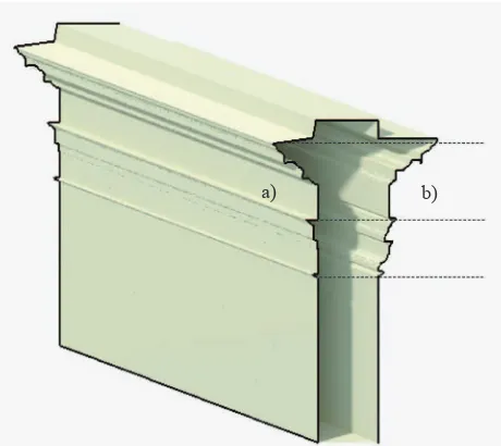
Figure 15. Detail of the mouldings at a) exterior end b) interior façade
a) b)